3
aLoctite No. 225. b Loctite No. 243. c Not for plastic paint nozzle. d Set of 10. eSold singly. f Set of 5. g
Including in service set.
Ref. Qty
No. Part number Description
Part numbers in bold type designate consumption parts.
Service set 6003 9095 00 for Ecco 65S, -651S, -652S
Consists of parts with ref. Nos. 2, 3 (Qty 1), 7, 10, 11, 19, 20, 22, 23,
25, 27, 29 and 31.
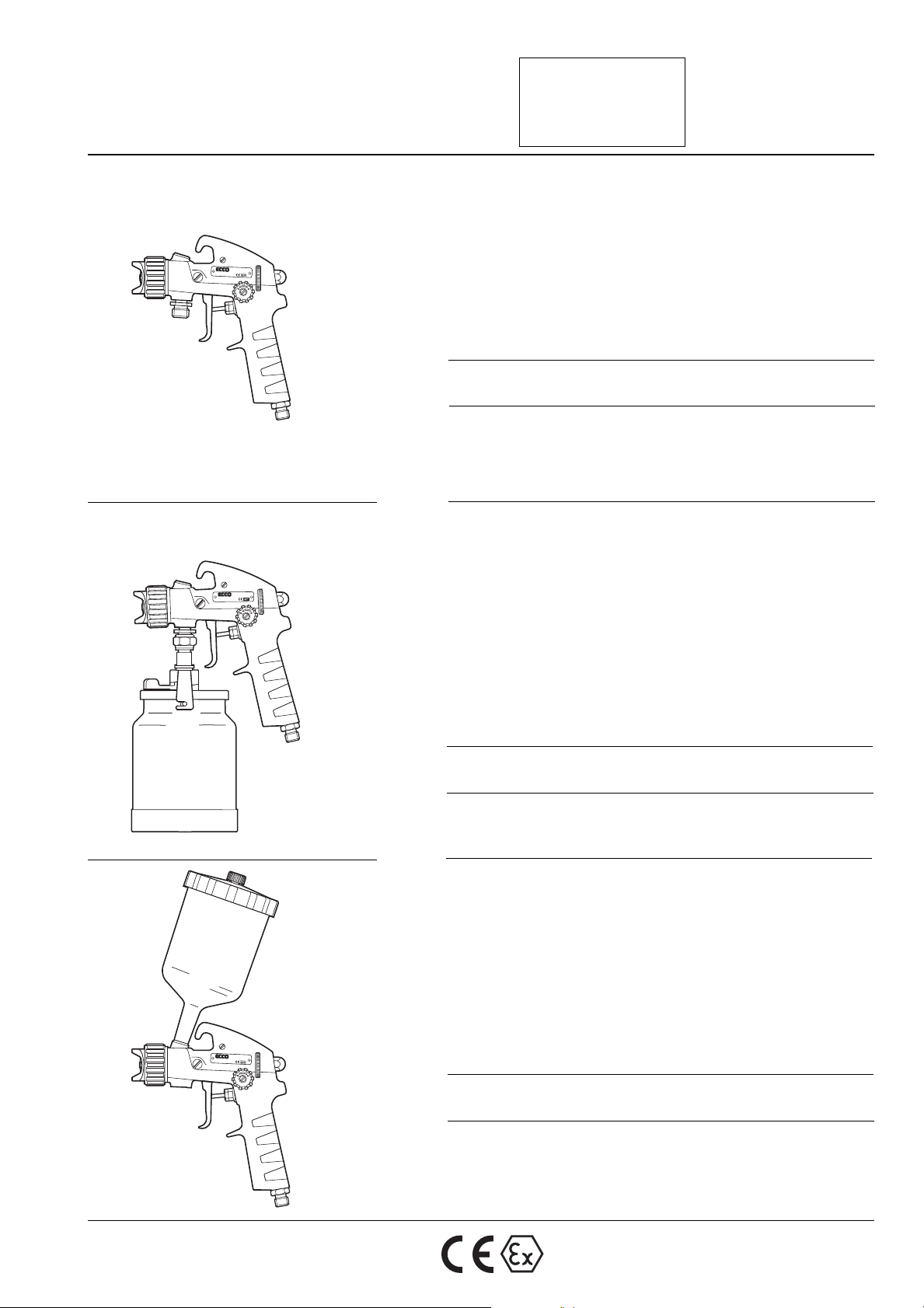
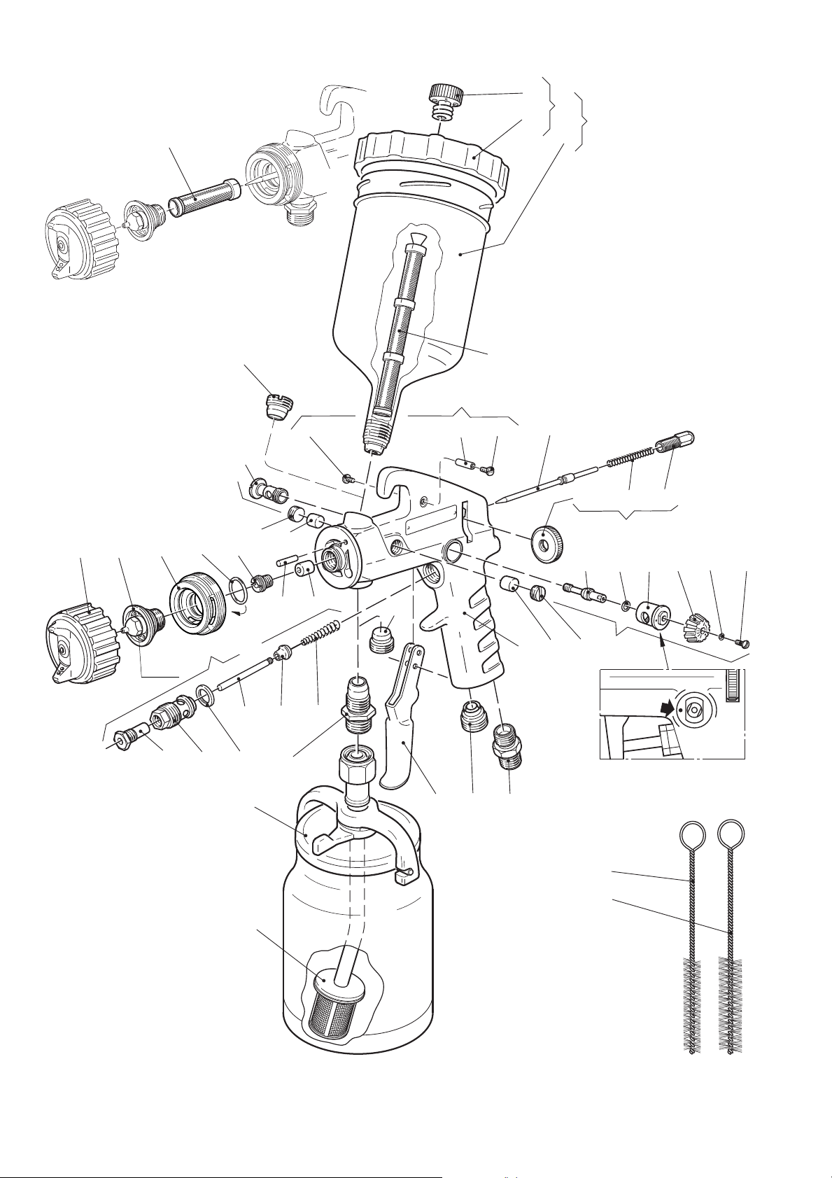
1 – 1 1 1 Gun body
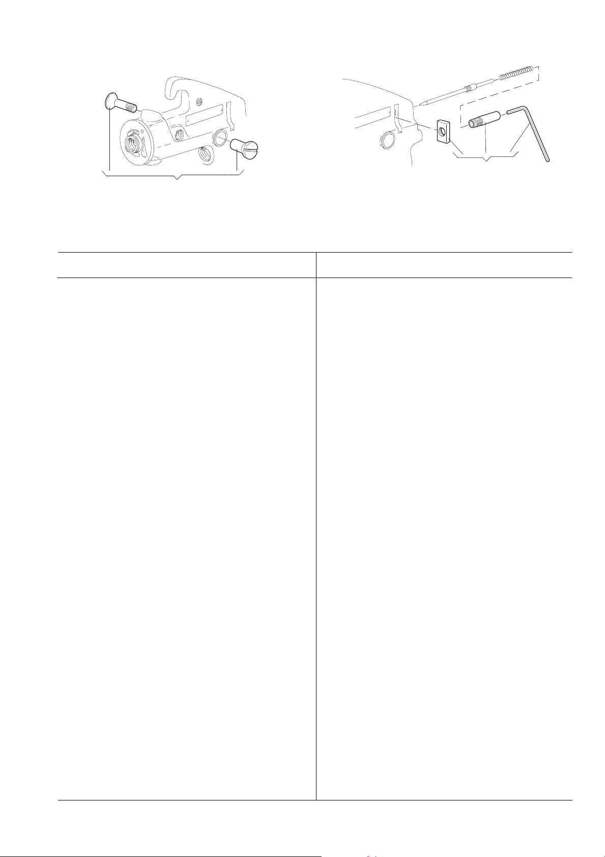
2 6102 2401 00g1 1 1 Packing set
3 6000 8369 00g2 2 2 Packing screw (stainless steel)
4 6101 5100 00 1 1 1 Fan width control, compl.
5 6101 3788 00 1 1 1 – Valve screw
6 6101 3790 00 1 1 1 – Valve pin
7 6101 3796 00g1 1 1 – O-ring
8 6101 3789 00 1 1 1 – Valve housing
9 6101 3648 00 1 1 1 – Wheel
10 0333 5109 00g1 1 1 – Lock washer (V 3.2)
11 0164 5013 00g1 1 1 – Screw (MKFS 3 x 6 SS A2)
12 (see page 4) 1 1 1 Paint needle
13 6000 9191 80 1 1 1 Back head, compl.
14 6000 9191 00 1 1 1 – Back head
15 6101 2582 00 1 1 1 – Spring (3.4 kg)
16 6000 7764 00 1 1 1 – Wheel
17 6101 2796 00 1 1 1 Trigger (stainless steel)
18 6101 2990 80 1 1 1 Shaft, coml.
19 6101 2990 00g1 1 1 – Shaft (stainless steel)
20 0164 5013 91g2 2 2 – Screw (MSCS A4-70 3 x 6
stainless steel)
21 6101 5730 00 1 1 1 Air valve, compl.
22 6101 2111 00g1 1 1 – Spring
23 6101 5008 00g1 1 1 – Air valve
24 6101 3631 00 1 1 1 – Valve pin
25 6001 1008 00g1 1 1 – Packlng
26 6003 2167 00 1 1 1 – Valve housing
27 6101 5716 00g1 1 1 – Bushing
28 0101 4131 00b1 1 1 Pin (CP 4h6 x 10 S )
29 6103 3112 00g1 1 1 Screw (stainless steel)
30 6102 1214 00 1 1 1 Distribution ring with O-ring
31 6101 1724 00g1 1 1 – O-ring
32 (see page 4) 1 1 1 Paint nozzle
33 (see page 4) 1 1 1 Air cap
34 6001 2619 00a1 1 1 Nipple (G 1/4)
35 6101 5560 00 – – 1 Paint cup Ecco G 5, compl.
36 6101 5561 00 – – 1 – Paint cup (G 3/8) volume 0.5 l
37 6101 5559 00 – – 1 – Cover, compl.
38 6003 9094 00 – – 1 – – Cover
39 6003 9068 00 – – 1 – – Plug (Drip guard)
40 6003 9974 00 1 1 – Plug (G 3/8)
41 6101 3742 00 – – 1 Plug (M14 x1)
42 6101 5021 00 1 1 – Nipple (G 3/8 stainless steel)
43 6101 5626 00 1 1 1 Plug (G 3/8 )
44 6003 9714 00 – 1 – Suction cup Ecco SD 15,
volume 1 l (see spare parts list
No. 9836 3175, ESL 12/04-20)
45 6000 8004 00 1 1 1 Cleaning brush (ø10 mm)
46 6000 8001 00 1 1 1 Cleaning brush (ø17 mm)
47 (see optional 3 3 – Strainer 100 mesh
equipment)
48 (see optional – – 1 Strainer 100 mesh (yellow)
equipment)
Optional Equipment
-65S -651S -652S -65S -651S -652S
Ref. Qty
No. Part number Description
– 6101 6065 00 1 1 1 Retaining ring, acetal plastic
(for air cap)
4 6101 9230 00 1 1 1 Fan width control for left
handed
4 6003 9602 00 1 1 1 Quick fan width control
15 6101 2582 65 1 1 1 Spring, soft (2.7 kg)
15 6001 2036 00 1 – – Spring, stiff (6.4 kg)
30 6102 1215 00 1 1 1 Distribution ring, compl.
(stainless steel threads)
34 6000 1877 00 1 1 1 Air inlet nipple (9/16" 20G)
34 6002 0233 00 1 1 1 Air inlet nipple (1/4" 18 NPSM)
35 6101 5560 95 – – 1 Paint cup Ecco G 1.25,
volume 0.125 l
42 6003 7393 00 1 – – Paint inlet nipple (9/16" 20G
stainless steel)
44 6003 9714 00 1 – – Suction cup Ecco SD 15,
volume 1 l
44 6003 9676 00 1 1 – Suction cup Ecco SD 15T,
volume 1 l (inside coated with
teflon)
44 6803 4867 00 1 1 – Suction cup Ecco SD 10,
volume 1 l
47 6103 3200 00c1 1 1 Strainer setd60 mesh (white)
47 6103 3201 00c1 1 1 Strainer setd 100 mesh (yellow)
47 6103 3202 00c1 1 1 Strainer setd200 mesh (black)
47 6103 1088 00c1 1 1 Strainere300 mesh (red)
48 6003 9754 05 – – 1 Strainer setf60 mesh (white)
48 6003 9752 05 – – 1 Strainer setf100 mesh (yellow)
49 6003 7886 00 – 1 – Strainer setd 80 mesh
50 6101 5247 80 1 1 1 Plug set, for gun is not fitted
with fan width control
51 6102 1203 80 1 1 1 Back head, lockable fluid
volyme control
– 6003 9249 00 1 1 1 Testing air pressure gauge
(incl. connection parts, excl.
testingaircap)
– 6003 9249 09 1 1 1 Testing air cap 6509
– 6003 9249 11 1 1 1 Testing air cap 6511
– 6003 9249 14 1 1 1 Testing air cap 6514
– 6003 9249 18 1 1 1 Testing air cap 6518
– 6003 9249 21 1 1 1 Testing air cap 6521
65130 F287 65130 F288
50
51