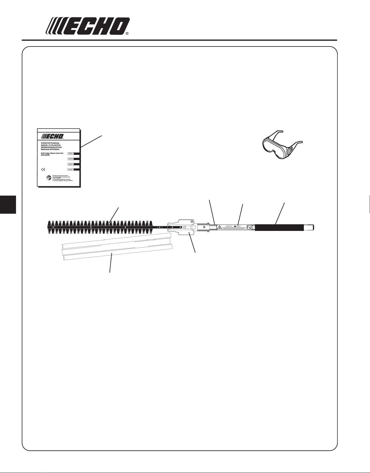
SHAFT HEDGE CLIPPER ATTACHMENT
OPERATOR'SMANUAL 7
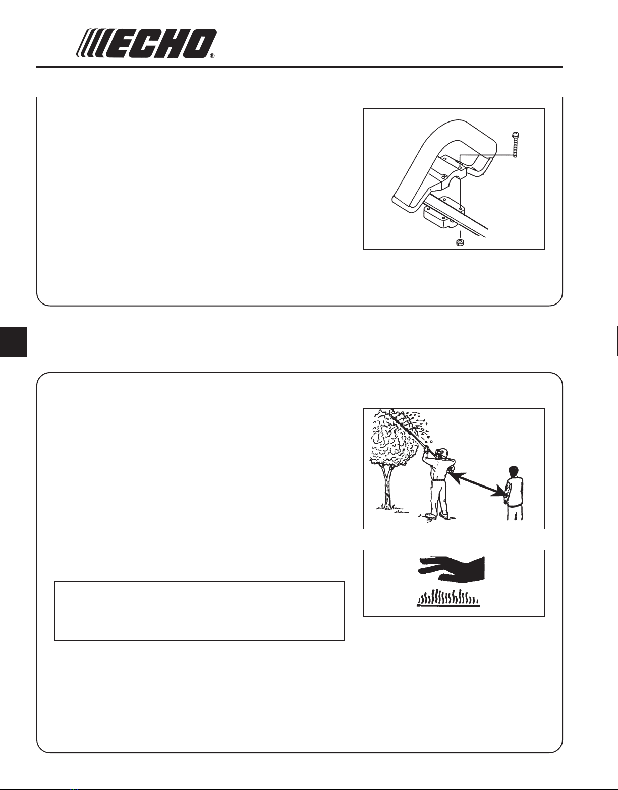
EXTENDED OPERATION/EXTREME CONDITIONS
Vibration and Cold --
It is believed that a condition called Raynaud’s Phenomenon, which
affects the fingers of certain individuals may be brought about by
exposure to vibration and cold. Exposure to vibration and cold may
cause tingling and burning sensations followed by loss of color and
numbness in the fingers. The following precautions are strongly
recommended because the minimum exposure which might trigger the
ailment is unknown.
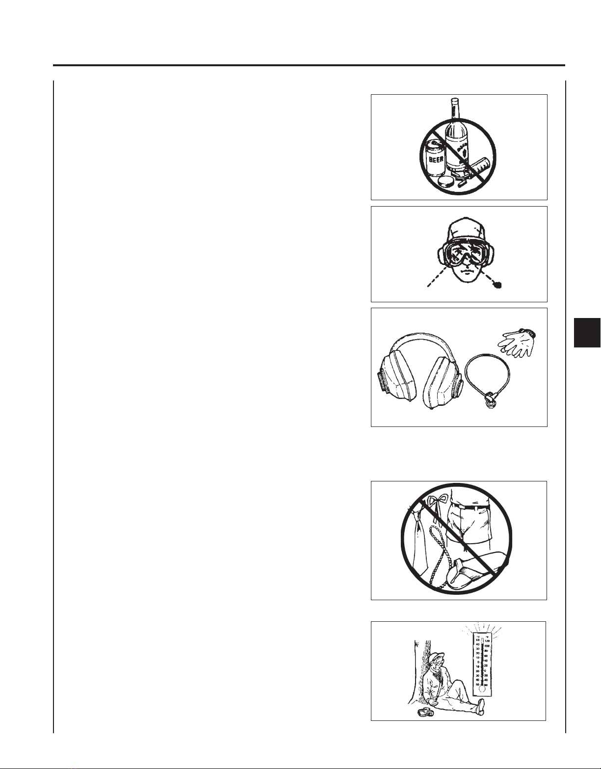
• Keep your body warm, especially the head, neck, feet, ankles, hands
and wrists.
• Maintain good blood circulation by performing vigorous arm
exercises during frequent work breaks and also by not smoking.
• Limit the hours of operation. Try to fill each day with jobs where
operating the unit or other hand-held power equipment is not
required.
• If you experience discomfort, redness and swelling of the fingers
followed by whitening and loss of feeling, consult your physician
before further exposing yourself to cold and vibration.
Repetitive Stress Injuries --
It is believed that overusing the muscles and tendons of the fingers,
hands, arms and shoulders may cause soreness, swelling, numbness,
weakness and extreme pain in those areas. Certain repetitive hand
activities may put you at a high risk for developing a Repetitive Stress
Injury (RSI). An extreme RSI condition is Carpal Tunnel Syndrome
(CTS), which could occur when your wrist swells and squeezes a vital
nerve that runs through the area. Some believe that prolonged exposure
to vibration may contribute to CTS. CTS can cause severe pain for
months or even years.
To reduce the risk of RSI/CTS, do the following:
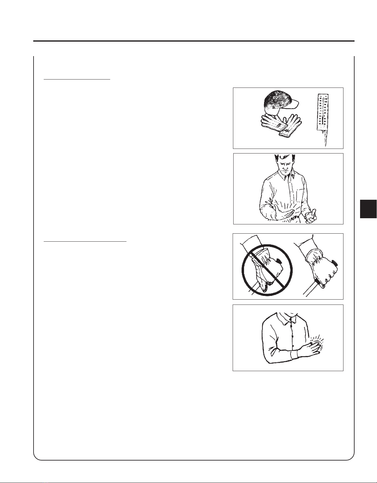
• Avoid using your wrist in a bent, extended or twisted position. Instead
try to maintain a straight wrist position. Also, when grasping, use
your whole hand, not just the thumb and index finger.
• Take periodic breaks to minimize repetition and rest your hands.
• Reduce the speed and force with which you do the repetitive
movement.
• Do exercises to strengthen the hand and arm muscles.
• Immediately stop using all power equipment and consult a doctor if
you feel tingling, numbness or pain in the fingers, hands, wrists or
arms. The sooner RSI/CTS is diagnosed,the more likely permanent
nerve and muscle damage can be prevented.