Echo shindaiwa SP41BPS User manual

013527-4 R0317
Carefully Read These Instructions Before Use
WARNING
Model SP41BPS
4G/ 15L
BackpackBackpack
SprayerSprayer
Use and Care ManualUse and Care Manual

WARNING
CAUTION
1E
WARNING: Improper use or failure to follow instructions can result in explosive
failure causing serious eye or other injury. For safe use of this product you must read
and follow all instructions. Do not leave a pressurized sprayer in the hot sun. Heat can cause
pressure build-up resulting in possible explosion. Do not store or leave solution in tank after
use. Always wear goggles, gloves, long sleeve shirt, long pants and full foot protection when
spraying. Never use any tool to remove pump if there is pressure in the pressure chamber.
Never pressurize sprayer by any means other than the original pump. Do not attempt to
modify this sprayer. Replace parts only with manufacturer’s original parts. Never spray
ammable, caustic, acidic, chlorine, bleach or other corrosive solutions or
heat, pressure, or gas producing chemicals. Always read and follow chemical
manufacturer’s instructions before use with this sprayer as some chemicals
may be hazardous when used with this sprayer.
SK 1158-1
• PRE-USE CHECK: Before each use check tightness of hose nut to be sure hose is
securelyattachedtotheshut-oassembly.Insurehoseissecurelyattachedtothe
tankbytighteninghoseclampifnecessary.Insurethatallnozzleandwand
connectionsaretight.Insurethelargepumpclampistight.Insurethe2bolts
used to attach the pump lever to the pump shaft are tight.
• DoNotexceedatanksolutiontemperatureof120ºF/49ºC.
NOTE: The tank and hose may have residual water in it due to quality testing
performed on the sprayer.
WARNING:
This product contains chemicals, including lead, known to the
state of California to cause birth defects and other reproductive harm. Wash
hands after handling.

1. Poly
Nozzle Cap
2. Retaining
Nut
3. Nozzle
Body
4. Nozzle
Gasket
5. Elbow
Figure 3Figure 2Figure 1
1. Brass
Nozzle Cap
2. Retaining
Nut
3. Nozzle
Body
4. Nozzle
Gasket
5. Elbow
Nozzle
Gasket
Retaining Nut
Elbow
Fan Nozzle Tip
2E
APPLICATIONS & USE FOR YOUR SPRAYER
Avoid using a sprayer for general cleaning purposes if plant protection or herbicide chemicals have
alreadybeenusedinthesprayer.Ifasprayerhasbeenusedforplantprotectionorasanherbicide,clean
the sprayer completely (see cleaning section) before using.
Plant Food:Usedierentspraypatternsforoptimumfoliagefeedingorforfungicideandpesticide
application.
Herbicides: Reduce weeds and unwanted plants but avoid using the same sprayer for plant feeding or
protectionwithoutthoroughlycleaning(seecleaningsection)thesprayerfirst.
General Household Use: Apply detergents, cleaning solutions, warm water (do not exceed
120°F/49°C)ornontoxichouseholdcleaningchemicalsforcarpets,floors,walls,glass,countertopsand
ceilings. DO NOT use sprayer that has been used with herbicides, pesticides or other toxic chemicals for
household applications.
General Outdoor Use: Use the sprayer for cleaning windows or with a detergent for general purpose
cleaning.
SPRAYER COMPONENTS & USE INFORMATION
NOZZLE ASSEMBLY
Figure 1-2
Unscrew the nozzle cap (1) from the nozzle body (3) with retaining nut (2) fastened tightly to the
elbow (5). Unscrew the retaining nut (2). Push the nozzle body (3) with the nozzle gasket (4) out of
the retaining nut (2). To reinstall the nozzle, reverse the above instructions.
Figure 3
Unscrew the retaining nut from the elbow and push the fan nozzle tip and gasket out of the retaining
nut. To reinstall the nozzle, reverse the above instructions.

3E
SPRAYER COMPONENTS & USE INFORMATION, Continued
WAND ASSEMBLY
1.Makesuretheo-ringisinstalledontheendofthewand.Insertthewandintoshut-ovalve.
2.Turnandtightentheretainingnutclock-wiseontotheshut-ovalve.
O-ring
Wand
Retaining Nut Shut-off
Valve
Pump Handle
Positioned For Use
(right hand shown)
Figure 1 Figure 2
Line up holes
Figure 3
Slide bolt through holes
Figure 5
Right Hand
INSTALLING THE PUMP HANDLE
The pump handle can be mounted on either side of the pump shaft
(A). To install the pump handle place the handle (C) over the shaft
(A) aligning the pump handle holes and shaft holes. Slide the bolts
(B)throughthealignedholesasshowninfigure1thru4.Tighten
nuts (D) to bolts. There are holes in the pump handle to allow for
eitherright(fig.5)orleft(fig.6)handmounting.
Figure 6
Left Hand
Figure 4
Tighten nut to bolt
Threaded Bolt
Nylon Lock Nut
C. Pump Handle
A. Pump Shaft
B. Bolts
D. Nuts

STOWAWAY PUMP HANDLE
Pull
up
Rotate
180º
Set
into
slot
WAND CLIP
The wand can be
attached to the
pump handle
using the wand
clip.
The backpack strap is provided with multiple features
including shoulder strap, chest strap, waist belt, lumbar
supportandbackpad(figure1).Thetopofboththeshoulder
straps and back pad straps are attached to the top of the tank
and are removable. The back pad strap attaches to the bottom
ofthetank(figure2).Thebackpadisattachedtoitsstrapwith
velcroandisremovable(figure3).Thestrapfromthelumbar
support attaches to the base tube on the bottom of the tank
(figure4).
Intheeventthatthesprayerharness(straps)become
contaminated with chemicals, it is recommended to
thoroughly wash the straps with soap & water and allow to dry
before using the sprayer.
INSTALLING THE SHOULDER STRAP
Figure 1
Strap Assembly
Shoulder
Strap
Back
Pad
Chest Strap
Lumbar
Support
Waist Belt
Figure 2
Back Pad strap attachment
Back Pad
Strap
Removable
Back Pad
Velcro
Attachment
Figure 3
Removable Back Pad
Lumbar
Support
Base Tube
Figure 4
Strap Attachment
4E

5E
Stage 3
(removable
Shut-off filter)
FILLING THE SPRAYER
Makesurethefilterbasketisinplacetokeepdebrisfromenteringthetank.
Determine the amount of mixture needed for your application. Add the proper amount of water to
the tank. Add the proper amount of chemical to the tank (check the chemical label for proper ratio of
chemical).Stirmixtureintankwithacleanutensil(likeapaintstirrer).Thetankwillholdthe4-gallon
(15.1L)capacityplusthechemical.
Itisnotnecessarytocompletelyfillthesprayertankwitheachuse.Youcanfillthetankwithonlythe
amount needed for each application.
Always follow the manufacturer’s instructions included on their product label.
Figure 2 Stage 2 (removable In-Tank filter)
Guide edge facing away from
pressure cylinder Guide edge on pressure
cylinder
Figure 1 Stage 1
(Filter
basket)
3 STAGE FILTERING SYSTEM
Stage 2
(Removable
In-Tank Filter
Pressure
Cylinder
Thisbackpacksprayerisequippedwitha3stagefilteringsystem(seefigure
1).Stage1isafilterbasketincorporatedintothetankopeningwherefluidis
added.Stage2filterislocatedattheinletofthepressurecylinder.Stage2
isaremovableIn-Tankfilter.Stage3isaremovablefilterincorporatedinto
theshut-oassembly.Periodiccleaningofthesefiltersisrecommendedto
insureconsistentfluidflowthroughthesprayer.Thiswillalsoreducesprayer
component wear.
Thestage3filterisaremovablefilterincorporatedintotheinletsideofthe
shut-ovalve(seesection“disassemblingandrepairingtheshut-ovalve”).
Makesurepressureisreleasedbeforedetachingthehosefromtheshut-o.
Itisbesttohavenoorminimalfluidinthepressurecylinderbeforeremoving
andreinstallingthestage3shut-ofilterasfluidcanleakfromthehose.
SPRAYER COMPONENTS & USE INFORMATION, Continued

6E
SPRAYER COMPONENTS & USE INFORMATION, Continued
HELPFUL SPRAYING INFORMATION
UseRAPIDpumpstrokestoprimethepump.Youwillknowthepressurechamberisfillingwithliquid
whenyoufeelfirmresistancefromthepump.Theairinthepressurechamberiscompressedfrom
repeatedstrokes.Bypressingthehandleverontheshut-o,thevalveopens.Forsafetylock-ofeature
(no-spraying),pulluponhandleandmoveredlockingmechanismintolock-opositionasshowninfig.
1.Todisengage,pulluponhandleandreturnredlockingmechanismtoneutralpositionasinfig.3.For
lock-on feature (continuous spraying), push down on handle and move red locking mechanism into lock-
onpositionasshowninfig.2.Todisengage,pushdownonhandleandreturnredlockingmechanismto
neutralpositionasshowninfig.3.
Intheeventthatthehandlebecomesstuckinthelock-on(continuousspraying)positionandthetank
pressure needs to be relieved, carefully open the tank and place the wand inside the tank until the pressure
is relieved.
LOCK-ON POSITION NEUTRAL POSITIONLOCK-OFF POSITION
Locking Mechanism Handle
Down
Handle
Up
Figure 1 Figure 2 Figure 3
For easy pump action use the END of the pump handle. The amount of liquid delivered during spraying
dependsontherateofpumpstroke.Thefannozzletipisratedat.4gpmat40psi.Thisisthenominal
operating pressure of the sprayer.
Note:Ifyouexperiencearapiddropinpressure,drainthesprayercompletelyandpumpthehandle
withanemptytank.Thepressurechamberwillfillwiththerequiredvolumeofairtorepressurize.
Perform this procedure from time to time as routine maintenance.
POWDER-BASED CHEMICALS
Powder-based chemicals (powder mixed with liquids to make the spraying agent) are usually abrasive
and can cause wear. When you use a powder-based chemical in your sprayer, make sure it is thoroughly
dissolvedintheliquidsolution.Thoroughlycleanandflushthesprayerwithwatertoextendthelifeof
the sprayers parts.
CLEANING
1) Always empty the sprayer and clean the tank thoroughly after each use.
2)Pumpthesprayerhandleuntilallofthecontentsandairexitthroughthenozzle(minimumof
30strokes).
3)Filltankhalfwaywithwaterandpumpthewateroutasexplainedinstep2(repeatseveraltimes
as necessary).
Other Cleaning Hints:
• Improperspraydistributionusuallymeansthenozzleisclogged,removethenozzleandcleanit.
• Soap can be added to the water to clean the tank.
• Do not use strong cleaning agents or abrasives.
• Ifyouuseachemicalagenttocleanthetankfollowthemanufacturer’srecommendationsforthe
disposal of the waste water.
• Follow the chemical manufacturers instructions for clean up.

Difficulty actuating the pump lever and/or Upper valve plate sticks Clean or replace valve plate
pump handle moves itself back up. Piston cylinder outlet passage clogged Clean piston cylinder outlet passage
Little or no resistance during Damaged/worn/dirty/upper and or lower valve plate Clean or Replace Valve Plate
repeated pumping – no pressure. Damaged /worn upper o-ring on piston Replace O-ring
Piston Collar or piston cylinder assembly is worn Replace Collar or Piston cylinder assembly
Too much resistance after just a few Not enough air cushion in the pressure Release pressure in pressure chamber
pumping strokes but pressure only lasts chamber Remove the hose & drain pressure
briefly. chamber. Reconnect the hose.
Upper valve plate damaged/worn/dirty Clean or replace upper valve plate
Upward pumping action is more difficult Vent hole is clogged Clear the vent hole in cap
and/or pump handle moves itself Lower valve plate sticks Clean or replace the valve plate
backdown. Clogged filter Clean in tank filter
Piston cylinder intake clogged Clean piston cylinder intake
When the handle is pulled up it moves Valve Plate sticking Clean or replace valve plate
itself back down
Leaks at Piston Cylinder Damaged/worn/Dirty Collar Clean or Replace Piston Collar
Damaged Piston Cylinder Replace Piston Cylinder
Damaged Piston Replace Piston
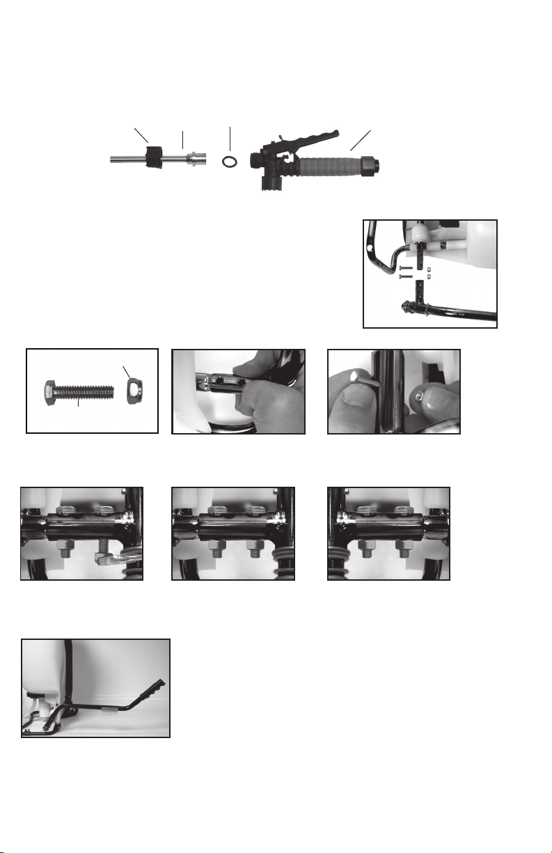
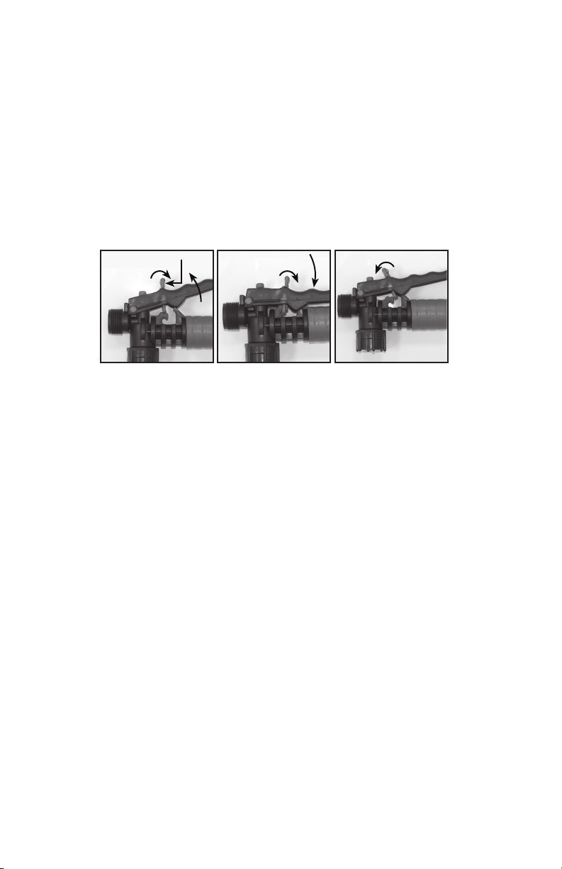
Shut-off leaks Connections loose Tighten connection
Worn or damaged shut-off Rebuild or replace the shut-off valve
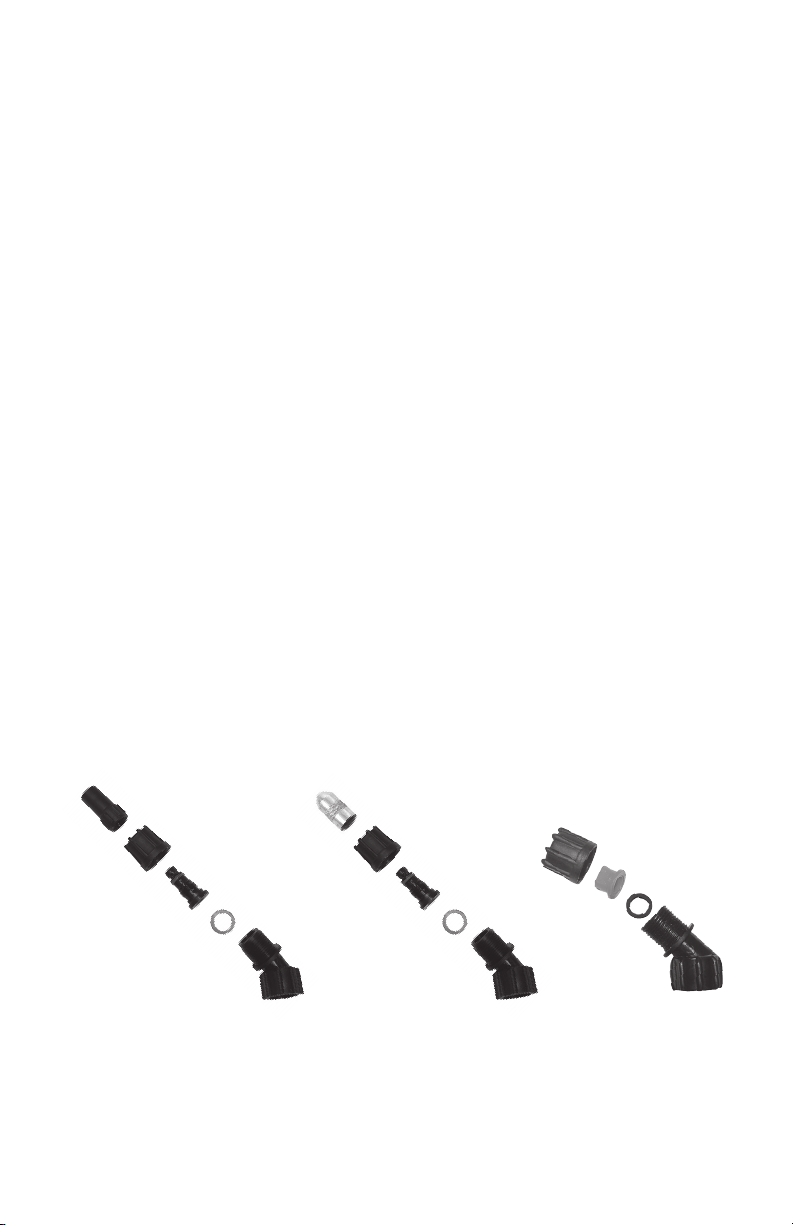
Wand assembly leaks Connections loose Tighten connection
Damaged or worn o-ring/gasket Replace o-ring/gasket
Nozzle assembly leaks Connections loose Tighten connection
Damaged or worn o-ring/gasket Replace o-ring/gasket
Leak between pump assembly Pump clamp loose Tighten clamp
and tank O-ring worn or damaged Replace pressure chamber o-ring
Hose leaking at tank outlet Hose clamp loose Tighten clamp
Hose leaking at shut-off Connection loose Tighten retaining nut
Damaged or worn o-ring/gasket Replace o-ring/gasket
STORING / MAINTAINING YOUR SPRAYER
• The sprayer should be stored out of direct sunlight in a cool dry space.
• Before freezing weather make sure to drain all liquid in the tank, pump, pressure cylinder, hose,
shut-ovalve,wandandnozzle,toavoidliquidexpansionandcrackinginthesprayercomponents
(See“Cleaning”section).Locktheshut-ovalveinthe“open”position.
• When service is required call your nearest dealer and always insist on original manufactured
replacement parts.
•Inspectthehose,wand,pump,tankandshut-ovalveforwear,damageorleaksonaregularbasis
and repair defects promptly.
TROUBLE SHOOTING YOUR SPRAYER
Symptom Possible Reason Correction
7E

8E
DISASSEMBLING AND REPAIRING THE PISTON PUMP
1) Remove the cotter pin and pump handle. With the pump facing towards you
laytheunitonitsback(Figure1).Loosenthehoseclampandremovethe
sprayer hose. Caution: There could be residual liquid in the hose and pressure
cylinder. Remove the nut and bolt from the protective cap and remove the cap
(ref:figure9).Rotatethepumpshaftinordertoreachtwoleverbolts(A).Using
an allen wrench, remove the lever bolts. Pull the piston assembly (B) out of the
piston cylinder (C).
2)Removethepistoncylinderassemblybyturningthepistoncylinder
counter-clockwise when viewing the sprayer from the bottom. Caution: The
piston cylinder may have sharp edges.
3)Checkforverticalscratchesontheinsideofthepiston
cylinderandthepiston.Ifoneorbotharescratchedreplace
them.
4)Toreplacethecollar,pushitoofthecrownofthe
pistonwithyourthumb.Youwillseeformfittedslots
to install the new collar on to the piston crown.
6)Greasethe2O-ringsonthepistoncylinder(donotgetanygreaseonthe
valve plate) and screw the piston assembly into the pressure cylinder base.
Screw the piston cylinder clockwise until tight and the bottom O-ring is no
longer visible. When properly placed, the tab on the piston cylinder will line up
with the rib on the pressure cylinder base.
5)Thereare2valveplatesonthepistoncylinder,oneontheinsideof
the cylinder and one on the outside top. The valve plates are held in
place with a screw and washer and can be removed and replaced using a
Phillipsheadscrewdriver.The2o-ringscanberemovedandreplacedas
well.Insurethattheo-ringsarepositionedintheo-ringgroovesinthe
piston cylinder.
Figure 1
Figure 6
Figure 2
Figure 3
Figure 4
Figure 5
C
B
A
Collar
Piston
Cylinder
Intake
Upper
Valve
Plate
Lower
Valve Plate Outlet
Passage
Pressure cylinder
base rib
Piston cylinder tab

7) Apply Petroleum jelly to the inside of the piston cylinder wall
and on the collar, and reinstall the piston assembly into the piston
cylinder.
8)Insertthepistonatananglewiththeleadingedgeofthe
collar placed over the slot in the piston cylinder. Bolt the piston
assembly to the pump shaft using the lever bolts.
9)Replacetheprotectivedustcap.Tightenthe
nut and bolt. Reinstall the pump handle. Replace the hose
andfirmlysecurethehoseclampinplace.
DISASSEMBLING AND REPAIRING THE PUMP ASSEMBLY
Figure 7
Figure 8
Figure 9
Protective
Dust Cap
9E
Figure 1
Figure 2a
Figure 2b Figure 3a Figure 3b
Pressure
Chamber o-ring
Clamp
In-Tank
Filter
1. Release the pressure from the sprayer and remove all liquid from both the pressure chamber and tank.
2.Removehose.
3.RemovetheIn-tankfilterfromthepressurechamber.
4.Remove2boltsattachingthepivotlevertothepumpshaftandremovepistonassembly(fig.2a&2b).
5.Removethelargeclampholdingthepressurechamberandtanktogether(fig1).
6.Rockthepressurechamberbackandforthandpushdowntofreeitfromthetank(fig1).
7. Once freed the entire pump assembly can be removed by maneuvering it through the base frame
(fig3a&3b).
Pump
Assembly

10E
8. The pressure chamber o-ring can also be replaced. DO NOT stretch
theo-ringoverthebottomflange.Assembletheo-ringoverthetop
of the chamber. Apply petroleum jelly to the o-ring before
reinstallingpumpasemblyintothetank(fig.3b).
9.Reassemblebackwardsfromstep6thru2,performingeachstepin
reverse.Note:thereisanotch/tabcombinationinthepump
assembly/tanktobeusedforalignment(fig.4).
DISASSEMBLING AND REPAIRING THE SHUT OFF VALVE
1)Assembledshut-ovalve(Figure1).
2)Removetheretainingpin(A)(Figure2)placethenotchedend
of the retaining pin on a hard surface and push down. Remove the
retainingpinandslidethehandleothevalve.
3)Removetheretainingnut(o-ringattached),spring,andvalvestem(B)
(Figure3).Replacewornparts.LubricatetheO-ringsandreassembleby
reversing the steps above. Place the handle groove in the slotted area of
the valve stem and make sure the locking clip is positioned in the neutral
position(see“HelpfulSprayingInformation”section).Inserttheretaining
pin. Push down on the handle a few times to distribute the lubricant
evenly.Checkfilter(C)inendofshut-ovalvefordebris.Removefilter
andflushwithwatertocleanout.
Tank tab
Pump
Assembly
Notch
Figure 3
C
Figure 1
Figure 2
A
B
Valve
Stem
Figure 4

11E
REPLACEMENT PARTS ORDER INFORMATION
99944100484
Flat Fan
Nozzle
99944100482
Brass Adjustable
Nozzle
99944100483
Poly Adjustable
Nozzle
99944100477
Shut-off Valve
Repair Kit
569006
Shut-off
Assembly
99944100485
Nozzle Kit
99944100505
Wand
Assembly
Wand
O-ring
Screw
Cap
99944100481
Filter
Replacement
Kit
569007
Hose
Assembly
Hose
Washer
Retaining Nut
Hose

REPLACEMENT PARTS ORDER INFORMATION
99944100474
Piston
Cylinder
Assembly
99944100475
Pump Piston
Assembly
Upper
Plate Valve
Upper O-ring
Lower O-ring
Piston
Collar
99944100471
Piston Pump
Repair Kit
99944100486
O-ring Kit
CN011429
Wand Clip
Elbow O-ring Hose Gasket
Nozzle Gasket Wand O-ring
Collar-
Pump Piston
Valve Plate-
Piston
Cylinder
O-ring-
Pressure Cylinder
O-ring-
Piston Cylinder
569001
Backpad and
Straps
569035
Filter Basket
& Cap
569036
Pump Handle
Shindaiwa
400 Oakwood Road, Lake Zurich, IL 60047
www.shindaiwa.com
Shindaiwa is a registered trademark of Echo, Inc. Specifications subject to change without notice.

SHINDAIWA LIMITED WARRANTY STATEMENT FOR
SPRAYERS SOLD IN USA AND CANADA BEGINNING 01/01/2010
ECHO, INC’S RESPONSIBILITY
ECHO Incorporated’s (ECHO, INC.) Limited Warranty provides to the original end user purchaser that this Shindaiwa
product is free from defects in material and workmanship. Under normal use and maintenance from date of purchase,
ECHO, INC. agrees to repair or replace at it’s discretion, any defective product free of charge at any authorized Shindaiwa
servicing dealer within listed below application time periods
LIMITATIONS AND EXCLUSIONS
THIS LIMITED WARRANTY IS ONLY APPLICABLE TO SHINDAIWA PRODUCTS SOLD BY AUTHORIZED
SHINDAIWA DEALERS. IT IS EXTENDED TO THE ORIGINAL END USER PURCHASER ONLY, AND IS NOT
TRANSFERABLE TO SUBSEQUENT OWNERS. Repair parts and accessories replaced under this warranty are
warranted only for the balance of the original unit or accessory warranty period. Any damage caused by improper use,
modications, installation or maintenance is not covered by this warranty. All parts or products replaced under warranty
become the property of ECHO, INC. For a list of Authorized Shindaiwa Dealers refer to WWW.SHINDAIWA.COM or call
1-877-986-7783.
OWNER’S RESPONSIBILITY
To ensure trouble free warranty coverage it is important that you register your Shindaiwa equipment on-line at WWW.
SHINDAIWA.COM or by lling out the warranty registration card supplied with your unit. Registering your product conrms
your warranty coverage and provides a direct link if we nd it necessary to contact you. The owner shall demonstrate
reasonable care and use, and follow preventative maintenance, storage instructions, and as prescribed in the Use & Care
Manual. Should a product difculty occur, you must, at your expense, deliver or ship your Shindaiwa unit to an authorized
Shindaiwa servicing dealer for warranty repairs (within the applicable warranty period), and arrange for pick-up or return
of your unit after the repairs have been made. For your nearest authorized Shindaiwa servicing dealer, call Shindaiwa’s
Dealer Referral Center, at 1-877-986-7783 or you can locate a Shindaiwa servicing dealer at WWW.SHINDAIWA.COM.
Should you require assistance or have questions concerning Shindaiwa’s Warranty Statement, you can contact our
Consumer Product Support Department at 1-800-673-1558 or contact us through the web at WWW.SHINDAIWA.COM.
PRODUCT WARRANTY PERIOD
RESIDENTIAL APPLICATION
• 5 YEAR WARRANTY - Units for residential, or non-income producing use will be covered by this limited warranty for ve
(5) years from date of purchase.
EXCEPTIONS:
• Failure to read and follow Use & Care Manual
• Failure to follow all chemical manufacturers’ instructions included on their label or elsewhere
• Damage caused by:
Failure to follow Storing/Maintaining Your Sprayer section in Use & Care Manual
Use of powder based chemicals with or in a piston pump sprayer
Wear items including but not limited to: seals, gaskets, pistons, hoses, diaphragms, straps or any wear item. These items
are covered for 90 days from date of purchase.
Any mis-use of product is not covered including but not limited to: using un-approved chemicals or parts, un-approved
uses, using damaged or missing units/parts during operation, or modifying your sprayer in any manner
COMMERCIAL APPLICATION
• 2 YEAR WARRANTY - Units for commercial, institutional, agricultural, industrial, or income producing use will be
covered by this limited warranty for two (2) years from the date of purchase.
EXCEPTIONS:
Damage caused by:
• Failure to read and follow Use & Care Manual
• Failure to follow all chemical manufacturers’ instructions included on their label or elsewhere
• Failure to follow Storing/Maintaining Your Sprayer section in Use & Care Manual
Use of powder based chemicals with or in a piston pump sprayer
Wear items including but not limited to: seals, gaskets, pistons, hoses, diaphragms, straps or any wear item. These items
are covered for 90 days.
Any mis-use of product in not covered including but not limited to: using un-approved chemicals or parts, un-approved
uses, using damaged or missing units/parts during operation, or modifying your sprayer in any manner
RENTAL APPLICATION - 90 DAYS WARRANTY
• Units for rental use will be covered against defects in material and workmanship for a period of 90 days from the date of
purchase except for any one of the above listed EXCEPTIONS
PURCHASED REPAIR PARTS AND ACCESSORIES • 90-day all applications except for any one of the above listed
EXCEPTIONS. Your receipt of purchase including date, model and serial number must be maintained and presented to an
authorized Shindaiwa servicing dealer for warranty service. Proof of purchase rests solely with the customer. Some states
do not allow limitations on how long an implied warranty lasts, so the above limitations may not apply to you. Some states
do not allow the exclusion or limitation of incidental or consequential damages, so you may also have other specic legal
rights which vary from state to state. This limited warranty is given by ECHO Incorporated, 400 Oakwood Rd., Lake Zurich,
IL 60047.
DISCLAIMER OF IMPLIED WARRANTIES
THIS LIMITED WARRANTY IS IN LIEU OF ALL OTHER EXPRESSED OR IMPLIED WARRANTIES, INCLUDING
ANY WARRANTY OF FITNESS FOR A PARTICULAR PURPOSE OR USE AND ANY IMPLIED WARRANTY OF
MERCHANTABILITY OTHERWISE APPLICABLE TO THIS PRODUCT. ECHO, INC. AND ITS AFFILIATED COMPANIES
SHALL NOT BE LIABLE FOR ANY SPECIAL INCIDENTAL OR CONSEQUENTIAL DAMAGE, INCLUDING LOST
PROFITS. THERE ARE NO WARRANTIES EXTENDED OTHER THAN AS PROVIDED HEREIN. THIS LIMITED
WARRANTY MAY BE MODIFIED ONLY BY ECHO, INC.

Thank you for choosing Shindaiwa Power Equipment
Please go to http://www.shindaiwa-usa.com to register your new product on-line. It's FAST and EASY! NOTE:
your information will never be sold or misused by ECHO, Inc. Registering your purchase enables us to con-
tact you in the unlikely event of a service update or product recall, and veries your ownership for warranty
consideration.
If you do not have access to the Internet, you can complete the form below and mail to:
ECHO Inc., Product Registration, PO Box 1139, Lake Zurich IL 60047

Shindaiwa
400 Oakwood Road, Lake Zurich, IL 60047
www.shindaiwa.com
Shindaiwa is a registered trademark of Echo, Inc. Specifications subject to change without notice.

013527-4 R0317
Lea estas instrucciones atentamente antes de utilizarlo
ADVERTENCIA
Manual de uso
y cuidado
Model SP41BPS
4G/ 15L
Pulverizador
de mochila
Pulverizador
de mochila

1S
ADVERTENCIA: El uso inapropiado o el no seguir las instrucciones puede
resultar en una falla explosiva y causar serias lesiones oculares o de otro tipo.
Para el uso seguro de este producto, usted debe leer y seguir todas las instrucciones. No deje el
pulverizador presurizado expuesto al sol. El calor puede provocar la acumulación de presión
resultando en una posible explosión. No almacene o deje la solución en el tanque después
de usar. Cuando utilice el pulverizador siempre utilice anteojos protectores, guantes, camisa
de manga larga, pantalones largos y protección completa en los pies. Nunca utilice ninguna
herramienta para retirar la bomba si hay presión en la cámara de presión. Nunca presurice
el pulverizador con cualquier otro elemento que no sea la bomba original. No intente
modificarestepulverizador.Reemplacelaspiezassóloconpiezasoriginalesdelfabricante.
Nunca pulverice soluciones inamables, cáusticas, ácidas, con cloro, con lejía
u otras soluciones corrosivas o químicos que produzcan calor, presión o gas.
Siempre lea y siga las instrucciones del fabricante del producto químico antes
de usarlo con este pulverizador, ya que algunos productos químicos pueden ser
peligrosos cuando se usan con este pulverizador.
SK 1158-3
ADVERTENCIA
PRECAUCIÓN
•REVISIÓNPREVIAALUSO:Revisequelatuercadelamangueraestébien
apretada para asegurar que la manguera se encuentre sujeta en forma segura al
ensamblaje de apagado. Asegúrese de que la manguera se encuentre sujeta en
forma segura al tanque, apretando la abrazadera de la manguera si es necesario.
Asegúrese de que todas las conexiones de la boquilla y la varilla estén bien apre
tadas Asegúrese de que la abrazadera grande de la bomba esté bien apretada.
Asegúrese de que los dos tornillos utilizados para unir la palanca de bombeo al eje
de la bomba estén bien apretados.
• Noexcedalatemperaturadelasolucióndeltanquede120ºF/49ºC.
NOTA: El tanque y la manguera pueden tener agua residual en su interior, debido a
las pruebas de calidad realizadas en el pulverizador.
ADVERTENCIA: Este producto contiene agentes químicos como plomo, que en
el Estado de California es conocido por provocar defectos congénitos y otros daños
reproductivos. Lávese las manos después de usarlo.

1. Tapa de boquilla
de polietileno
2. Tuerca de
retención
3. Cuerpo de
la boquilla
4. Junta de
la boquilla
5. Codo
Figura 3Figura 2Figura 1
1. Tapa de boquilla
de latón
2. Tuerca de
retención
3. Cuerpo de
la boquilla
4. Junta de
la boquilla
5. Codo
Junta de
la boquilla
Tuerca de retención
Codo
Punta de la boquilla
de pulverización
2S
USO Y APLICACIÓN DE SU PULVERIZADOR
Eviteelusodeunpulverizadorconfinesdelimpiezasiyaseutilizaronproductosprotectoresparaplantaso
químicos herbicidas en el mismo. Si se ha utilizado el pulverizador para proteger plantas o como herbicida, limpie
completamente el pulverizador (consulte la sección de limpieza) antes de utilizarlo.
Fertilizante: utilice diferentes tipos de patrones de pulverización para la óptima nutrición de follaje y aplicación de
fungicidas y pesticidas.
Herbicidas: reduzca la maleza y las plantas no deseadas, pero evite utilizar el mismo pulverizador para fertilizar o
proteger plantas sin primero limpiar el pulverizador por completo (consulte la sección de limpieza).
Uso general en el hogar: apliquedetergentes,solucioneslimpiadoras,aguatibia(quenoexcedalos120°F/49°C)
o químicos limpiadores para el hogar no tóxicos en alfombras, pisos, paredes, vidrio, encimeras y techos. NO utilice
el pulverizador que se utilizó con herbicidas, pesticidas u otros químicos tóxicos para aplicaciones en el hogar.
Uso general en exteriores: utilice el pulverizador para limpiar ventanas o para aplicar algún detergente para
propósitos de limpieza general.
INFORMACIÓN DE LOS COMPONENTES Y USO DEL PULVERIZADOR
ENSAMBLE DE BOQUILLA
Figura 1-2
Desatornillelatapadeboquilla(1)delcuerpodelaboquilla(3)conlatuercaderetención(2)enelcodo
(5).Desatornillelatuercaderetención(2).Empujeelcuerpodelaboquilla(3)conlaboquillajunta(4)de
maneradesepararlosdelatuercaderetención(2).Paravolverainstalarlaboquilla,hagalomismopero
empezando por el último paso..
Figura 3
Desatornille la tuerca de retención del codo y empuje la punta de la boquilla de pulverización de modo
que se separe de la tuerca de retención. Para volver a instalar la boquilla, haga lo mismo pero empezando
por el último paso.

MONTAJE DE LA VARILLA
1.Asegúresedequeelanillo“O”estéinstaladoenelextremodelavarillapulverizadora.Insertelavarillaala
válvula de cierre.
2.Gireyaprietelatuercaderetenciónsobrelaválvuladecierreenelsentidodelasagujasdelreloj.
3S
INFORMACIÓN DE LOS COMPONENTES Y USO DEL PULVERIZADOR, continuación
Anillo “O”
Varilla
Tuerca de
retención
Válvula de
apagado
Manija de la bomba
posicionada para
su uso (se muestra
en el lado derecho)
C. Manija de la bomba
A. Eje de la bomba
B. Perno
D. La tuerca
INSTALACIÓN DE LA MANIJA DE LA BOMBA
Se puede instalar la manija de la bomba en cualquiera de los dos lados
del eje de la bomba (A). Para instalar la manija de la bomba, coloque la
manija(C)sobreeleje(A)alineandoelorificiodelamanijadelabomba
conelorificiodeleje.Desliceelperno(B)atravésdelorificioalineado
comosemuestraenlasfiguras1a4.Aprietelatuerca(D)alperno.Hay
orificiosenlamanijadelabombaparapermitirsumontajeenellado
derecho(fig.5)oenelladoizquierdo(fig.6).
Figura 2
Alinee los oricios
Figura 5
En el lado derecho
Figura 6
En el lado izquierdo
Figura 3
Deslice el perno a través de
los oricios
Figure 4
Apriete la tuerca al perno
Figura 1
Perno con rosca
Contratuerca de nylon
Table of contents
Languages:
Other Echo Paint Sprayer manuals