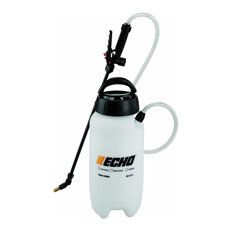
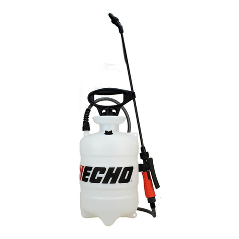
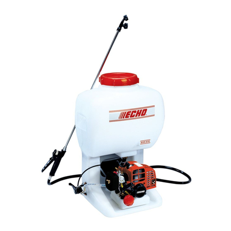
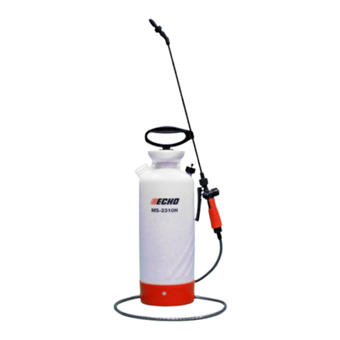
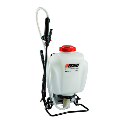
Echo MS-20 User manual

Handheld Tank Sprayer
Operator'sManual
MODELS MS - 20
MS - 35
99922203637
11/02
WARNING DANGER
Readrulesforsafeoperationandallinstructionscarefully. ECHOprovidesthis
Operator'sManualwhichmustbereadandunderstoodforproperandsafeoperation.

2
TABLE OF CONTENTS
Introduction ...................................................................... 2
Manual Safety Symbols and Important Information ......... 2
Safety Instructions ........................................................... 3
Specifications.................................................................... 4
Contents ........................................................................... 5
Description ....................................................................... 5
Assembly .......................................................................... 6
Operation .......................................................................... 6
Cleaning/Storage .............................................................. 7
Troubleshooting ............................................................... 7
Maintenance ..................................................................... 8
- PumpTubeO-ring ..................................................... 8
- Pump .......................................................................... 8
INTRODUCTION
Welcome to the ECHO family. This ECHO product was designed and manufactured to provide long life and on-the-job
dependability. Read and understand this manual before operation. You will find it easy to use and full of helpful operat-
ing tips and SAFETY messages.
THE OPERATOR'SMANUAL
Keep it in a safe place for future reference. Contains specifications and
information for safety, assembly, operation, maintenance, storage, and
troubleshooting specific to this product.
Specifications, descriptions and illustrative material in this literature are as accurate as known at the time of publication,
but are subject to change without notice. Illustrations may include optional equipment and accessories, and may not
include all standard equipment. Copyright© 2002 By Echo, Incorporated All Rights Reserved.
- SprayValveSpindle/O-rings...................................... 9
- Spray Gun Connector O-ring and Washer ................. 9
- Spray Hose .............................................................. 10
- AdjustableNozzle .................................................... 10
Sprayer Accessories ....................................................... 11
Accessories .................................................................... 11
ServicingInformation...................................................... 12
- Parts......................................................................... 12
- Service ..................................................................... 12
- ECHOConsumerProductSupport........................... 12
- Warranty Card ......................................................... 12
- Additional or Replacement Manuals ....................... 12
Handheld Tank Sprayer
Operator'sManual
MODELS MS - 20
MS - 35
99922203637
11/02
WARNING
DANGER
Readrules forsafe operationand allinstructions carefully. ECHOprovides this
Operator'sManual whichmustbe readandunderstood forproperand safeoperation.
Throughout this manual and on the product itself, you will find safety
alerts and helpful, information messages preceded by symbols or key
words. The following is an explanation of those symbols and key
words.
This symbol accompanied by the words WARNING and
DANGER calls attention to an act or condition that can lead to
serious personal injury to operator and bystanders.
The circle with the slash symbol means whatever is shown
within the circle is prohibited.
IMPORTANT
The enclosed message provides
information necessary for the protection
of the unit.
NOTE
This enclosed message provides tips for
use, care and maintenance of the unit.
MANUAL SAFETY SYMBOLS AND IMPORTANT INFORMATION

3
MS-20/MS-35 HANDHELD TANK SPRAYER
OPERATOR'SMANUAL
SAFETYINSTRUCTIONS
WARNING DANGER
Carefully read and understand the Operator’s Manual supplied with this unit prior to filling, using, and/or cleaning
this sprayer. DO NOT use flammables in the sprayer. They can ignite and explode. Always wear splash goggles and
all required protective gear and clothing when filling, using, cleaning, or performing maintenance on the sprayer.
Failure to follow all instructions can result in fire, explosion, and serious injury.
• Always inspect your sprayer thoroughly before and after each use. Check to be sure hose is securely attached and in
good condition before pressurizing the tank.
• Do not spray on or near electrical installations.
• Keep the work area clear of people and animals.
• Do not use sprayer when wind conditions cause spray to contact operator, plants, or other surfaces that may be harmed
by spray solutions.
• Wear a mask or respirator when filling, using, and cleaning sprayer, if recommended by the spray material manufacturer.
• Oil the pump tube tank seal o-ring prior to first usage so the o-ring will seal properly.
• Tighten all connections before using the sprayer. Connections may have loosened during shipping and handling.
• Always release pressure in the tank prior to filling, cleaning, or servicing the sprayer.
• Before opening a container of pesticide or other spray material, carefully read, understand, and follow all instructions on
thelabel.
• Never use caustic or corrosive chemicals which could damage the unit.
• Donot usehotliquids in sprayer. Maximum temperature30° C, 85°F.
• Do not drop a tank that has been pressurized. If tank is dropped, inspect immediately, and stop using if damaged.
• In case of personal contamination: remove contaminated clothing and get professional help immediately. Consult
chemical manufacturer's instructions for other important safety information.
• Never attempt to pressurize the unit by any other method than with the pump module provided. Never over-pressurize
the unit.
• Do not eat, drink, or smoke while spraying.
• Wash face and hands with soap and water after spraying.
• Clean and rinse tank and spray gun/wand assembly after each use to prevent crystallizing, and clogging or chemical
damage to the unit.
• Do not store sprayer under pressure, or with spray solution in tank.
• Do not transfer spray materials to other containers, especially food and/or drink containers.
• Keep spray materials locked up and out of reach of children and animals.
• Use only original manufacturer’s replacement parts.

4
SNOITACIFICEPS
LEDOM02-SM53-SM4-SM04-SM05-SM001-SM0012-RHS
EPYTREYARPSdlehdnaHdlehdnaHkcapkcaBkcapkcaBkcapkcaBkcapkcaBkcapkcaB
).laG(YTICAPACKNAT2.2 444 4.55.45
THGIEW.sbl6.sbl7.sbl8.9.sbl6.01.sbl2.21.sbl9.01.sbl1.71
SLAESnotiVlaicepSnotiVlaicepSnotiVlaicepSnotiVlaicepSnotiVlaicepSnotiVlaicepSnotiV
HTUOMKNAT"5.4"5.4"6"6"6"6"6
EPYTPMUPnotsiPnotsiPmgarhpaiDnotsiPlanretnInotsiPlanretnI /notsiP mgarhpaiD gnitalucriceR pmuPyratoR
REBMAHCERUSSERP YTICAPAC A/NA/N.zo04.zo4.52.zo4.72.zo04A/N
EPYTDNAWssarB"61ssarB"61ssarB"02ssarB"61ssarB"02ssarB"02ssarB"42
ELZZONTAYTICAPACWOLFMPG94.0MPG94.0MPG94.0MPG94.0MPG94.0MPG94.0MPG58.1ot4.0
ELZZONDRADNATSelbatsujdAelbatsujdA ssarB naF/tsujdA naFnaF ssarB naF/tsujdA daeHowT
GNITARERUSSERPISP04OT51ISP04ot51ISP07OT51ISP861OT51ISP861ot51ISP051OT51ISP541ot58
SNOITACILPPADEDNEMMOCER
ESABENIROLHCXX XX
SREZILITREF XXXXXXX
SEDICIBREH XXXXXXX
SEDICITCESNI XXXXXXX
SEDICITSEP XXXXXXX
*YARPSDESAB-LIO XXXXXXX
*YARPSDESAB-TNEVLOS XXXXXXX
*SRELAES/SNIATS XXXXXXX
SREDWOPELBAVLOSSIDXX**XXX X
.reyarpshtiwgniylppaerofebnoitamrofniytilibammalfrofsnoitcurtsnis'rerutcafunamkcehC* .stnetnocdeximfognilttestneverpotyrassecensinoitatigatneuqerf,sredwopdevlossidgniyarpsnehW**
SPECIFICATIONS

5
MS-20/MS-35 HANDHELD TANK SPRAYER
OPERATOR'SMANUAL
CONTENTS
_____ Tank Assembly With Hose & Spray Gun
_____ Spray Wand With Adjustable Nozzle
_____ ShoulderStrap WithPad
_____ Operator’sManual
_____ EchoLimitedWarrantyandWarrantyRegistrationforms
DESCRIPTION
1. PUMPHANDLE&TANKPUMP- Pump handleupanddowntopressurizetank. Turnhandlecounterclockwise to
remove pump, clockwise to tighten. Handle locks in position when turned. Use to carry or lift unit when locked in
position. Molded clip holds wand for convenient one-handed carrying of unit.
2. SHOULDER STRAP - Adjustable shoulder strap with cushioned pad supports sprayer for extended use.
3. SPRAY WAND - 16 in. heavy-duty brass design helps extend reach and directs flow for accurate spray delivery.
Adjustable nozzle allows spray adjustment from fine mist to solid stream. Screw-on connector permits rapid
assembly and removal for cleaning or replacement.
4. SPRAY GUN - Contains spray control lever and spray control valve. Provides secure hand grip for directing
spray. Spray lever locks in "On" position for continuous spraying. Spray valve cap permits easy access to spray
valve for cleaning. Accepts wide range of accessory spray wands - see "Accessories" section of manual.
5. SPRAY HOSE - Durable 4 ft. hose extends reach and provides easy maneuvering of spray gun and wand.
6. TANK - Durable corrosion-resistant tank features wide funnel mouth design for easy filling.
1
6
5
2
3
4

6
ASSEMBLY
1. Attach spray wand connector (A) to spray gun. Position nozzle
angle as desired, and tighten securely.
2. Hook the plastic clip attached to the shoulder strap into the
square opening in the base of the unit.
3. Tighten all hose and spray gun connections before using the
sprayer. Connections may have loosened during shipping and
handling.
A
OPERATION
1. Unscrew pump handle and remove pump from tank.
2. Mix spray solution in a separate container, following the chemical manufacturer's directions.
3. Pour pre-mixed solution through strainer into tank. Reinstall pump and tighten securely.
4. Turn pump handle counterclockwise to release handle from locked position.
5. Pressurize tank to desired pressure by pumping handle up and down. (Max. 35 to 40 times.)
6. Secure handle in down position by turning clockwise to locked position.
7. Adjust nozzle for desired spray pattern: Fine Spray - screw nozzle in clockwise. Stream - screw nozzle out counter-
clockwise.
8. Aim spray nozzle at desired area, and squeeze control lever to spray. For continuous spraying over large areas,
control lever may be locked in spray position.
9. Maintain desired pressure while spraying by pumping handle.
10. Release tank pressure before removing pump to refill or clean tank, or to perform any maintenance.
11. To release tank pressure, turn unit upside down. Aim spray nozzle in a safe direction, and squeeze control lever
until all air is released. Turn unit right side up, and unscrew pump.
12. Refill tank only with pre-mixed solution, and continue operation until spraying is completed.
13. When spraying is completed, release tank pressure as instructed above, and pour any remaining solution into a
properly marked container. Seal container securely, and store out of the reach of children. Dispose of any excess
solution according to chemical manufacturer's instructions. Clean unit immediately to prevent chemical deposits
fromforming.
NOTE
A unit that has been used with herbicides should never be used to spray insecticides, unless the sprayer has been
properly cleaned and all other chemicals neutralized. Failure to do this could cause you to kill plants that have been
sprayed. Consult with the manufacturer of the chemicals in use to obtain proper instructions.

7
MS-20/MS-35 HANDHELD TANK SPRAYER
OPERATOR'SMANUAL
TROUBLESHOOTING
MELBORPESUACNOITULOS
.ezirusserptonlliwreyarpS gnipmupdetaeperseriuqerknaT .erusserpetauqedaniatniamot
.pmupesooL .nrowroyrdgnir-oknatpmuP .pmalcesohesooL .eldnahlotsipyarpstaesoolesohyarpS .esoolrotcennocpirgnugyarpS "NO"dekcolrevelnugyarpS .nrowsgnir-oevlavkcehcpmuP .nekorbronrowevlavkcehcpmuP .nrow/yrdlaesregnulppmuP .nekorb/dekcarcebutpmuP .degamadrodekcarcknaT
.pmupnethgiT .gnir-oknatpmupecalperroetacirbuL .knatfomottobtapmalcesohnethgiT .rotcennocesohyarpsnethgiT .rotcennocpirgnugyarpsnethgiT .revelesaeleR .sgnir-oevlavkcehcecalpeR .evlavkcehcpmupecalpeR .laesregnulpecalper/etacirbuL .ebutpmupecalpeR .tinuecalpeR
.skaeldiulF.noitcennocesooL .laesdegamaD .rotcennocdekcarC .esohdegamadrodekcarC .knatdekcarC
.dedeensanethgitdnanoitcennockcehC .noitacolkaeltalaesecalpeR .rotcennocecalpeR .esohecalpeR .tinuecalpeR
.skcitsnipevlavyarpS.degamadsgnir-oevlavyarpS .aeraevlavyarpsnisirbeD .nekorbgnirpS
.sgnir-oecalpeR .aeraevlavyarpsnaelC .gnirpsecalpeR
nehwffotuhst'nseodyarpS .desaelersirevelyarps .degamadsgnir-oevlavyarpS .aeraevlavyarpsnisirbeD .nekorbgnirpS
.sgnir-oecalpeR .aeraevlavyarpsnaelC .gnirpsecalpeR
.kaewsiyarpS.erusserpknatwoL .dnawroesohnisirbedrotriD .deggulpteltuoknaT .degamadrodekcarcknaT
.eldnahpmuphtiwknatezirusserP .tinunaelC .teltuoknatnaelC .knatecalpeR
tnemtsujdaelzzonreyarpS .ylreporpkrowt'nseod .degamadroytridelzzoN .gnissimrodegamadsgnir-oelzzoN .wolerusserpknaT
.elzzonecalperronaelC .sgnir-oecalpeR .eldnahpmuphtiwknatezirusserP
hcaert'nseodtsim/maertsyarpS .aeraderised .dnawfoyticapacyarpsdnoyebaerA.tsilyrosseccaees-dnawregnolllatsnI
CLEANING/STORAGE
1. Release tank pressure. Remove pump, and pour out remaining solution. Clean all parts thoroughly according to
chemicalmanufacturer'sinstructions.
2. Add 1/2 gallon of fresh water to tank. Pressurize tank, and flush system by depressing trigger for at least two
minutes. Drain all remaining water from tank, hose, spray gun, and wand.
3. Always store tank clean and empty in a dry, shaded location.

8
PUMP TUBE O-RING
ToolsRequired: None
PartsRequired: PumpTubeO-ring, 10WOilorPetroleumJelly
1. Release tank pressure.
2. Unscrew pump from tank.
3. Remove o-ring (A) from underpumpshoulder.
4. Install new o-ring
5. Lightly lubricateo-ring.
6. Install pump in tank and tighten securely.
PUMP
ToolsRequired: Screwdriver
PartsRequired: PumpPlungerO-ring,PetroleumJelly
1. Release tank pressure.
2. Unscrew pump from tank.
3. Unscrew two (2) pump cap screws (B),and remove pump caps (C).
4. Pull pump handle assembly (D) out of pump tube (E).
5. Pull check valve assembly (G) out of pump tube bottom.
6. Check parts for wear or damage, and replace as needed.
7. Lubricate pump plunger o-ring (F), inside of tube (E), and check valve
o-ring(H) with petroleum jelly, and assemble parts in reverse orderof
removal. Pinch check valve prongs together at tips to insert check
valve in pump tube.
8. Check pump for proper operation. Check valve should allow air to
pass only on down stroke of pump handle.
NOTE
Lubricate pump plunger o-ring and inside of pump tube with a light
coating of petroleum jelly every 8 - 10 hours of operation.
A
BB
C
D
E
WARNING DANGER
Chemical contact hazard. Release tank pressure, empty tank, and wash unit before performing any maintenance
procedures. Wear splash goggles and all required protective gear and clothing required by chemical manufacturer.
Failure to follow all instructions may result in serious injuries.
MAINTENANCE
CC
F
EG
H
Consult parts catalog for part numbers of individual parts and repair kits. See "Servicing Information" section for instruc-
tions on obtaining a parts catalog.

9
MS-20/MS-35 HANDHELD TANK SPRAYER
OPERATOR'SMANUAL
SPRAY VALVE SPINDLE/O-RINGS
ToolsRequired: None
PartsRequired: SprayValveSpindleAssemblyorO-RingKit,
PetroleumJelly
1. Release tank pressure and remove pump. Squeeze spray lever to
allow fluid in hose and spray gun to drain back into tank, and empty
tank.
2. Unscrew spray valve cap (A). Check cap o-ring (B) for damage, and
replace if needed.
3. Remove valve spring (C) and spindle assembly (F) and check for wear
ordamage.
4. Replace spindle assembly,or install newseal (D) and o-rings(E) from
o-ringkit. Lubricatespindleo-ringslightlywithpetroleumjelly.
5. Inspect valve seat area of spray gun for buildup of chemical deposits
or debris, and clean as required.
6. Reassemble parts in reverse order of removal.
7. Tighten spray valve cap securely.
8. Check spray lever/spray valve for freedom of movement. Spray valve
spindle must return to closed position when lever is released.
9. Add water to tank, and test unit for leaks and proper operation before
adding spray solution.
SPRAY GUN CONNECTOR
O-RING AND WASHER
ToolsRequired: None
PartsRequired: Grip O-ring, Rubber Wand Washer
1. Release tank pressure and remove pump. Squeeze spray lever to
allow fluid in hose and spray gun to drain back into tank, and empty
tank.
2. Unscrew wand connector, and replace rubber wand washer (G).
3. Unscrew grip and replace gripo-ring(H).
4. Screw grip and wand connectors on tightly.
5. Add water to tank, and test unit for leaks and proper operation before
adding spray solution
A
B
C
E
D
G
H
F

10
SPRAY HOSE
ToolsRequired: Screwdriver
PartsRequired: Spray Hose Assembly
1. Release tank pressure and remove pump. Squeeze spray lever to
allow fluid in hose and spray gun to drain back into tank, and empty
tank.
2. Unscrew spray hose connector (A) from spray gun.
3. Loosen spray hose clamp (B) at base of unit, and remove hose from
tank outlet.
4. Attach new hose to outlet, and secure with hose clamp.
5. Screw hose connector to spray gun, and tighten securely.
6. Add water to tank, and test for leaks and proper operation before
adding spray solution.
ADJUSTABLE NOZZLE
ToolsRequired: Screwdriver,smalldiameterwire.
PartsRequired: NozzleAssemblyorNozzleO-ringKit,PetroleumJelly
1. Release tank pressure and remove pump. Squeeze spray lever to
allow fluid in hose and spray gun to drain back into tank, and empty
tank.
2. Unscrew nozzletip(E)fromwand.
3. Unscrew nozzle holder (G) and remove nozzle (C), and rubber washer
(F).
4. Check nozzle, nozzle o-ring (D), and rubberwasherfordamage,and
cleanor replace parts as required. Lubricate o-ring(D) lightly with
petroleumjelly.
5. If plugged, nozzle (C) canbe cleaned byinserting a small piece ofwire
into the nozzle opening to clear buildup.
6. Reassemble parts in reverse order of removal.
7. Add water to tank, and test unit for leaks and proper operation before
adding spray solution.
A
C
F
D
G
E
B

11
MS-20/MS-35 HANDHELD TANK SPRAYER
OPERATOR'SMANUAL
SPRAYERACCESSORIES
NUMBER DESCRIPTION
99944100220 66"BrassWand
99944100240 26"BrassWand
99944100080 Spray Shield - Small
99944100460 Spray Shield - Large
99944100310 16"BrassWand
99944100320 Adjustable Plastic Nozzle
99944100330 SprayGunAssembly
99944100340 AdjustableBrassNozzle
99944100350 Fan Spray Nozzle (Decks)
99944100360 Valve Regulator 14.5 psi
NUMBER DESCRIPTION
99944100370 Valve Regulator 21 psi
99944100380 Valve Regulator 29 psi
99944100390 Valve Regulator 44 psi
99944100400 Fiberglass Wand 20.5"
99944100410 Fiberglass Wand 39"
99944100420 Fiberglass Wand 60"
99944100430 Fiberglass Wand 78"
99944100440 Telescoping Fiberglass Wand
22.8"- 37"
99944100470 Universal spray gun, 16"
Brass wand and adjustable
brass nozzle (For all 3/8"
hose)

SERVICINGINFORMATION
PARTS
GenuineECHOPartsandECHOREPOWER™PartsandAssembliesfor
yourECHOproductsareavailableonlyfromanAuthorizedECHO
Dealer. When you do need to buy parts, always have the Model
Number of your unit with you. You can find this number on the tank.
For future reference, write the model number in the space provided
below.
Model No. _____________________________________
SERVICE
Service of this product during the warranty period must be performed
by an Authorized ECHO Service Dealer. For the name and address of
the Authorized ECHO Service Dealer nearest you, ask your retailer or
call:1-800-432-ECHO(3246). Dealerinformationisalsoavailableonour
Web Site. When presenting your unit for Warranty service/repairs,
proof of purchase is required.
ECHO CONSUMER PRODUCT SUPPORT
If you require assistance or have questions concerning the application,
operation or maintenance of this product you may call the ECHO
ConsumerProductSupportDepartmentat1-800-673-1558from8:30am
to4:30pm(Central Standard Time) Monday throughFriday.Before
calling, please know the model and serial number of your unit to help
your Consumer Product Support Representative.
WARRANTY REGISTRATION
You may register your Echo equipment using the warranty registration
card or register online at www.echo-usa.com. Registering provides a
direct link between you and ECHO if we find it necessary to contact
you.
ECHO, INCORPORATED
400 Oakwood Road
Lake Zurich, IL 60047
www.echo-usa.com
ADDITIONAL OR REPLACEMENT MANUALS
Operator'sandPartsManualsareavailableby:
• Downloadingfreefromwww.echo-usa.com
• PurchasingfromyourEchoDealer.
• Sendinga check or money orderfor $2.00 per Parts Catalog or $1.50
perOperator'sManualmadepayabletoECHO,INCORPORATED.
State on a sheet of paper the model number of the ECHO unit you
have, part number of the manual (if known), your name and address,
and mail to the address below.
Available Parts Catalog
MS-20/MS-35 PartNumber 99922203638
DEALER?
Call
1-800-432-ECHO
or
www.echo-usa.com
CONSUMER PRODUCT
SUPPORT
1-800-673-1558
8:30 - 4:30 Mon - Fri C.S.T.
This manual suits for next models
1
Table of contents
Other Echo Paint Sprayer manuals