echoflex Elaho User manual
Echoflex Installation Guide
Elaho Light Sensor
Ma in Office Squamish, BC, Canada Phone +1 778 733 0111
Email info@echoflexsolutions.com Web echoflexsolutions.com
© 2021 Echoflex Solutions, Inc. Trademark and patent info:echoflexsolutions.com/ip
Echoflex intends this document to be provided in its entirety.
Product information and specifications subject to change.
8186M2170 Rev D Released 2021-01
Overview
The Elaho Light Sensor provides light level measurement and lighting control
for the connected Elaho control system. The sensor measures lighting
conditions to maintain a programmed lighting output in both dimmed and
switched systems.
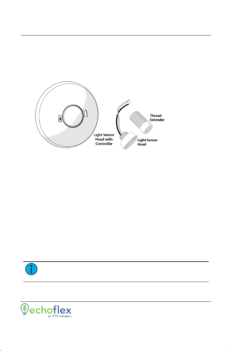
Light Sensors are available in three models:
•
E-LS - Light Sensor head with controller
•
E-LSC - Light Sensor controller only
•
E-LSH - Light Sensor head only
Each controller supports up to two Light Sensor heads. One head may be
installed within the controller, or both may be installed remotely. When using
a pair of Light Sensor heads, each transmits their light readings to a single
controller. The controller averages the received light levels and uses the
average to control the lighting within the space.
Custom Configuration
This document guides you through the installation and local DIP switch setup
of the sensor. For more detailed information about custom configuration
options available using ElahoAccess, see the ElahoAccess App integrated help
system.
Note:
To use the configuration settings applied using ElahoAccess,
DIP switch 2 must be enabled. See DIP Switch Settings on page9.
Echoflex Installation Guide
Light Sensor
Prepare for Installation
Ceiling-mount sensors are intended for installation to a finished ceiling
surface, soft ceiling tile mounted, or attached to a round or octagonal fixture
junction box. The Light Sensor remote head mounts directly into the
controller, to a conduit knockout, or into a soft ceiling tile using the provided
thread extender.
Compliance
•
cULus Listed
•
CE compliant
For use with Echoflex Elaho Control Systems, powered by an Elaho station
power supply.
Environment
Ambient
The controller ambient operating temperature range is 0to70°C
(32to158°F), with a non-condensing humidity. The Sensor head can be
installed remotely indoors or onto an outdoor weatherproof enclosure.
Ambient operating temperature range is -25to70°C(-13to158°F).
Wire Specification
The Light Sensor connects to the EchoConnect communication bus.
EchoConnect is a bi-directional protocol that uses one pair of wires (data+
and data-) for both data and power. Echoflex recommends using Belden
8471 Class 2 wire (or approved equal - see the Echoflex cable cross database
echoflexsolutions.com/files/Elaho_Data_Cable_Wire_Specs for equal
alternatives). The total combined length of an EchoConnect wire run using
Belden 8471 may not exceed 500m (1,640ft), with a maximum distance of
400m(1,312ft) between any two devices.
Note:
All control wiring should be installed and terminated by a
qualified installer and should follow standard wiring installation
practices. Leave approximately 25.4cm (10in) of wiring in the back
box for connection and to allow slack for future service needs.
Note:
Echoflex requires that all stations and devices be grounded for
ESDprotection. Pull an additional 2.5 mm2(14AWG) wire for
grounding when control wires are not installed in grounded metal
conduit.
Light Sensor Page 2 of 12 Echoflex
Echoflex Installation Guide
Light Sensor
Note:
When using Category 5 (or equivalent) cable on the
EchoConnect communication bus, please note the following:
•
Cat5 wiring must be terminated using EchoConnect Cat5
Termination Kit and must be installed using a bus topology.
Refer to the installation guide that is provided with the Cat5
Termination Kit (8186A1207) for information to terminate
Cat5 wiring.
•
Not all topologies are supported using Cat5; careful planning
is required to ensure the proper termination kits are available
and the wire is pulled appropriately.
Light Sensor Head
The controller provides termination for up to two Sensor heads. Each head
must be separately wired to the controller using no more than 304m
(1,000ft) of 1.5mm2(16AWG ) wire total per controller. These wire runs
must remain separate from EchoConnect wiring. Echoflex recommends using
Belden 8471 (or equivalent) wire.
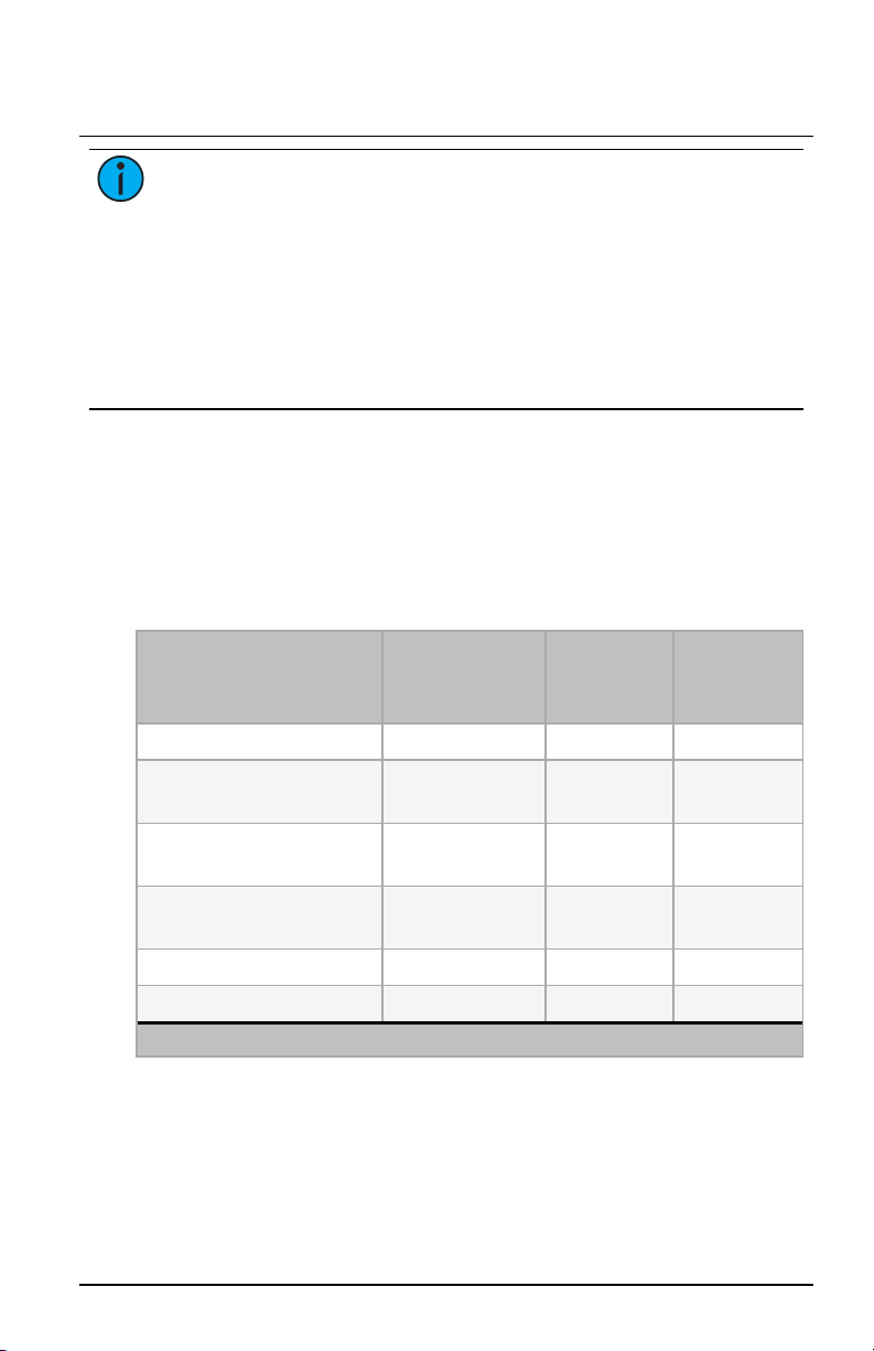
Supplies
Description
Sensorhead with
controller
(E-LS)
LightSensor
head
(E-LSH)
LightSensor
controller
(E-LSC)
Soft ceiling tile adapter X X
EchoConnect and ground
wire pigtails X X
Light Sensor head thread
extender X X
1 each nuts and washers
3/4in and 1in X X
2 each screws, 8-32x1-3/4 in X X
Blank Light Sensor head X X
Note: Use appropriately sized wire nuts (not provided) to secure each termination.
Light Sensor Page 3 of 12 Echoflex
Echoflex Installation Guide
Light Sensor
Installation
Note:
Installation must follow all national and local codes for
electrical equipment. NEC Class 2 product to be wired in accordance
to NEC Article 725 and local jurisdiction requirements.
The ceiling-mount sensor is provided with a mounting plate that can be
mounted to a junction box, finished ceiling, or soft ceiling tile. The Light
Sensor remote head mounts directly into the controller, to a conduit
knockout, or into a soft ceiling tile using the provided thread extender.
Determine the installation method and follow the detailed instructions:
•
Junction Box or Surface Installation below
•
Soft Ceiling Tile Installation on the facing page
•
Install Sensor Heads Remotely (optional) on page7
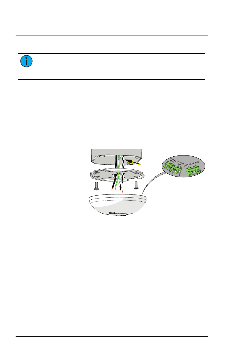
Junction Box or Surface Installation
Terminate all
wires here
Optional
Sensor wires
1. Pull the Belden
8471 (or
equivalent) and
one 2.5mm2
(14AWG) ground
wire to the
mounting
location (junction
box or finished
surface).
2. If you are installing the sensor in series with other sensors or
stations (continuing the data run), use the provided EchoConnect and
ESDground wire pigtails. Termination connectors are not provided. If
you are not continuing the data run, direct termination to the
sensor controller is recommended, skip this step and proceed to
step3.
a. Strip each wire to the appropriate length, depending on the wire
nut or other termination used (wire nuts are not provided).
b. Twist the incoming data-EchoConnect wire(typically black) and
the data-wire(black) from the EchoConnect pigtail as well as any
continuing data-EchoConnect wire together and secure with a
wire nut.
c. Repeat the above step for the data+EchoConnect wire(typically
white) and for the ESD ground wire (typically green/yellow), using
a new wire nut for each termination type.
Light Sensor Page 4 of 12 Echoflex
Echoflex Installation Guide
Light Sensor
3. If you are installing the primary and/or optional second Sensor head
external from the controller, see
Install Sensor Heads Remotely
(optional) on page7
and then return to these instructions. If you are
not installing Sensor heads remotely, proceed with this instruction.
Note:
All sensor wires must terminate directly to the terminals at the
controller.
4. Orient the flat side of the mounting plate to the junction box and pull
all incoming wires from the junction box through the provided holes
near the center of the mounting plate.
5. Secure the mounting plate to the junction box using the screws
provided.
6. Terminate EchoConnect and ESD ground wires to the EchoConnect
terminal block on the sensor controller. Torque each terminal 3.1-
3.5in-lb.
a. Strip each wire 8mm (5/16in).
b. Insert the data+ (typically white)EchoConnect wire into the
data+ terminal and secure.
c. Insert the data- (typically black) EchoConnect wire to the data-
terminal and secure.
d. Insert the green/yellow (ground) wire into the ground terminal
and secure.
7. Terminate the remote Sensor head wires to the provided terminals. See
Terminate Sensor Head Wiring on page8
.
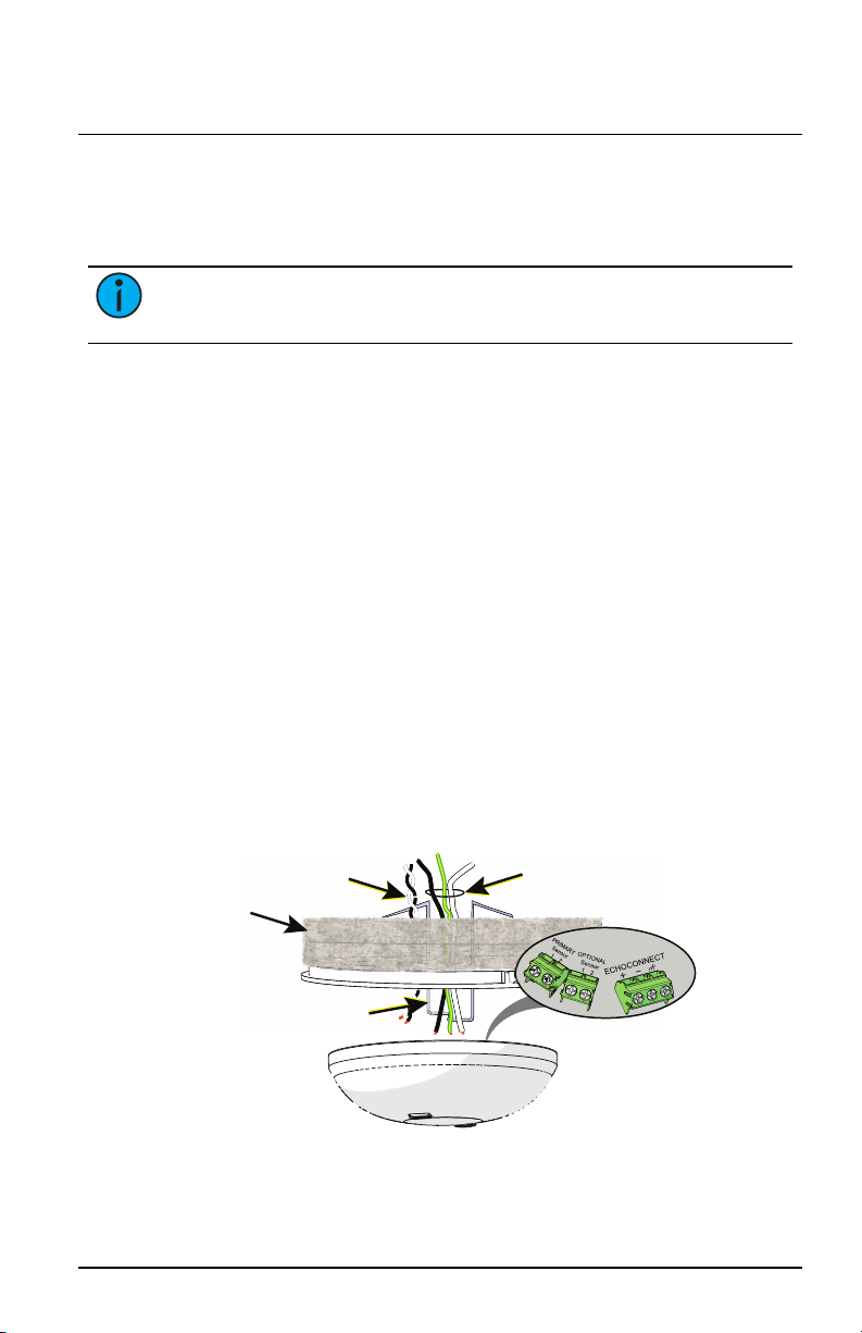
Soft Ceiling Tile Installation
EchoConnect and ESD
Ground pigtails
(optional use)
Terminate all
wires here
Optional
Sensor wires
Ceiling
tile
Ceiling tile
adapter
Light Sensor Page 5 of 12 Echoflex
Other manuals for Elaho
3
Table of contents
Other echoflex Accessories manuals

echoflex
echoflex TAP-31 User manual

echoflex
echoflex TAP-21 Series User manual

echoflex
echoflex Elaho Dual Tech Wall-mount Vacancy Sensor User manual

echoflex
echoflex OWS User manual

echoflex
echoflex MC-31 User manual

echoflex
echoflex MOS-17 User manual

echoflex
echoflex FLS-41 User manual

echoflex
echoflex Elaho Dual Tech Ceiling-mount Vacancy Sensor User manual

echoflex
echoflex MOS-21 Series User manual

echoflex
echoflex ERUSB-C User manual


