echoflex RVS-A-xW User manual

RVS/RCS
This guide covers Resonate Vacancy/Occupancy sensor models, RVS-A-xW,
RVS-B-xW, RCS-A-xW and RCS-B-xW. The RCS is idencal to the RVS with the
addion of a baery to provide power for support of auto-on occupancy sensor
applicaons.
The character x in the model number is replaced with U for 902MHz, Y for
868MHz radios, and J for 928MHz radios.
The package includes the sensor, installaon guide, lens mask scker and two
wire adaptor straps for so ceiling le mounng. The cover is removable. Please
note: the cover must be fully seated for proper operaon.
The RVS/RCS (also referred to as the sensor in this guide) is a wireless, energy
harvesng sensor that monitors room occupancy state using a passive infrared
moon (PIR) detector. The RVS/RCS sensors are intended for indoor use only,
mounted on a ceiling at 8-10 feet from the oor.
NOTE: The RVS is a solar powered device that absorbs solar energy from arcial or
natural light sources. Before assigning the RVS sensor to a receiver or controller, the
sensor should be exposed to a good light source for a minimum of 2 minutes.
Installaon Guide
echoflex
Powered by ETC

2
The RVS sensor is powered by solar energy from natural or arcial light sources.
The solar energy is transformed into electrical energy which is then used
as a power source for the sensor. Powered by two solar cells, the sensor will
begin operaon without a baery within 2 minutes of being in sucient light.
The sensor will operate with 6 foot candles (65 lux) light energy. The RCS has
instantaneous operaon (baery powered).
The moon sensor supports the Occupancy Sensor EnOcean prole A5-07-01.
The sensor will transmit occupancy or vacancy depending on the occupancy
state of the room. The sensor will broadcast occupancy immediately upon a
state change from vacant to occupied. The sensor broadcasts a telegram when
movement is detected and repeats occupied telegrams with a minimum 100
second period between subsequent transmissions.
Aer detecng moon, the sensor is shut-down to conserve energy for 100
seconds. When the sensor awakens and further moon is detected, the sensor
will transmit an occupied telegram. If no moon is detected within 100 seconds,
the sensor transmits a vacancy telegram, 200 seconds total since the previous
transmission. The sensor will remain acve unl the next occupancy state is
triggered by moon detecon. If the sensor does not detect moon, it resends
the vacancy telegram every 1000 seconds.
The sensors use a PIR sensor element that detects moon by measuring the infrared
energy emied by objects. The sensors are calibrated to detect the temperature
range of the human body. The sensor has a lens that breaks the viewing angle of the
sensor into zones (movement zones), infrared energy moving in and out of a zone
is how the occupied state is dened. The amount of movement that triggers the
sensor is dependent upon the density of the zones where the moon takes place. A
Lens B: use for large moon detecon or larger rooms.
8/2.4m
30/9.1m 20/6m 10/3m 010/3m 20/6m 30/9.1m
10/3m
0
8/2.4m
15/4.5m
10/3m 5/1.5m 05/1.5m 10/3m
15/4.5m
10/3m
0
8/2.4m
15/4.5m 10/3m 5/1.5m 05/1.5m 10/3m 15/4.5m
10/3m
0
Lens A: use for small moon detecon or small rooms.

3
higher density of zones means smaller moon will trigger the sensor.
For detecon of small moon (typing, drinking from a coee cup), use the A
lens which has more movement zones. Place the sensor close to the locaon
where the moon may occur.
The sensor comes with a scker that can be applied to the lens to mask o areas
where moon detecon is not desired.
An LED under the lens will blink once every 100 seconds when the sensor is
detecng moon. Addionally, the LED color indicates the status of the baery
when applicable, see the following table.
Red No baery or weak
Amber 50% discharged
Green Full charge
The mounng locaon of the sensor is important as this will directly aect the
receivers’ recepon of the telegrams. Before installing, refer to the secons
in the guide detailing the installaon of wireless devices, layout ps and test
operaon modes.
NOTE: The sensor cannot detect occupancy through solid objects including items placed
by a tenant, such as le cabinets or shelves.
NOTE: Do not locate the sensor near forced air vents as hot moving air may cause
the sensor to false trigger. Leave at least 4’ (1.2 m) minimum between air vents and
the sensor.
NOTE: Incandescent lights may cause false trips when turning on.
1. Select a locaon to mount the sensor on the ceiling by idenfying the
movement paerns that will be the most common in the space.
• For smaller oce spaces where hand moon on a desktop is common,
locate the sensor o to one end of the desk, in line with the desk edge
or slightly behind so the PIR lens has direct line-of-sight to the keyboard
desktop area. Insure that the PIR lens does not have direct line-of-sight
out a doorway where walk-by trac could trigger the sensor. Use the
included lens mask sckers to mask o these areas.
• Larger oces where larger body moon is more common, placement of
the sensor is less crical.
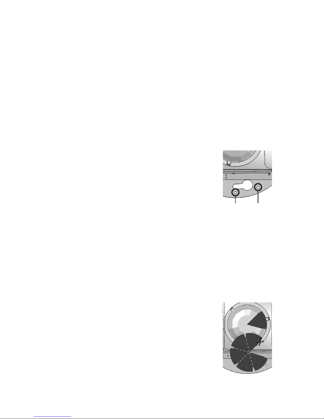
2. For the best sensor performance, mount the RVS sensor so at least one of
the solar cells is facing a light xture. The sensor will operate in low light
levels however, for best performance; a minimum of 6 foot candles must
be maintained. If the controlled lights in the space are dimmable either
manually or via daylight harvesng, insure the light level at the lowest
dimmed level meets this 6 FC requirement. If the light value does not meet
this requirement, install a baery.

4
3. Remove the cover by inserng a small screwdriver under the white
enclosures lip. Gently twist the screw driver and pull the cover away from
the base.
4. Choose a mounng method. The RVS/RCS sensor can be mounted:
• With the integrated magnets to a steel T-bar ceiling frame or other
metallic surface by placing the sensor on to the metal rail.
• With screws and anchors (not provided) to a wall-board ceiling.
i. Use a pencil to mark the mounng base keyhole locaons and
remove the sensor.
ii. Using a drill, bore the two holes and insert the anchors.
iii. Install the screws, leaving them loose while you place the sensor.
iv. Tighten the screws.
• With the provided wire adapter straps to a so ceiling le.
i. Mark the sensor mounng locaon on the
ceiling le with a pencil. Remove the ceiling le
from the T-bar frame.
ii. Insert the so ceiling le adapters through the
pair of small holes beside both keyholes on the
sensors mounng plate.
iii. Poke the adapter nes through the ceiling le,
then bend each ne over in opposite direcons for
a secure t.
iv. Replace the ceiling le.
• With double sided tape or Velcro™, not provided. Cut two lengths of
tape and remove the backing. Place on the mounng surface of the
sensors back plate, pressing down. Remove the backing from the tapes
other side and place the sensor on the ceiling surface, pressing rmly.
5. Refer to the secon tled.
6. Once linking is complete, replace the sensor cover.
seated. If the cover is not rmly aached, it could obstruct the lens and
adversely aect operaon.
Lens mask sckers are provided in the packaging for
your convenience.
1. As needed, peel o the lens masks to t the desired
area to be blocked.
2. Apply the mask gently to the secon of the lens exterior
to block the required area from occupancy sensing.
This process requires the controller or receiver to be mounted,
powered and within range of the sensor to be linked.
Lens Mask Applied
Wire Mounts

5
The sensor is a solar powered device that absorbs energy through a solar panel;
storing it for use during low light periods. Before assigning the sensor to a
receiver/controller, the RVS must be exposed to a good light source for at least
2 minutes.
1. Remove the cover by inserng a small screwdriver under the white
enclosures lip. Gently twist the screw driver and pull the cover away from
the base.
2. Acvate LEARN or LINK mode at the receiver, if necessary refer to the
manufacturers documentaon.
3. Press the sensors LINK buon.
4. Deacvate LEARN mode at the receiver.
The baery is not required for normal
operaon when the RVS receives
adequate natural or arcial light,
minimum 6 foot candles or 65 lux.
The RCS model comes with a baery
(requires installaon).
1. Remove the cover by inserng a small
screwdriver under the white enclosures lip. Gently twist the screw driver
and pull the cover away from the base.
2. To remove an old baery, use a small screwdriver as a lever and insert
under the baery. Gently twist the screwdriver so the baery pops out.
3. Install or replace the baery with a new CR1632 coin cell baery insuring
the posive side (+) will be facing up.
4. Place the baery in the holder and press in place with your thumb.
Test modes require a baery to be installed. For RVS units, insert a CR1632
baery to run tests.
NOTE: An alternave to installing a baery is to use a bright light (hand-held
LED light, or Smart Phone) and shine this on the sensor while in test mode.
Depending on the light used, this may provide sucient energy to run the test
selected. Do not use this method for Light Level Test, Walk Test Mode or Range
Conrmaon .
Remove the cover for access to the test buon.
The following 4 tests can be selected when in test mode operaon.
1. To enter Light Level Test mode, press and hold the test buon for 6 seconds.
The green LED will begin to blink (LEDs are located under the lens).
2. Press the test buon again for 6 seconds to select Light Level Test. The
green LED will blink in accordance to the light level it is detecng. This will
Baery Holder
Link Buon

6
change (2 second lag me) if you move the sensor to areas with dierent
light levels. See blink indicator table on the next page.
The green LED will blink according to the energy produced by the solar cell
Lux
0 0 0 below operang level
150-100 4.5 to 9 min. operang level
2100-200 9 to 18 operaonal
3200-400 18 to 36 operaonal
4400-800 36 to 72 operaonal
5 800+ 72+ operaonal
The test will repeat every 2 seconds and run for a duraon of 100 seconds. You
may quit the test at any me by pressing the Test buon for 10 seconds.
provides visual feedback of the sensors signal
strength by a linked receiver with range conrmaon capability (only “F series”
controllers have range conrmaon ability). Have only one receiver linked to the
sensor for proper operaon of the test and disable repeaters in range for proper
test operaon).
The Range Conrmaon test requires a baery to be installed.
1. To enter Range Conrmaon Test mode, press and hold the test buon for
6 seconds. The green LED will begin to blink.
2. A quick press and release of the buon at this point will allow you to select
between test modes. Pressing and releasing the test buon scrolls through
the LED indicators. When the amber LED is blinking, go to step 3.
3. Press and hold the test buon again for 6 seconds to select Range
Conrmaon Test.
4. All three LED’s will blink (for 1 second) in this test mode when the sensor
transmits or receives a Range Conrmaon Telegram followed by the
sensor displaying the linked signal strength status for 2.5 seconds.
LED
Green - Blinking 2.5 sec -41 to -70 dBm
Amber - Blinking 2.5 sec -70 to -80 dBm
Red - Blinking 2.5 sec -80 to -95 dBm
No LED No linked receivers detected
The test will repeat every 4 seconds and run for a duraon of 50 seconds. You
may quit the test at any me by pressing the test buon for 10 seconds.
: In walk test mode, the red LED will blink on every moon event.
This allows an installer to verify the sensor can monitor and detect moon in an
area as required.
1. To enter Walk Test mode, press and hold the Test buon for 6 seconds. The
green LED will begin to blink.

7
2. A quick press and release of the buon at this point will allow you to select
between test modes. Pressing and releasing the test buon scrolls through
the LED indicators. When the red LED is blinking, go to step 3.
3. Press and hold the test buon again for 6 seconds to select Walk Test
mode. The red LED will begin blinking when moon is detected. The test
will run for a duraon of 100 seconds. You may quit the test at any me by
pressing the test buon for 10 seconds.
The sensivity feature allows the installer to adjust
the sensivity level. False occupancy states caused by other elements can be
reduced by reducing the sensivity level. The default seng is max. sensivity.
To enter sensivity adjust mode, press and hold the Test buon for 6 seconds.
The green LED will begin to blink.
1. A quick press and release of the buon at this point will allow you to
select between test modes. Pressing and releasing the test buon scrolls
through the LED indicators. When the red and amber LEDs are blinking
simultaneously, go to step 2.
2. Press and hold the test buon again for 6 seconds to select PIR sensivity
adjust mode. One of the LEDs will begin blinking based on the selected
sengs, see the .
3. A press and release of the buon will allow you to scroll through the
sengs as shown in the sensivity adjust table on page 7.
High Green LED blinking
Medium Amber LED blinking
Low Red LED blinking
NOTE: The low sensivity seng is used as the base line for the lens detecon ray
diagrams found on the data-sheet.
4. To select a seng press and hold the test buon for 10 seconds when the
desired LED is blinking. To exit without saving, allow the test to me-out in
60 seconds.
Careful planning is needed when locang the receivers and transmiers based
on the construcon materials in the space and possibility of tenant’s furniture
disrupng the transmissions.
The occupancy sensor should be installed in the space where the receiver is
mounted and connected to the occupancy control equipment. The signal will
travel through some material barriers.
Refer to the tables on the next page for range consideraons with building
materials that reduce the radio signal power.

8
Wood 0 - 10%
Plaster 0 - 10%
Glass 0 - 10%
Brick 5 - 35%
MDF 5 - 35%
Ferroconcrete 10 - 90%
Metal 90 - 100%
Aluminum 90 - 100%
Avoid locang transmiers and receivers on the same wall.
Avoid locang transmiers and receivers where the telegrams must penetrate
walls at acute angles. This increases the material the telegram must pass through
reducing the signal power.
Avoid large metal obstrucons as they create radio shadows. Place receivers in
alternate locaons to avoid the shadow or use repeaters to go around the obstacle.
Do not locate receivers close to other high frequency transmiers.
Leave at least 3’ between the receiver and any other source of interference
including, ballasts, LED drivers, computers, video equipment, Wi-Fi/LAN
routers, GSM modems and monitors. Transmiers are not aected by these
sources of interference.
echoflex
Powered by ETC
#1, 38924 Queens Way | Squamish | BC | Canada | V8B 0K8
Toll Free: 888-324-6359 | Phone: (778) 733-0111 | Fax: (604) 815-0078
Email: info@echoexsoluons.com | www.echoexsoluons.com
Copyright 2015-2017 Echoflex Solutions, Inc. | Specifications subject to change without notice.
Document 8DC-5543 | Revision 1.6| 8188M21-5543-1 | Rev E
CEC Title 24 Compliant
Built in an ISO9001 cered facility
FCC Part 15.231 (902 MHz models only)
Contains FCC ID: TCM300U
The enclosed device complies with Part 15 of the FCC Rules.
Operaon is subject to the following two condions:
(I.) this device may not cause harmful interference and
(ii.) this device must accept any interference received, including
interference that may cause undesired operaon.
IC RSS-210(902 MHz models only)
Contains IC: 5713A-STM300U
CE (868 MHz models only)
CE Marking
ARIB STDT108 (928MHz models only)
Complies with the Japanese radio law and is cered according to ARIB STDT108.
This device should not be modied (otherwise the granted designaon
number will become invalid)
Line of sight: 80’ (24m) corridors
Line of sight: 150’ (46m)open halls
Plasterboard: 80’ (24m) through 3 walls
Brick: 33’ (10m) through 1 wall
FerroConcrete: 33’ (10m) through 1 wall
Ceiling: not recommended
This manual suits for next models
3
Table of contents
Other echoflex Accessories manuals

echoflex
echoflex ERUSB-C User manual

echoflex
echoflex FLS-41 User manual

echoflex
echoflex RVS-A-xW Series User manual

echoflex
echoflex MOS-17 User manual

echoflex
echoflex RVS-A-XW User manual

echoflex
echoflex Elaho User manual

echoflex
echoflex Elaho Dual Tech Wall-mount Vacancy Sensor User manual

echoflex
echoflex Elaho Dual Tech Ceiling-mount Vacancy Sensor User manual

echoflex
echoflex Elaho User manual

echoflex
echoflex TAP-17 User manual