echoflex TAP-21 Series User manual
TAP-21
Installaon Guide
Overview
This guide covers all models of TAP-21 sensor.
The TAP-21 product family includes:
• TAP-21U Photo Sensor with 902 MHz radio
• TAP-21Y Photo Sensor with 868 MHz radio
• TAP-21J Photo Sensor with 928 MHz radio
The package includes the photo sensor and installaon guide.
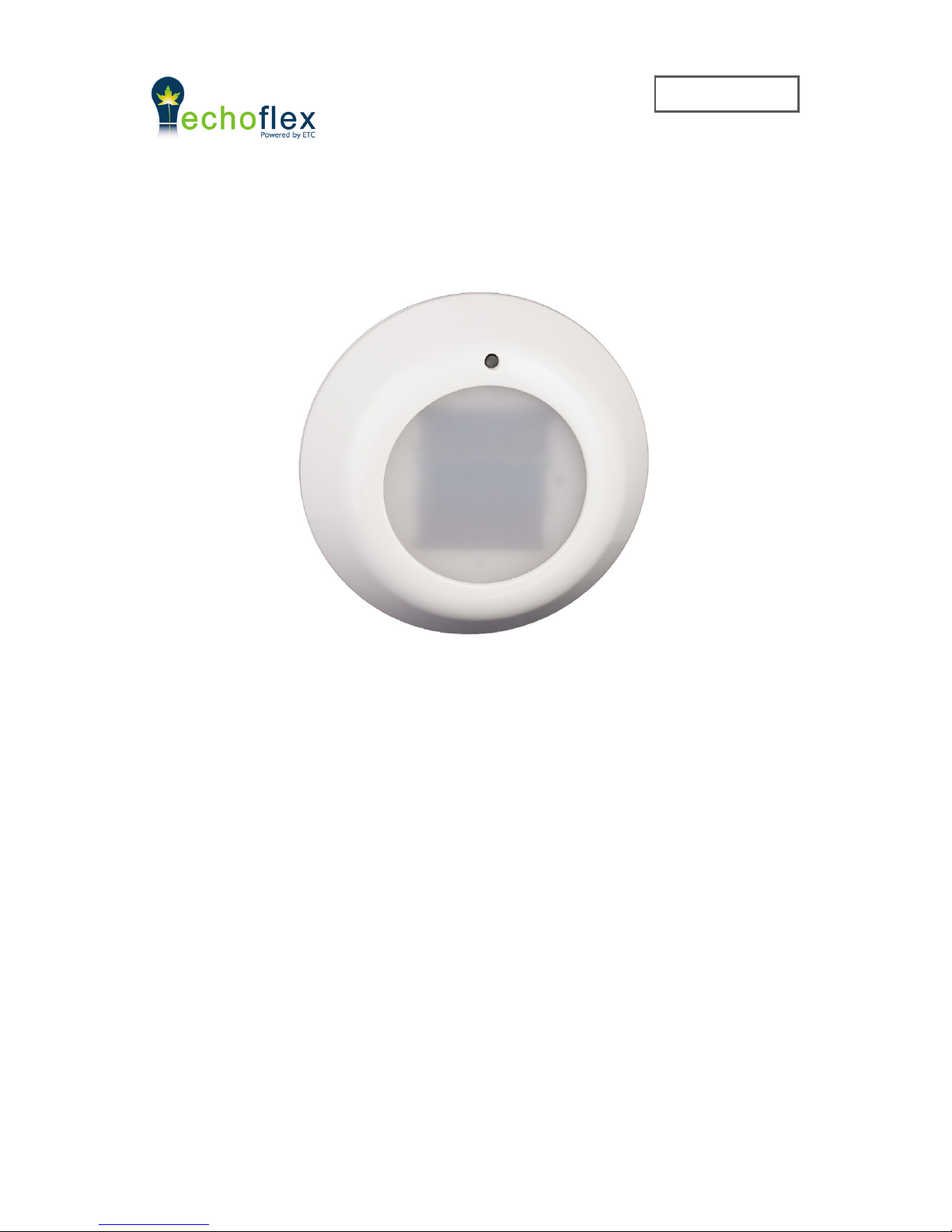
The 21 series TAP Task Ambient Photo sensor (also referred to as the sensor
in this guide) is a wireless, energy harvesng sensor that monitors light levels
within interior spaces and transmits the value to lighng controllers.
The sensor measures ambient light in two ranges: 0-510 lux (0 - 50 foot candles)
and 0-1024 lux (0 - 100 fc) and is intended for indoor use only.
NOTE: The TAP is a solar powered device that absorbs solar energy storing it for use
during low light periods. Before assigning the TAP device to a receiver/controller, the
device should be exposed to a good light source for a minimum of 5 minutes or install a
start assist baery.

2

3
The Task Ambient Photo (TAP) sensor monitors interior light levels. The TAP
sensor is powered by solar energy from natural or arcial light sources. The
solar energy is transformed into electrical energy which is then stored, providing
a connuous power source for the sensor. The sensor will operate even with a
brief exposure to light, however for best results the sensor should be mounted
in a locaon with exposure of 3-6 hours of natural or arcial light (250 - 500 lux
or 25-50 fc) on a daily basis.
The sensor transmits telegrams containing the light level and storage capacitor
voltage level. The sensor must be within range of any linked receivers or
controllers, installed within 24m (80’) of each other. For applicaons exceeding
24m (80’) range, telegram repeaters may be needed to extend the recepon
range.
The photo sensor supports the following Sensor prole:
DB_1: 0 lux - 1024 lux
DB_2: 0 lux - 512 lux
DB_3: Supply Voltage 0…5.1V, linear n=0…255
The sensor will repeatedly broadcast a telegram on a mer (heart beat mer).
The me period adjusts automacally to the ambient light levels and energy
charge stored on the radio.
Timer
< 50 lux (5 fc) 100 seconds
> 50 lux (5 fc) linear ramp from 60 to 10 seconds (as
device approaches full charge)
The sensor can be mounted on any
surface; ceiling, wall, desk, cubicle
wall, etc.
The mounng locaon of the sensor
is important as this will directly
aect the receivers recepon of the
telegrams. Before installing, refer to
the secons in the guide detailing the
installaon of wireless devices, layout
ps and test operaon modes.
The sensor should be placed so there
is direct exposure to a window. The
most common mounng locaon for
photo sensors is ceiling mount, centered with the window, about 4’ from the

4
window. The sensor must be installed in the space where the receiving lighng
controller is operang the light xtures. See the secons on light level test and
range conrmaon* to aid in opmal placement. * -(requires F series Echoex
controller)
The sensor can be mounted using screws (not supplied) through the back plate
or using double-sided tape or Velcro™ (not supplied).
This process requires the controller or receiver to be mounted and powered and
within range of the sensor to be linked.
1. Acvate LEARN or LINK mode at the receiver, if necessary refer to the
manufacturers documentaon.
2. Tap the sensors TEACH buon.
3. Deacvate LEARN mode at the receiver.
1. Using a ngernail or small at head screwdriver, pop the rear mounng
plate o the sensor to reveal the range slide switch.
2. Slide the switch to the range seng required, 512 lux (50 foot-candles) or
1024 lux (100 foot-candles). The factory default is 512 lux.
3. Press the rear mounng plate back into posion.
The baery is not required for normal operaon. The baery may be useful
for installaon purposes (when using the Range Conrmaon test and Daylight
Harvesng test mode, which depletes the energy stores of the TAP quickly.)
1. Using a ngernail or small at head screwdriver, pop the rear mounng
plate o the sensor.
2. To remove old baery: Using a small at head screwdriver or pen as a lever,
insert pointed end under the baery’s edge and pop out of the holder.
3. Install or replace the baery in the clip with a new CR2032 coin cell baery
insuring the baery edge is under the retaining clip and posive side (+) is
facing up.
4. Press on the rear mounng plate unl it snaps back into posion.
The following tests can be selected when in test mode.
1. Light level test
2. Range conrmaon test
3. Daylight harvesng test mode
This test provides visual feedback of the
immediate energy produced by the solar panels.

5
5
1. To enter Light Level Test mode, press and hold the teach buon unl the
green LED begins to blink (about 6 seconds - LEDs are located on right hand
side of the solar panel).
2. Press and hold the teach buon again unl the green LED stops blinking,
about 6 seconds. The green LED will start blinking faster in accordance to
the light level it is detecng, see tables below.
0< 50 <5 below operang level n/a
1< 142 <14 48.0 hours 67.0 hours
2< 234 <23 26.5 hours 82.5 hours
3< 326 <33 18.0 hours 86.75 hours
4< 418 <42 13.25 hours 88.75 hours
5>418 >42 11.0 hours 90.0 hours
0< 50 <5 below operang level n/a
1< 244 <24 26.0 hours 82.5 hours
2< 438 <44 12.5 hours 89.25 hours
3< 632 <63 10.0 hours 90.75 hours
4< 826 <83 9.5 hours 91.0 hours
5> 826 >83 9.0 hours 91.25 hours
The me to fully charge is based on the storage capacitor charging from a non-
operaonal condion. Discharge me indicates how long a fully charged sensor
will operate in the dark. The test will repeat every 2 seconds and run for a
duraon of 100 seconds. You may quit the test at any me by pressing the teach
buon for 6 seconds.
This test provides visual feedback of the sensors
signal strength by a linked receiver with range conrmaon capability.
Note:
• Range Conrmaon only available with “F series” Echoex Controllers.
• The TAP must be at full charge and/or have the baery installed for Range
Conrmaon Tests energy requirements.
• Only one receiver can be linked to the sensor for proper operaon of the test.
• Disable repeaters in range for proper test operaon.
1. To enter Range Conrmaon Test mode, press and hold the teach buon
unl the green LED begins to blink (about 6 seconds).
2. A quick press and release of the buon at this point will allow you to select
between test modes. Pressing and releasing the test buon scrolls through
This manual suits for next models
3
Table of contents
Other echoflex Accessories manuals

echoflex
echoflex Elaho User manual

echoflex
echoflex Elaho Dual Tech Wall-mount Vacancy Sensor User manual

echoflex
echoflex TAP-31 User manual

echoflex
echoflex RVS-A-xW User manual

echoflex
echoflex RVS-A-xW Series User manual

echoflex
echoflex Elaho Dual Tech Ceiling-mount Vacancy Sensor User manual

echoflex
echoflex MOS-17 User manual

echoflex
echoflex TAP-21C User manual

echoflex
echoflex TAP-17 User manual

echoflex
echoflex MOS-21 Series User manual


