EcoFlow PowerOcean LFP Battery User manual

Ecoflow PowerOcean LFP Battery
USER MANUAL
V1.1
POWEROCEAN LFP BATTERY
CONNECTION COM BAT JUNCTIONBOX
JUNCTION BOX
POWEROCEAN LFP BATTERY

CONTENTS
1 Safety Instructions
1 Disclaimer
1 Statement
1 Symbol Conventions
1 General Requirements
1 Personnel Requirements
1 Electrical Safety
2 Battery Safety
2 Transportation Requirements
2 Installation Environment
Requirements
3 Equipment and Personnel
Safety Requirements
3 Product Introduction
3 Function
3 Battery Capacity Description
3 Networking Application
4 Appearance
4 Label Description
5 Features
5 System Modes
5 Self-Powered Mode
6 Checking before the
Installation
5 Checking Outer Packing
5 Checking Deliverables
System Installation
Electrical Connection
5 System Commissioning
5 System Power-on
6 System Maintenance
6 System Power-Off
6 Routine Maintenance
6 Battery Storage and Recharge
7 Replacing a fuse
7 Used Batteries Disposal
8 Technical Parameters

Safety
Instructions
This is a safety warning symbol. Such safety information alerts you
to hazards that can be lethal to you and others, and that can cause
damages to the equipment. All safety information is preceded by safety
warning symbols and hazard words, including: "DANGER", "WARNING",
"CAUTION", and "NOTICE". The "DANGER", "WARNING", "CAUTION",
and "NOTICE" statements in this manual do not cover all the safety
instructions. They are only supplements to the safety instructions.
SYMBOL CONVENTIONS
This manual contains important safety and operating instructions. Before
installation, operation, and maintaining the equipment, read this manual
and observe all the safety instructions on the equipment and in this
manual.
Ensure that the equipment is used in environments that meet its design
specifications. Otherwise, the equipment may become faulty, and the
resulting equipment malfunction, component damage, personal injuries, or
property damage are not covered under the warranty.
Follow local laws and regulations when installing, operating, or
maintaining the equipment. The safety instructions in this manual are only
supplements to local laws and regulations.
EcoFlow will not be liable for any consequence caused by the violation
of general safety requirements or design, production, and usage safety
standards.
STATEMENT
Read this user manual carefully before using the product to ensure that
you completely understand the product and can correctly use it. After
reading this user manual, keep it properly for future reference. Improper
use of this product may cause serious injury to yourself or others, or cause
product damage and property loss. Once you use this product, it is deemed
that you understand, approve and accept all the terms and content in this
document. EcoFlow is not liable for any loss caused by the user's failure to
use this product in compliance with this user manual.
In compliance with laws and regulations, EcoFlow reserves the right to
final interpretation of this document and all documents related to this
product. This document is subject to changes (updates, revisions, or
termination) without prior notice. Please visit EcoFlow's official website to
obtain the latest product information.
DISCLAIMER
Symbol Description
Indicates a hazard with a high level of
risk which, if not avoided, will result in
death or serious injury.
Indicates a hazard with a medium level
of risk which, if not avoided, could result
in death or serious injury.
Indicates a hazard with a low level of
risk which, if not avoided, could result in
minor or moderate injury.
Indicates a potentially hazardous
situation which, if not avoided, could
result in equipment damage, data
loss, performance deterioration, or
unanticipated results.
NOTICE is used to address practices not
related to personal injury.
NOTICE
DANGER
WARNING
CAUTION
1
GENERAL REQUIREMENTS
DANGER
•Do not work with power on during installation.
1. If the power cord of this equipment is damaged, it must be replaced by the
manufacturer, customer service department or qualified personnel to prevent
a safety hazard.
2. Do not touch the exposed cable with your hands.
3. Make sure the cables, connectors and ports are dry before starting up the
equipment. Make sure all three are connected securely.
4. Do not install, use, or operate outdoor equipment and cables in harsh weather
1. Personnel who plan to install or maintain EcoFlow equipment must receive
thorough training, understand all necessary safety precautions, and be
able to correctly perform all operations.
2. Only qualified professionals are allowed to install, operate, and maintain
the equipment.
3. Personnel who will operate the equipment, including operators, trained
personnel, and professionals, should possess the local national required
qualifications in special operations such as high-voltage operations,
working at heights, and operations of special equipment.
PERSONNEL REQUIREMENTS
Professionals: personnel who are trained or experienced in equipment
operations and are clear of the sources and degree of various potential
hazards in equipment installation, operation, and maintenance.
conditions such as lightning, rain, snow, and level 6 or stronger wind.
5. Tighten the screws to the specified torque using tools when installing the
equipment.
6. After installing the equipment, remove the remnants of the device instal-
lation area, such as cardboard boxes, foam, plastic, wire ties, stripped
insulation materials, etc.
7. All warning label and nameplates on the equipment should be visible after
installation is complete. Do not scrawl, damage, or block any warning label
on the device.
8. Understand the components and functioning of a grid-tied PV power
system and relevant local standards.
9. If there is any paint scratches caused during equipment transportation or
installation, do not continue to put the equipment into use, contact the
customer service department to deal with it in a timely manner. Equipment
with scratches cannot be exposed to an outdoor environment for a long
period of time in case of the waterproof performance of the equipment
from decreasing or rusting.
10. Do not open the host panel of the equipment without permission.
11. Do not reverse engineer, decompile, disassemble, adapt, add code to the
device software or alter the device software in any other way. Any other
operation that violates the original design specifications of the device hard-
ware and software is not allowed.
12. If there is a probability of personal injury or equipment damage during op-
erations on the equipment, immediately stop the operations, take feasible
protective measures.
13. Use tools correctly to avoid hurting people or damaging the equipment.
14. Do not touch the energized equipment, as the enclosure is hot.
15. Use insulated tools when operating equipment and wear personal protec-
tive equipment to ensure personal safety. Wear anti-static gloves, clothing
and wristbands when touching electronic devices to protect equipment
from damage.
ELECTRICAL SAFETY
1. For the equipment that needs to be grounded, install the ground cable first
when installing the equipment and remove the ground cable last when
removing the equipment.
2. Do not damage the ground conductor.
3. Do not operate the equipment in the absence of a properly installed
ground conductor.
4. Ensure that the equipment is connected permanently to the protective
ground. Before operating the equipment, check its electrical connection to
ensure that it is securely grounded.
GROUNDING
GENERAL REQUIREMENTS
DANGER
•Before connecting cables, ensure that the equipment is intact. Otherwise,
electric shocks or fire may occur.
1. Ensure that all electrical connections comply with local electrical
standards.
2. Obtain approval from the local electric utility company before using the
equipment in grid-tied mode.
3. Ensure that the cables installer prepared meet local regulations.
4. Use dedicated insulated tools when performing high-voltage operations.
5. Before connecting a power cable, check that the label on the power cable
is correct. When fabricating cables and installing connectors on site, follow
the respective instructions in this manual and the requirements of local
laws and regulations.
6. Before operating the equipment, disconnect all power to the equipment
and wait for the corresponding delayed discharge time to ensure that the
equipment is completely de-energized.
1. The cabling path must avoid the equipment cooling system and parts.
2. When routing cables, ensure that a distance of at least 30 mm exists be-
tween the cables and heat-generating components or areas. This prevents
damage to the insulation layer of the cables.
3. Bind cables of the same type together. When routing cables of different
CABLING

2
1. The installation and use environment must meet relevant international,
national, and local standards for lithium batteries, and are in accordance
with the local laws and regulations.
2. Ensure that the battery is not accessible to children and away from daily
working or living areas,
3. When installing the battery in a garage, keep it away from the drive way.
4. Install the battery in a dry and well-ventilated environment. Secure the
battery on a solid and flat surface.
5. Install the battery in a sheltered place or install an awning over it to avoid
direct sunlight or rain.
6. Install the battery in a clean environment that is free from sources of
strong infrared radiation, organic solvents, and corrosive gases.
7. For areas prone to natural disasters such as floods, debris flows,
earthquakes, and typhoons/hurricanes, take corresponding precautions for
installation.
8. Keep the battery away from fire sources and heat sources. Do not place
any flammable or explosive materials around the battery.
9. Keep the battery away from water sources such as taps, sewer pipes, and
sprinklers to prevent water seepage.
10. Do not install the battery in a position where it is easy to touch as the
temperature of the chassis and heat sink is high when the battery is
running.
11. To prevent fire due to high temperature, ensure that the vents and the
cooling system are not blocked when the battery is running.
12. Do not expose the battery to flammable or explosive gas or smoke. Do not
perform any operation on the battery in such environments.
13. This product is designed for residential scenarios. Do not install the battery
on a moving object, such as ship, train, or car.
14. In backup power scenarios, do not use the battery for the following
situations:
- Medical devices substantially important to human life
- Control equipment such as trains and elevators, which may cause
personal injury
- Computer systems of social and public importance
- Other devices similar to those described above
15. Do not install the battery outdoors in salt-affected areas because it may
corrode. A salt-affected area refers to the region within 500 meters from
the coast or prone to sea breeze.
INSTALLATION ENVIRONMENT REQUIREMENTS
• The batteries cannot be transported by rail or air.
• Comply with maritime transport & road transport rules.
• Being dampened by rains, snows, or falling into water
• Falling or mechanical impact
• Being upside-down or tilted.
TRANSPORTATION REQUIREMENTS
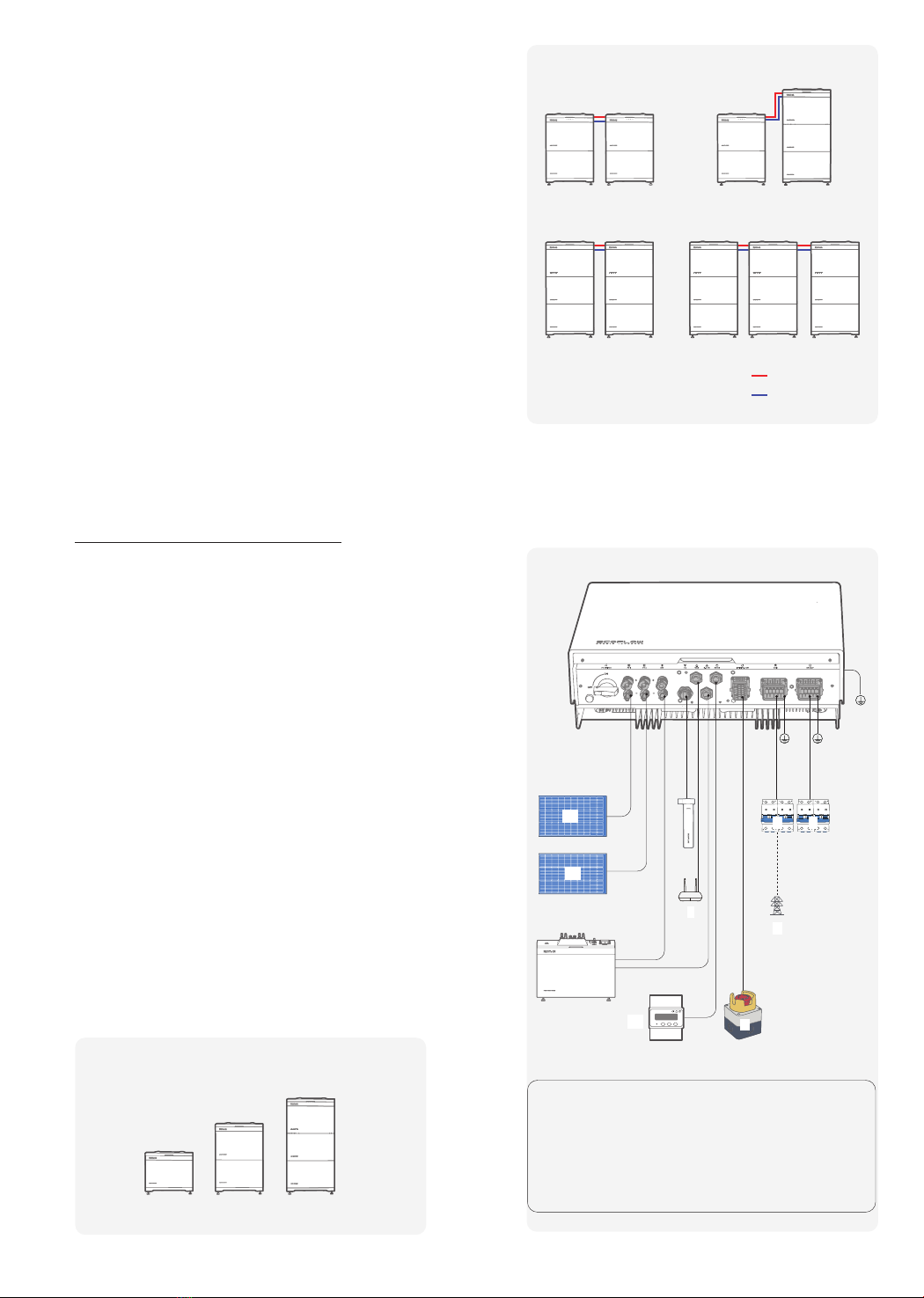
types, ensure that they are at least 30 mm away from each other. Mutual
entanglement or cross-deployment is not allowed.
4. Ensure that the cables used in a grid-tied PV power system are properly
connected and insulated and meet specifications.
1. After system installing and connecting electrical, power on the battery
system in a timely manner to avoid capacity loss or irreversible damage to
the batteries.
2. Correctly set the battery operation management parameters.
3. The customer or a third party is not allowed to use the batteries beyond
the scenarios specified by the Company: such as connecting extra loads
to the battery, or using with other batteries, including but not limited to
batteries of other brands, or batteries of different rated capacities, etc.
4. Battery operating environment or external power parameters MUST meet
environment requirements: such as the actual operating temperature of
the battery meets the specifications; the power grid is stable, etc.) to avoid
damage to the battery.
5. Batteries shall not be frequently over-discharged.
6. Batteries shall be correctly expanded (maximum 45.9 kWh).
7. Batteries shall not fully charged for a long time.
8. Maintain batteries based on the this manual, such as check battery
terminals regularly.
9. Do not use batteries that have exceeded the warranty period.
10. Capacitive discharge: can be reduced to safety voltage within 10 seconds.
BATTERY SAFETY
BASIC REQUIREMENTS
BASIC REQUIREMENTS
BATTERY EMERGENCY MEASURES
DANGER
• Do not expose batteries at high temperatures or around heat-generating
sources. The battery may cause a fire if overheated.
• Do not disassemble, alter, or damage batteries. For example, do not insert
foreign objects into batteries or place batteries in water or other liquids.
• The fire hazard of the battery energy storage system is high. Consider the
following safety risks before handling batteries:
- Battery electrolyte is combustible, toxic, and volatile.
- Battery thermal runaway can generate flammable gas and harmful gas
such as CO and HF.
- The concentration of flammable gas generated from battery thermal
runaway may cause deflagration and explosion.
• Obvious battery abnormalities, such as electrolyte leakage and structural
deformation, indicate potential safety risks. Contact your installer or
professional personnel to remove and replace the battery.
• The batteries must be stored separately inside the packaging. Do not store
batteries together with other materials or in the open air. Do not stack
batteries too high (Allows stacking of up to three packs).
• Do not remove the battery packaging before use.
• Move batteries in the correct direction. Do not place a battery upside down
or tilt it.
• Protect batteries from impact.
• Do not perform welding or grinding work around batteries to prevent fire
caused by electric sparks or arcs.
• Use batteries within the temperature range specified in this manual.
• Do not use damaged batteries (such as damage caused when a battery
is dropped, bumped, or dented on the enclosure). Damaged batteries
may release flammable gases. Do not store damaged batteries near
undamaged products.
• Do not place damaged batteries in close proximity to flammable materials.
Do not approach the damaged batteries unless you are a professional.
• Monitor damaged batteries during storage for signs of smoke, flame,
electrolyte leakage, or heat.
• Do not place irrelevant objects on the top of the equipment or insert them
into any position of the equipment.
• Remove any metal objects from yourself before operating batteries, such
as watches and rings.
• Do not place the battery module in a fire, water or other liquids.
• Do not use water to clean electrical components of the equipment.
• Avoid contact with leaked liquids or gases in the case of battery leakage
or abnormal odor. Do not approach the battery. Contact professionals
immediately. Professionals must wear safety goggles, rubber gloves, gas
masks, and protective clothing.
• Electrolyte is corrosive and can cause irritation and chemical burns. Should
you come into direct contact with the battery electrolyte, do as follows:
- Inhalation: Evacuate contaminated areas, get fresh air immediately, and
seek immediate medical attention.
- Eye contact: Immediately flush your eyes with water for at least 15
minutes, do not rub your eyes, and seek medical attention immediately.
- Skin contact: Wash the affected areas immediately with soap and water
and seek medical attention immediately.
- Ingestion: Seek immediate medical attention.
• If the battery catches fire, extinguish the fire with sand, carbon dioxide, or
dry powder fire extinguishers.
• Do not contact with high-voltage components during fire fighting to
prevent the risk of electric shock.
• If any part of the batteries is submerged in water, do not touch the
batteries to avoid electric shock.
• Do not use batteries that have been soaked in water. Contact a battery
recycling company for disposal.
• If a battery pack is dropped or violently impacted during installation,
internal damage may occur. Do not use such battery packs; otherwise,
safety risks such as cell leakage and electric shock may arise. Contact the
professionals to transfer the battery to an open and safe place, or contact a
recycling company for disposal.
• The operation and service life of the battery depend on the operating
temperature. Install the battery at a temperature equal to the ambient
temperature or in a better environment.
• The operating temperature of the battery ranges from –20°C to +50°C. If
the battery is installed in a cold environment, the built-in thermal control
system starts to heat the battery to achieve better performance. The
heating process consumes rechargeable power, which reduces the system
energy efficiency for a short time in cold weather.
• If the battery is stored in a cold environment (for example, 0°C) before
installation, the battery needs some time (< 30mins) to heat up before
it can be charged. You are advised to place the battery in a warm place
before installation.
• When the ambient temperature of the battery is higher than +45°C or
lower than –10°C, the battery charge and discharge power will be derated.

3
1. When moving the equipment by hand, wear protective gloves to prevent
injuries.
2. When moving the batteries, both hands should hold the handle at the top
of the battery firmly, do not put your hands at the bottom of the battery
when the batteries are being stacked and installed, otherwise, it may crush
your hands.
3. Move the batteries with precaution as the battery modules are heavy.
When two or more people are needed to assist in moving the batteries,
ensure communication and coordination between personnels to prevent
being crushed or sprained.
EQUIPMENT AND PERSONNEL SAFETY
REQUIREMENTS
MOVING THE EQUIPMENT
1. Use wooden or fiberglass ladders when you need to perform live working
at heights.
2. Before using a ladder, check that it is intact and confirm its load bearing
capacity. Do not overload it.
3. Make sure the operator is regulated in the use of installation tools, such as
ladders, electric paddles, drills, etc. Make sure the tool power cord is not
tangled.
4. When installing, strictly prevent screws, nuts and spacers from falling
inside the equipment and ensure that the tools (such as electric drill bit)
do not fall into the gap between the installed equipment and the wall to
prevent delaying the installation.
USING TOOLS
1. Wear goggles and protective gloves when drilling holes.
2. When drilling holes, protect the equipment from shavings or dust. After
drilling, clean up any shavings or dust that have accumulated at the
installation site in a timely manner, otherwise, it may block the drilled hole.
• Battery charge: The junction box connects to the battery terminals (BAT+
and BAT–) of the inverter. Under the control of the inverter, the system
charges the batteries and stores excessive PV energy in batteries.
• Battery discharge: When the PV energy is insufficient to supply power to
the loads, the system controls the batteries to supply power to the loads.
The battery energy is output to the loads through the inverter.
DRILLING HOLES
Product
Introduction
FUNCTION
This battery system consists of a battery junction box, battery expansion
modules and a battery base. It can store and release electric energy based
on the requirements of the inverter management system. The input and
output ports of the EF BD-5.1-S1 battery are high-voltage direct current
(HVDC) ports.
BATTERY CAPACITY DESCRIPTION
NETWORKING APPLICATION
The battery supports power and capacity expansion. Up to three junction
boxes can be connected in parallel. One junction box supports a maximum
of three battery expansion modules.
EcoFlow PowerOcean LFP Battery is a parallel connected high voltage
battery system, compatible with our 3-phase hybrid inverter.
Signal cable
DC Input cable
30.6kWh 45.9kWh
20.4kWh
A. Inverter
B. PV string(sold separately)
C. AC switch (not included)
D. Power grid
E. EF BD-5.1-S1 batteries
F. 4G module (Optional)
G. Smart Meter
H. Emergency Stop Button
(Optional)
I. Router
25.5kWh
A
H
D
C C
B
B
G
F
I
5.1kWh
10.2kWh
15.3kWh
For information on the disposal of electrical and electronic equipment,
please visit the following website:
https://eu.ecoflow.com/pages/electronic-devices-disposal
DISPOSAL
E

4
APPEARANCE
❶Trim cover
❷Battery junction box
❸Battery expansion module
❹Base
❺Adjustable feet
❶Click-on terminal
❷Handles
❸Radiator grille
❹Pressure release valve
❺Click-on terminal
❶Fuse
❷Lock hole button: press and
hold to reveal the lock hole
and lock to prevent accidental
startup.
❸BATTERY SWITCH:Controls
only the battery module, no
control over other power
❹Ground point
❺Battery terminal (BAT-/BAT+)
❻Communication port (COM2/
COM1)
❼BATTERY ON/OFF button
LABEL DESCRIPTION
ENCLOSURE LABELS
EF BD-B-S1
BASE
EF BD-JC-S1
BATTERY JUNCTION BOX
EF BD-5.1-S1
BATTERY
Icon Name Meaning
Electric shock
warning Caution, risk of electric shock
Delayed discharge
Danger to life due to high
voltages in the inverter; observe
a waiting time of 5 minutes.
High voltages that can cause
lethal electric shocks are
present in the live components
of the inverter.
Prior to performing any work on
the inverter, disconnect it from
all voltage sources as described
in this document.
Burn warning
Do not touch a running
equipment because the
enclosure is hot when the
equipment is running.
Refer to
documentation
Reminds operators to refer to
the documents delivered with
the equipment.
Grounding
Indicates the position for
connecting the protective
earthing (PE) cable.
Operation warning
Do not remove the AC/DC
connector when the equipment
is running.
Symbol of a crossed-
out trash can
WEEE designation
Do not dispose of the product
together with the household
waste but in accordance with the
disposal regulations for electronic
waste applicable at the installation
site.
CE marking
The product complies with the
requirements of the applicable
EU directives.
5 mins
Do not
disconnect
under load
❶❷❸ ❹ ❹❺ ❺
❺
❻ ❼
❹❺
❶Click-on terminal
❷Level
❸Adjustable feet mounting holes
❷
❸
The labels are for reference only.
❶
❶
❷
❸
❹
❷
❸
❶

5
FEATURES
• Supports multiple working modes such as grid-tied, power backup
scenario, self-consumption mode.
• Allows users to query the total discharge capacity in the product life cycle
in real time.
• Standard battery DC terminals are used for system connection.
• Modular design is adopted for batteries, which are stacked and connected
without external cables.
• Modular design is adopted for battery junction box, which is designed for
easy connection to the inverter.
• Sleek Design saves installation space.
• The battery system supports power expansion, battery capacity expansion,
and hybrid use of old and new batteries.
• The battery system supports isolation of failed battery modules to ensure
that the energy storage system can still operate normally.
• The factory defaults meet the requirements of target markets and the
battery can be started by pressing only one button and supports black
startup.
• The LED indicator shows the status. You can also use the EcoFlow app to
perform local and remote operations and manage the battery anytime and
anywhere.
• BMS module is embedded within every battery pack, achieving a compact
design with no extra power module on top of batteries.
• Active aerosol fire protection module in every battery pack to secure
maximum safety.
Works with the inverter, supports plug-and-play, and integrates the mo-
bile phone app.
MULTI-SCENARIO AND MULTI-WORKING MODE
EASY INSTALLATION AND REPLACEMENT
FLEXIBLE SCALABILITY
INTELLIGENT OPERATION AND MAINTENANCE
SAFE AND EFFICIENT
INTELLIGENT AND SIMPLE OPERATION
System
Modes
SELF-POWERED MODE
• This mode applies to areas where the electricity price is high, or areas
where the feed-in tariff subsidy is low or unavailable.
• Excess PV energy is stored in batteries. When PV power is insufficient or
no PV power is generated at night, batteries discharge to supply power to
the loads, improving the self-consumption rate of the PV system and the
self-sufficiency rate of residential energy, and reducing electricity costs.
• In this mode, by default, the charge cutoff capacity is 100% and the
discharge cutoff capacity is 5% for EcoFlow EF BD-5.1-S1 LFP batteries.
System
Installation
For System Installation, please refer to Installation Guide delivered with the
equipment.
Checking
before the Installation
Electrical
Connection
For Electrical Connection, please refer to Installation Guide delivered with the
equipment.
Before unpacking the EF BD-5.1-S1, check the outer packing for damage,
such as holes and cracks, and check the EF BD-5.1-S1 model. If any
damage is found , do not unpack the package and contact your dealer as
soon as possible.
After unpacking the EF BD-5.1-S1, check that the deliverables are intact
and complete. If any item is missing or damaged, contact your supplier.
CHECKING OUTER PACKING
CHECKING DELIVERABLES
For details about the number of accessories delivered with the EF BD-
5.1-S1, see What's In The Box in the Installation Guide.
SYSTEM POWER-ON
LED INDICATOR: FOUR BARS
Blinking On
Carousel white
Off
1. Set the BATTERY SWITCH on top of the Junction Box to ON position.
2. Turn on the AC switch between the inverter and the power grid.
3. Set the PV SWITCH at the bottom of the inverter to ON position.
4. Observe the LED to check the inverter operating status.
PROCEDURE (ON-GRID AND PV MODULE CONFIGURED)
1. Set the BATTERY SWITCH on top of the Junction Box to ON position.
2. Turn on the AC switch between the inverter and the power grid.
3. Set the PV SWITCH at the bottom of the inverter to ON position.
4. After commissioning, press and hold for three seconds the BATTERY ON/
OFF button on top of the battery junction box.
5. Observe the LED to check the inverter operating status.
PROCEDURE (OFF-GRID AND NO PV MODULE CONFIGURED)
For System Commissioning, please refer to Installation Guide delivered with
the equipment.
System
Commissioning
Charge Status Description
0-25%
25-50%
50-75%
75-99%
100%
Discharge Status Description
<5%
5-25%
25-50%
50-75%
75-100%
Firmware Upgrading Status Description
Firmware Upgrading is
in progress
Faulty Status Description
Electrical connection is
faulty
Communication is faulty
Battery is faulty
Battery junction box is
faulty

6
The Battery junction box has a built-in DC 1500 V/20A replaceable fuse.
Under normal operating conditions, there is no risk of fuse blowing. When
an external short circuit occurs and the battery management system
is not protected in time, the fuse will blow immediately to protect the
battery. When a short circuit occurs and the battery cannot be charged
or discharged, the fuse must be replaced. Replacement procedure is as
follows:
To ensure that the battery can operate properly for a long term, you are
advised to perform routine maintenance on it as described in this chapter.
System
Maintenance
SYSTEM POWER-OFF
1. Send a shutdown command on the App.
2. Turn off the AC switch between the inverter and the power grid.
3. Set the PV SWITCH at the bottom of the inverter to OFF position.
4. (Optional) Press and hold the button on the PV SWITCH to reveal the lock
hole and lock it up to prevent accidental startup. The lock is prepared by
the customer.
5. Set the BATTERY SWITCH on top of the Junction Box to OFF position.
6. (Optional) Press and hold the button on the BATTERY SWITCH to reveal
the lock hole and lock it up to prevent accidental startup. The lock is
prepared by the customer.
7. Press and hold the BATTERY ON/OFF button of the junction box for 10
seconds, until the indicator is off.
PROCEDURE
BATTERY STORAGE REQUIREMENTS
• Only qualified professionals are allowed to install, operate, and maintain
the equipment.
• Before maintaining the equipment, power it off and follow the instructions
on the delayed discharge label to ensure that the equipment is powered
off.
• (Optional) After setting the BATTERY SWITCH on the top of the battery
junction box to OFF position, it should be locked to prevent accidental
startup.
• Before moving or reconnecting the equipment, disconnect the mains and
batteries and wait for five minutes until the equipment powers off. Before
maintaining the equipment, check that no dangerous voltages remain in
the DC terminals to be maintained by using a multimeter.
• Place temporary warning signs or erect fences to prevent unauthorized
access to the maintenance site.
• If the equipment is faulty, contact your dealer.
• The equipment can be powered on only after all faults are rectified. Failing
to do so may escalate faults or damage the equipment.
• Maintenance personnel must be trained to operate and maintain the
equipment safely and correctly, take comprehensive precautionary
measures, and be equipped with protective instruments.
• When replacing batteries, replace them with batteries or battery strings of
the same type.
• Take out all tools and parts from the equipment after maintenance is
complete.
• When not in use for extended periods, store and recharge batteries
according to this document.
Check Item Check Method Maintenance
Interval
System
cleanliness
Check periodically that the heat
sinks are free from obstacles and
dust.
If there is any stain/dirt, use a dry,
soft cloth to wipe it off and prohibit
the use of stain removing powder,
any liquid, coarse brush, abrasives
or hard objects to clean the
equipment.
Ensure equipment ventilation and
heat dissipation.
Once every 6
months
System running
status
Check that the equipment is not
damaged or deformed.
Check that the equipment operates
with no abnormal sound.
Check that all equipment
parameters are correctly set during
operation.
Once every 6
months
Electrical
connection
Check that cables are secured.
Check that cables are intact.
Once every 6
months
Grounding
reliability
Check that ground cables are
securely connected.
Once every 6
months
Seal ability
Check that unused terminals, ports,
waterproof covers are locked as
delivered.
Once every 6
months
• Place batteries according to the signs on the packing case during storage.
Do not put batteries upside down or sidelong.
• Stack battery packing cases by complying with the stacking requirements
on the external package.
• Handle batteries with caution to avoid damage.
• The storage environment requirements are as follows:
- Ambient temperature: -10–55°C; recommended storage temperature:
20–30°C
- Relative humidity: 0% to 100%
- Place batteries in a dry and clean place with good ventilation.
- Place batteries in a place that is away from corrosive organic solvents
and gases.
- Keep batteries away from direct sunlight, heat source, fire source and
water source.
• The batteries in storage must be disconnected from external devices. The
indicators on the battery junction box should be off.
• If the battery is not used for a long period of time, it is recommended
to be stored intact in a semi-charged state (60% SOC). The battery is
recommended to be discharged to 30% and then recharged to 60% every
three months.
• If the power level of the battery is lower than 1% after use, recharge it
to 60% before storage. If the battery has been idle for a long time when
the power is seriously insufficient, it will cause irreversible damage to the
cells and shorten the service life of the battery.
• If the battery has been idle for a long time and the power level is severely
low, it will enter a deep sleep protection mode. In such a case, recharge the
battery before using it again.
• When solar irradiance declines and the PV string current drops to
below 0.5 A, and the battery SOC is excessively low, the system will
automatically switch to Grid power.
BATTERY STORAGE AND RECHARGE
REPLACING A FUSE
WARNING
WARNING
• Power off the system and follow the instructions on the delayed discharge
label to ensure that the equipment is powered off.
• Wear proper PPE before any operations.
ROUTINE MAINTENANCE
NOTICE
• Please use fuses with local certification standards
1. Power off the system. For details, see chapter: System Power-Off.
PROCEDURE
WARNING
• After the system is powered off, the remaining electricity and heat still
exist in the chassis, which may cause electric shocks or burns. Therefore,
you need to wear protective gloves and perform operations 5 minutes after
the system is powered off.
• Only qualified professionals are allowed to replace a fuse.
2. Loosen the screws on the fuse shell.
3. Lift the fuse box opening, remove the fuse, insert a new fuse of the same
specification as the old one into the slot, and close the fuse box.
4. Lock the fuse shell with screws.
❷
❶

7
❸
FUSE SPECIFICATION
Fuse type Fast blow fuse
Rated voltage 1500 V DC
Rated current 20 A
Breaking capacity 10 kA@1500 Vd.c.
Nominal fusing heat I2T 400-2200
Cold resistance value
Dimensions 14.2*5 mm
Fuse model A842200b00
Used Batteries
Disposal
•When conditions permit, be sure to completely discharge the battery
before placing the battery in the designated battery recycling bin. This
product contains batteries. Batteries are dangerous chemicals and should
not be disposed of in ordinary trash bins. For details, follow the local
battery recycling and disposal laws and regulations.
•If the battery cannot be completely discharged due to battery failure, do
not dispose of the battery directly in the battery recycling bin, and contact
a professional battery recycling company for further processing.
•If the battery cannot start after being discharged, dispose of it according to
local laws and regulations on battery recycling and disposal.
•Hereby, our products have met the regulations of BattG in Germany.

8
Technical
Parameters
Number of battery packs
EF BD-JC-S1 x 1
EF BD-5.1-S1 x 1
EF BD-B-S1 x 1
EF BD-JC-S1 x 1
EF BD-5.1-S1 x 2
EF BD-B-S1 x 1
EF BD-JC-S1 x 1
EF BD-5.1-S1 x 3
EF BD-B-S1 x 1
Performance
Battery module capacity 5.1kWh 10.2kWh 15.3kWh
Max. output power 3.3kW 6.6kW 9.9kW
Max. input power 2.5kW 5kW 7.5kW
Nominal voltage 800V
Operating voltage range 720~960V
Battery cell type LFP
Compliance
CE/CB/TUV MARK
Safety standard IEC/EN62619, IEC/EN62040-1,
IEC/EN62477-1, ISO13849
Delivery standard UN38.3
EMC EN 61000-6-1, EN 61000-6-3
General
specification
Dimension
(without adjustable feet) 680*612*183mm 680*1009*183mm 680*1406*183mm
Power module weight 65.6kg 120.9kg 176.2kg
Installation Floor stand
Operating temperature -20°C~50°C
Max. operating altitude 3000m
Cooling method Natural convection
Noise level
Relative humidity 0~100% RH
Protection level IP65
Protective class I

9
PAP
22
Raccoltacarta
Copyright©2023 Ecoflow All Rights Reserved.
Contact Us:
Ecobat Battery, 36a Vanguard Way,
Battleeld Enterprise Park, Shrewsbury,
Shropshire, SY1 3TG, UK
0333 577 6690
Table of contents
Other EcoFlow Batteries Pack manuals