Production Basics 8654 User manual

Production Basics, Inc. Massachusetts, USA 800.318.2770 617.926.8100 Fax: 617.926.8010 www.pbasics.com
ASSEMBLY MANUAL
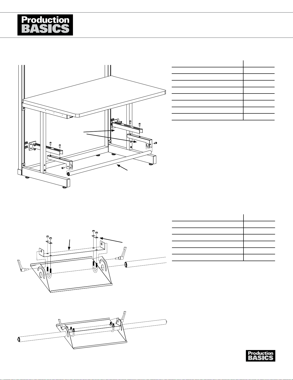
Assemble Footrest Plate Bracket as shown.1.
Slip Footrest Tube through holes in Footrest Plate and2. the U-Bolts.
Secure by inserting the handle into the weld nut on the3. bracket.
To adjust Footrest Plate placement, loosen or tighten4. U-Bolt on underside of plate. To adjust angle, use
handles on the side.
Attach footrest as directed (Adjustable Tube or RTW5. Tube).
Note: Footrest Plate must be installed on Tube•
Footrest before tube is secured into position.
FOOTREST PLATE
Item Number 8668 PARTS AND HARDWARE QUANTITY
Footrest Plate 1
Plate Support 1
U-Bolts 2
Nuts 4
Handles 2
U-Bolt Retainer Plate 2
Plate Support
U-Bolt Retainer Plate
Position tube footrest in 1 of the 3 hole positions on1. lower cross member on each RTW Frame Leg.
Insert Basic Bolt through lower cross member, then in2. footrest. Tighten with Basic Allen Wrench.
PARTS AND HARDWARE QUANTITY
Footrest Tube 1
Basic Bolts 2
Allen Wrench 1
RTW TUBE FOOTREST
Item Numbers 8654
Accessories
1303A865
1
Production Basics, Inc. Massachusetts, USA 800.318.2770 617.926.8100 Fax: 617.926.8010 www.pbasics.com
ASSEMBLY MANUAL
Assemble Footrest Plate Bracket as shown.1.
Slip Footrest Tube through holes in Footrest Plate and2. the U-Bolts.
Secure by inserting the handle into the weld nut on the3. bracket.
To adjust Footrest Plate placement, loosen or tighten4. U-Bolt on underside of plate. To adjust angle, use
handles on the side.
Attach footrest as directed (Adjustable Tube or RTW5. Tube).
Note: Footrest Plate must be installed on Tube•
Footrest before tube is secured into position.
FOOTREST PLATE
Item Number 8668 PARTS AND HARDWARE QUANTITY
Footrest Plate 1
Plate Support 1
U-Bolts 2
Nuts 4
Handles 2
U-Bolt Retainer Plate 2
Plate Support
U-Bolt Retainer Plate
Prepare brackets as shown. Adjust bracket according to1. operator comfort and depth of workstation. Brackets are
LEFT and RIGHT specic.
Attach footrest tube between the bracket assemblies2. using a Basic Bolt.
Insert a Basic Bolt into the mounting plate on the bracket3. assembly and secure with a Basic Nut turning one
revolution. Repeat for other bracket.
Install bracket onto frame under the worksurface.4. Measure or use a level to ensure brackets are at the
same height. Repeat for other bracket.
Note: Adjust bracket position to accommodate•
operator and depth of station.
Accessories
C-LEGADJUSTABLE TUBE FOOTREST
Item Numbers 8664, 8665, 8666, 8667
Bracket
Footrest Tube
Left
PARTS AND HARDWARE QUANTITY
Footrest Tube 1
Brackets (2 pieces each) 2
Basic Bolts 10
Basic Nuts 4
Allen Wrench 1
Other Items Needed (not included)
Tape Measure
Level
1303A866
1
This manual suits for next models
5
Popular Industrial Equipment manuals by other brands

SUHNER
SUHNER ROTOmaster 12, ROTOmaster 15 Technical document

Spraying Systems
Spraying Systems AutoJet ES250 owner's manual

Harmonic Drive
Harmonic Drive SHG Series manual

KEBCO
KEBCO COMBIVERT S6 Series Instructions for use

KEPCO
KEPCO PROTROL Installation & operating instructions

DOUGHXPRESS
DOUGHXPRESS DXP-CRS owner's manual

AutomationDirect
AutomationDirect CLICK PLUS C2-01CPU Series quick start guide

Let's Go Aero
Let's Go Aero GearDeck H00604 product manual

KEBCO
KEBCO COMBINORM B Instructions for use

Harmonic Drive
Harmonic Drive PMG-S Series Assembly and service manual

SPX FLOW
SPX FLOW Votator II instruction manual

Tolomatic
Tolomatic MXP16N instructions


