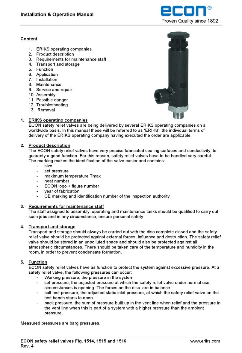
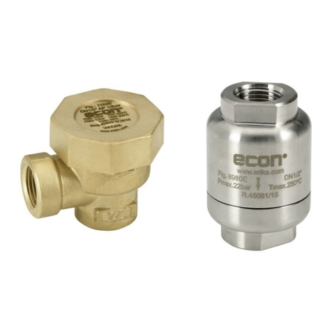
Econ Fig. 517 User manual

Installation & Operation Manual
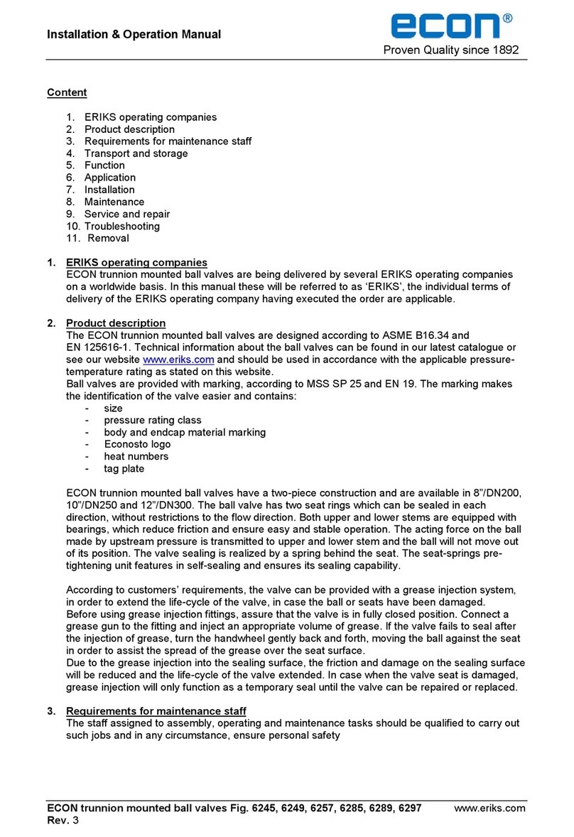
Proven Quality since 1892
ECON safety valves Fig. 512, 517 and 518 www.eriks.com
Rev. 1
Content
1. ERIKS operating companies
2. Product description
3. Requirements for maintenance staff
4. Transport and storage
5. Function
6. Application
7. Installation
8. Maintenance
9. Service and repair
10. Possible danger
11. Troubleshooting
12. Removal
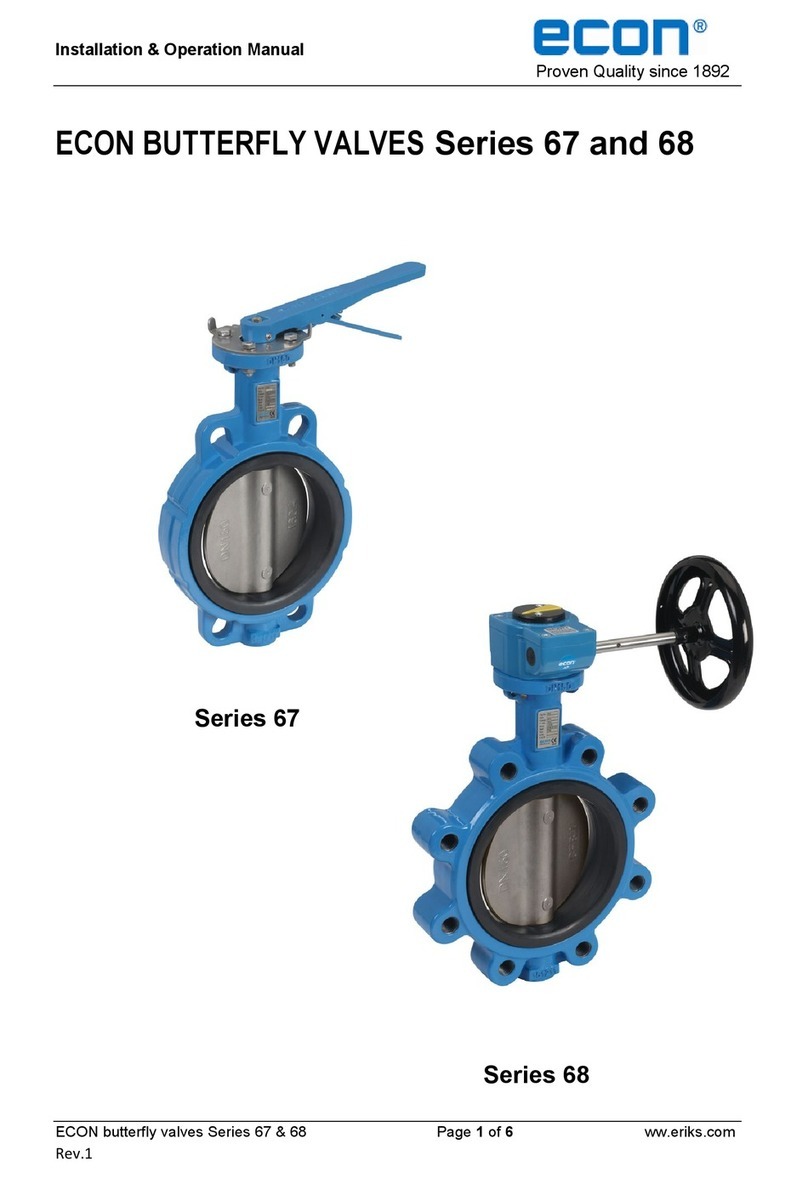
Fig. 512 Fig. 517 Fig. 518
1. ERIKS operating companies
ECON safety valves are being delivered by several ERIKS operating companies on a worldwide
basis. In this manual these will be referred to as ‘ERIKS’, the individual terms of delivery of the
ERIKS operating company having executed the order are applicable.
2. Product description
The ECON safety valves fig 512 / 517 / 518 are type-tested acc ISO 4126-1. They are approved
PED category IV (module B+D).
Information about the safety valves can be found in the according datasheet and capacity table.
The safety valves may only be used in accordance with the applicable pressure-temperaturerating
as stated in its datasheet.
The marking makes the identification of the valve easier and contains:
- ECON logo + figure number
- size
- CE marking and identification number of the inspection authority
- flow area
- sealing material
- serial number
- heat number
- set pressure

Installation & Operation Manual
Proven Quality since 1892
ECON safety valves Fig. 512, 517 and 518 www.eriks.com
Rev. 1
3. Requirements for maintenance staff
The staff assigned to assembly, operating and maintenance tasks should be qualified to carry out
such jobs and in any circumstance, ensure personal safety.
4. Transport and storage
The safety valves have very precise fabricated sealing surfaces in order to avoid leakage. During
transport and installation, they have to be handled very careful to avoid any damage on these
sealing surfaces
Transport and storage should always be carried out with the disc complete closed and the safety
valve should be protected against external forces, influence and destruction. The safety valve
should be stored in an unpolluted space and should also be protected against all atmospheric
circumstances. There should be taken care of the temperature and humidity in the room, in order
to prevent condensate formation.
5. Function
ECON safety valves have the function to protect the system against excessive pressure. When
normal pressure conditions are achieved, the valve will re-close automatically.
At a safety valve, the following pressures can occur:
- working pressure: the pressure in the system at normal working condition
- set pressure: the adjusted pressure at which the safety valve under normal use
circumstances commences to open. The forces on the disc are in balance.
- cold differential test pressure (CDTP): the adjusted static inlet pressure, at which the safety
valve on the test bench starts to open.
- back pressure: the sum of built-up pressure (pressure at the outlet of a safety valve caused
by flow through the valve and the discharge system) and superimposed back pressure
(existing pressure in the discharge system at the moment the safety valve is still closed)
Back pressure will influence the behavior and capacity of the safety valve and must be taken
into account when selecting a safety valve.
6. Application
ECON safety valves with threaded connection are mainly applied in the process industry and are
suitable for gasses and liquids. This type of safety valve is also suitable as an overflow. For the
use of extreme conditions e.g. aggressive or abrasive media, it is recommended to mention this at
the ordering stage, to verify whether the valve is suitable.
The installation designer is responsible for the safety valve selection, suitable for the working
conditions. The valves are unsuitable, without written permission of an ERIKS company, to apply
for hazardous media as referred into Regulation (EC) No 1272/2008.
Fig.512: Safety valve with gas-tight cap
DN
do
L
h
H
SW
Weight
G ["]
[mm]
[kg]
½
13
30
30
71
28
0,4
¾
19
33
35
79
34
0,6
1
25
40
41
95
41
1
1 ¼
30
45
45
110
52
1,75
1 ½
38
50
51
135
58
2,3
2
50
60
60
140
70
3,3

Installation & Operation Manual
Proven Quality since 1892
ECON safety valves Fig. 512, 517 and 518 www.eriks.com
Rev. 1
Fig.517: Safety valve with non-gastight cap
Fig.518: Safety valve with lifting lever and non-gastight cap
DN
do
L
h
H
SW
Gewicht
G ["]
[mm]
[kg]
½
13
30
30
62
28
0,4
¾
19
33
35
73
34
0,6
1
25
40
41
90
41
1
1 ¼
30
45
45
110
52
1,6
1 ½
38
50
51
130
58
2,2
2
50
60
60
135
70
3,1
DN
do
L
h
H
SW
Gewicht
G ["]
[mm]
[kg]
½
13
30
30
89
28
0,5
¾
19
33
35
101
34
0,7
1
25
40
41
119
41
1
1 ¼
30
45
45
140
52
2
1 ½
38
50
51
166
58
2,6
2
50
60
60
172
70
3,6

Installation & Operation Manual
Proven Quality since 1892
ECON safety valves Fig. 512, 517 and 518 www.eriks.com
Rev. 1
7. Installation
During the assembly of the ECON safety valves, the following rules should be observed:
- make sure before an assembly that the safety valves were not damaged during the transport
or storage.
- make sure that the applied safety valves are suitable for the working conditions, medium used
in the plant and the right system connections, according to pressure and temperature limits as
per the tag plate.
- the interior of the safety valve and pipeline must be free from foreign particles.
- before plant startup, especially after repairs carried out, flash out the pipeline, before installing
the safety valves.
- safety valves have to be installed with the spring bonnet vertically upward
- the body part which contains the spring and the adjusting spring, may not be insulated;
otherwise the spring gets to warm.
- the inlet line should be as short as possible; pressure drop in inlet line must be regarded (fi
regarding ISO 4126-9)
- an outlet line can be mounted at the outlet of the safety valve in order to discharge the
medium to a safe location. For liquids the outlet line should be sloped so the liquid is drained
by gravity . Gases and vapors can be evacuated by a rising outlet line.
- Outlet line must be sized in order to restrict the built-up back-pressure (maximum allowed
built-up back pressure: 15% of set pressure).
- when used with steam or other condensable gases, the outlet line must be executed with a
condensate drain
- it is not allowed to use isolating valves in the in- and/or outlet line. In case isolation of a safety
valve is wanted, only specific solutions are allowed, for instance a change-over-valve for
safety valves.
- excessive vibrations, damaging transverse, bending and tensional forces on inlet/outlet line
and on the safety valve itself must be avoided.
- bolted joints on the pipeline must not cause additional stress resulted from excessive
tightening; the user shall select proper bolts and gaskets according the working temperature,
working pressure and medium.
8. Maintenance
Before starting any service jobs, make sure that the medium supply to the pipeline is cut off,
pressure was decreased to ambient pressure, the pipeline is completely cleaned and ventilated
and the plant is cooled down. Always keep safety instructions in mind and take all personal safety
precautions.
During maintenance, the following rules should be observed:
- always keep personal safety precautions in mind and always use appropriate protection
e.g. clothing, masks, gloves etc.
- be alert that the temperature still can be very high or low and can cause burns.
- check the safety valve on all possible leaking possibilities.
- check if all bolts and nuts are still fastened.
- After installation, the safety valve should be checked and maintained periodically at least
every 3 months, depending on the medium.
-
The safety valves can’t be operated, because they are working on the force executed by the
medium pressure.
If testing is necessary according international and/or national regulations for the concerned
installation (for instance steam), the safety must be executed with a lifting device, like lever or
lifting knob.
For safety valves with lifting device, manual operation is possible at operating pressure ≥ 85% of
the set pressure. Manual operation can be done to test the safety valve or when leakage is
detected at the outlet of the safety valve.

Installation & Operation Manual
Proven Quality since 1892
ECON safety valves Fig. 512, 517 and 518 www.eriks.com
Rev. 1
9. Service and repair
All service and repair jobs should be carried out by authorized staff, using suitable tools and user
shall use valve parts, bolt and nut of the same size and material as the original one.
- all service and repair jobs should be carried out by authorized staff, using suitable tools
- only original valve parts may be used
- weld repair and drilling of the valve is forbidden.
- it is forbidden to replace the bolt, nut or packing when the valve is under pressure.
- after replacement, service or blow-off pressure adjustment, it is necessary to check the
safety valve on good functioning and tightness of all connections.
- service and/or repair on the safety valve may only be executed by approved workshops.
After repair, the safety valve must be set and sealed again!
- any warranty expires as soon as the seal has been removed.
10. Possible dangers
Leakage can cause danger of the safety and health of persons, animals and goods. Even when
the safety valve is functioning well, there can occur dangers which one must take into account.
Following dangers can occur:
- an over-pressure in the system is possible if the safety has not been sized according the
correct process data. Also the execution must correspond to the application.
- an over-pressure in the system is possible when the valve is blocked. This can be caused by
the formation of frost on the disc. Eventually, the valve must be protected against freezing.
Freezing can also be caused by expanding gasses at blow-off.
A blocked safety valve can also be caused by sticky media or crystallization; eventually other
safety devices (like bursting discs) can be used.
- when the safety valve blows off, hazardous, cold or hot medium can escape. The medium
must be discharged into a safe area
- injury by hot, cold or sharp parts. This can be avoided, by shielding or insulation.
- a dangerous noise level, when the medium blows off.
- chemical burns, injury or poisoning because of medium left behind in the valve. This can be
avoid by flushing the installation, before assembly.
11. Troubleshooting
It is essential that the safety regulations are observed when identifying the fault.
Problem
Possible cause
Corrective measures
Safety valve doesn’t work
The safety valve is wrong
calculated, for example the
blow-off pressure is wrong
New calculation and adjustment
of the safety valve is necessary
The safety valve is cracked
because of overload
Replace the safety valve, new
calculation and adjustment of
the safety valve is necessary
Piping system clogged
Check piping system
Leakage across valve seat
Disc not properly closed
Check disc opening function
Seat damaged by foreign
particles
Replace the valve
Medium contaminated
Clean the valve and install a dirt
screen
Leakage at the connection
Thread connection not right
Check the connection

Installation & Operation Manual
Proven Quality since 1892
ECON safety valves Fig. 512, 517 and 518 www.eriks.com
Rev. 1
12. Removal
All dismantled and rejected valves cannot be disposed with household waste. The valves are
made of materials which can be re-used and should be delivered to designated recycling centers.
General warning:
General note for products which may be used for seawater:
Although our products can be used in seawater systems it should always be noted that, in case of
installation in a piping system made of materials which are frequently used because of their excellent
seawater resistance (e.g. Cunifer), large potential differences may occur possibly causing corrosion
which could permanently damage the proper functioning and integrity of our product.
A combination of different materials should always be mentioned prior to the purchase of our products
in order for us to give the best possible advice on a safe functioning.
This manual suits for next models
2
Table of contents
Other Econ Control Unit manuals
Popular Control Unit manuals by other brands

Hattersley
Hattersley Fig.1051 Installation and operating instructions
Navim Group Company
Navim Group Company EsiWelma Sensigas UCE1 installation instructions

Telegesis
Telegesis ETRX2-PA product manual
CDVI
CDVI CA-A470-A instructions
Enerpac
Enerpac MHV-1 manual
Siko
Siko MS02 Translation of the original installation instructions
