Siko MS02 User manual

MS02
Deutsch
MS02 · Datum 03.09.2019 · Art. Nr. 82405 · Änd. Stand 172/19
2
Inhaltsverzeichnis
1 Dokumentation . . . . . . . . . . . . . . . . . . . . 3
2 Sicherheitshinweise . . . . . . . . . . . . . . . . . . 3
2.1 Bestimmungsgemäße Verwendung . . . . . . . . . . . 3
2.2 Kennzeichnung von Gefahren und Hinweisen . . . . . . 4
2.3 Zielgruppe . . . . . . . . . . . . . . . . . . . . 4
2.4 Grundlegende Sicherheitshinweise . . . . . . . . . . . 5
3 Identifikation . . . . . . . . . . . . . . . . . . . . . 5
4 Installation . . . . . . . . . . . . . . . . . . . . . . 5
4.1 Mechanische Montage . . . . . . . . . . . . . . . . 5
4.2 Elektrische Installation . . . . . . . . . . . . . . . 6
5 Transport, Lagerung, Wartung und Entsorgung . . . . . . . 8
6 Technische Daten . . . . . . . . . . . . . . . . . . . 9

MS02
Dokumentation Deutsch
MS02 · Datum 03.09.2019 · Art. Nr. 82405 · Änd. Stand 172/19
3
1 Dokumentation
Zu diesem Produkt gibt es folgende Dokumente:
• Datenblatt beschreibt die technischen Daten, die Abmaße, die
Anschlussbelegungen, das Zubehör und den Bestellschlüssel.
• Montageanleitung beschreibt die mechanische und die elektrische
Montage mit allen sicherheitsrelevanten Bedingungen und den dazu-
gehörigen technischen Vorgaben.
Diese Dokumente sind auch unter "http://www.siko-global.com/p/
ms02" zu finden.
2 Sicherheitshinweise
2.1 Bestimmungsgemäße Verwendung
Die Motorsteuerung MS02 ermöglicht die einfache Ansteuerung von
Gleichstrommotoren. Verschiedene Eingangsschaltungsvarianten erlau-
ben den Einsatz an unterschiedliche Positioniersteuerungen. Es kann zwi-
schen reinen Digitaleingängen, unipolarem Analogeingang und bipola-
rem Analogeingang gewählt werden. Die Digitaleingänge wählen Rechts-
bzw. Linkslauf. Der dritte Eingang ermöglicht den Wechsel von Eil- auf
Schleichgeschwindigkeit. Eil- und Schleichgeschwindigkeit lassen sich
getrennt durch zwei Potentiometer zwischen 0 ... 100% einstellen. Der
unipolare Analogeingang bestimmt durch seinen Spannungswert die
Geschwindigkeit. Zwei digitale "Enable" und "Rechts/Links" -Eingänge
dienen zur Freigabe bzw. Richungswahl der MS02. Der bidirektionale Ana-
logeingang bestimmt ebenfalls durch den Spannungswert die Geschwin-
digkeit. Die Polariät gibt die Richtung vor. Der digitale "Enable"-Eingang
dient zur Freigabe.
1. Beachten Sie alle Sicherheitshinweise in dieser Anleitung.
2. Eigenmächtige Umbauten und Veränderungen an der Motorsteuerung
sind verboten.
3. Die vorgeschriebenen Betriebs- und Installationsbedingungen sind
einzuhalten.
4. Die Motorsteuerung darf nur innerhalb der technischen Daten und der
angegebenen Grenzen betrieben werden (siehe Kapitel 6).

MS02
Sicherheitshinweise Deutsch
MS02 · Datum 03.09.2019 · Art. Nr. 82405 · Änd. Stand 172/19
4
2.2 Kennzeichnung von Gefahren und Hinweisen
Sicherheitshinweise bestehen aus dem Signalzeichen und einem Signal-
wort.
Gefahrenklassen
Unmittelbare Gefährdungen, die zu schweren irreversiblen Körperverlet-
zungen mit Todesfolge, Sachschäden oder ungeplanten Gerätereaktionen
führen können, sofern Sie die gegebenen Anweisungen missachten.
Gefährdungen, die zu schweren Körperverletzungen, Sachschäden oder
ungeplanten Gerätereaktionen führen können, sofern Sie die gegebenen
Anweisungen missachten.
Gefährdungen, die zu leichten Verletzungen, Sachschäden oder ungeplan-
ten Gerätereaktionen führen können, sofern Sie die gegebenen Anweisun-
gen missachten.
Wichtige Betriebshinweise, die die Bedienung erleichtern oder die bei
Nichtbeachtung zu ungeplanten Gerätereaktionen führen können und
somit möglicherweise zu Sachschäden führen können.
Signalzeichen
2.3 Zielgruppe
Montageanleitung wendet sich an das Projektierungs-, Inbetriebnahme-
und Montagepersonal von Anlagen- oder Maschinenherstellern, das
über besondere Kenntnisse innerhalb der Antriebstechnik verfügt. Die-
ser Personenkreis benötigt fundierte Kenntnisse über die notwendigen
Anschlüsse einer Motorsteuerung und deren Integration in die komplette
Maschinenanlage.
Nicht ausreichend qualifiziertes Personal
Personenschäden, schwere Schäden an Maschine und Motorsteuerung wer-
den durch nicht ausreichend qualifiziertes Personal verursacht.
`Projektierung, Inbetriebnahme, Montage und Wartung nur durch
geschultes Fachpersonal.
`Dieses Personal muss in der Lage sein, Gefahren, welche durch die
mechanische, elektrische oder elektronische Ausrüstung verursacht
werden können, zu erkennen.
GEFAHR
WARNUNG
VORSICHT
ACHTUNG
WARNUNG

MS02
Identifikation Deutsch
MS02 · Datum 03.09.2019 · Art. Nr. 82405 · Änd. Stand 172/19
5
Qualifiziertes Personal
sind Personen, die
• als Projektierungspersonal mit den Sicherheitsrichtlinien der Elektro-
und Automatisierungstechnik vertraut sind;
• als Inbetriebnahme- und Monatagepersonal berechtigt sind, Strom-
kreise und Geräte/Systeme gemäß den Standards der Sicherheitstech-
nik in Betrieb zu nehmen, zu erden und zu kennzeichnen.
2.4 Grundlegende Sicherheitshinweise
Explosionsgefahr
`Motorsteuerung nicht in explosionsgefährdeten Zonen einsetzen.
3 Identifikation
Das Typenschild zeigt den Gerätetyp mit Variantennummer. Die Lieferpa-
piere ordnen jeder Variantennummer eine detaillierte Bestellbezeichnung
zu.
z. B. MS02-0023
Varianten-Nr.
Geräte-Typ
4 Installation
4.1 Mechanische Montage
Ausfall Motorsteuerung
`Schläge auf das Gerät vermeiden.
`Funkmodul nicht selbst önen.
`Keinerlei Veränderung am Gerät vornehmen.
Das MS02 ist zum Anbau an eine Hutschiene z. B. nach DIN EN 50022, DIN
EN 50035 vorgesehen.
1. Gerät in die Schiene 1einhängen und aufschnappen.
2. Zum Lösen des MS02 mit einem Schraubendreher 2unten einhaken
und in Pfeilrichtung Klemmung lösen.
GEFAHR
VORSICHT

MS02
Installation Deutsch
MS02 · Datum 03.09.2019 · Art. Nr. 82405 · Änd. Stand 172/19
6
1Schiene
2Schraubendreher
Abb. 1: Einbau / Ausbau
1
2
4.2 Elektrische Installation
Zerstörung von Anlagenteilen und Verlust der Steuerungskontrolle
`Alle Leitungen für die Motorsteuerung müssen geschirmt sein.
`Elektrische Verbindungen nicht unter Spannung anschließen oder
lösen.
`Verdrahtungsarbeiten spannungslos durchführen.
`Litzen mit geeigneten Aderendhülsen versehen.
`Vor dem Einschalten sind alle Leitungsanschlüsse und Steckverbindun-
gen zu überprüfen.
`Betriebsspannung gemeinsam mit der Folgeelektronik (z. B. Steue-
rung) einschalten.
Alle Anschlüsse sind prinzipiell gegen äußere Störeinflüsse geschützt. Der
Einsatzort ist so zu wählen, dass induktive oder kapazitive Störungen nicht
auf die Motorsteuerung oder dessen Anschlussleitungen einwirken kön-
nen. Das System in möglichst großem Abstand von Leitungen einbauen,
die mit Störungen belastet sind. Gegebenenfalls sind zusätzliche Maßnah-
men, wie Schirmbleche oder metallisierte Gehäuse vorzusehen. Schütz-
spulen müssen mit Funkenlöschgliedern beschaltet sein.
Zulässige Leistungsaufnahme
Die Versorgung für die Motorsteuerung ist ausreichend zu dimensionieren.
Die Spannungswerte sind abhängig von der Geräteausführung und sind
den technischen Daten in Kapitel 6zu entnehmen.
WARNUNG
ACHTUNG
ACHTUNG

MS02
Installation Deutsch
MS02 · Datum 03.09.2019 · Art. Nr. 82405 · Änd. Stand 172/19
7
Anschlussbelegung
1nur bei Digital
Abb. 2: Belegung
1
2 3 P2
7 8
P11
{
1211109
654
PIN Digital Analog unipolar Analog bipolar
1 Rechtslauf Masse Enable Masse Enable Masse
2 Rechtslauf Plus Enable Plus Enable Plus
3 Linkslauf Masse Rechts/Links Masse nc
4 Linkslauf Plus Rechts/Links Plus nc
5 Eil/Schleich Masse Analog Masse Analog Masse
6 Eil/Schleich Plus Analog 0 ... 10V Analog -10 ... 10V
PIN Belegung Beschreibung
7 PE Schirm Motorleitung
8 PE
9 +UB Spannungsversorgung 24VDC ±20%
10 GND
11 M1 Motoranschluss; vertauschen um die Drehrichtung
zu wechseln
12 M2
Litzenquerschnitt Leitungen 0.14 ... 0.5mm².
Litzenquerschnitt Leitungen Versorgung/Motor (Pin 1 ... 4) 0.75 ...
2.5mm². Das Anschlusskabel zum Motor muss abgeschirmt sein und der
Schirm ist an PE aufzulegen.

MS02
Transport, Lagerung, Wartung und Entsorgung Deutsch
MS02 · Datum 03.09.2019 · Art. Nr. 82405 · Änd. Stand 172/19
8
Nur bei Digitaleingängen
Potentiometer Beschreibung
P1 Einstellung der Geschwindigkeit im Schnellgang; PWM
stufenlos 0 ... 100% (linker Anschlag 0%; rechter
Anschlag 100%). Eingang schnell/ langsam aktiv.
P2 Einstellung der Geschwindigkeit im Schleichgang; PWM
stufenlos 0 ... 100% (linker Anschlag 0%; rechter
Anschlag 100%). Eingang schnell/ langsam aktiv.
Abb. 3: Eingangsschaltung Digitaleingänge
Rechtslauf Plus
Linkslauf Plus
Eil/Schleich Plus
Rechtslauf Masse
Linkslauf Masse
Eil/Schleich Masse
5 Transport, Lagerung, Wartung und Entsorgung
Transport und Lagerung
Motorsteuerung sorgfältig behandeln, transportieren und lagern. Hierzu
sind folgende Punkte zu beachten:
• Motorsteuerung in der ungeöneten Originalverpackung transportie-
ren und/oder lagern.
• Motorsteuerung vor schädlichen physikalischen Einflüssen wie Staub,
Hitze und Feuchtigkeit schützen.
• Anschlüsse weder durch mechanische noch durch thermische Einflüsse
beschädigen.
• Vor Montage ist die Motorsteuerung auf Transportschäden zu untersu-
chen. Beschädigte Motorsteuerungen nicht einbauen.
Wartung
Bei korrektem Einbau nach Kapitel 4ist die Motorsteuerung wartungsfrei.

MS02
Technische Daten Deutsch
MS02 · Datum 03.09.2019 · Art. Nr. 82405 · Änd. Stand 172/19
9
Entsorgung
Die elektronischen Bauteile der Motorsteuerung enthalten umweltschä-
digende Stoe und sind zugleich Wertstoträger. Die Motorsteuerung
muss deshalb nach seiner endgültigen Stilllegung einem Recycling zuge-
führt werden. Die Umweltrichtlinien des jeweiligen Landes müssen hierzu
beachtet werden.
6 Technische Daten
Elektrische Daten Ergänzung
Betriebsspannung 24VDC ±20% (geregelt) mit LED-Indikator, verpolsicher
Motorstrom 3/5/6A (≤12A Peak) Überstromschutz mit Multifuse
Eingänge digital mit LED-Indikator /
analog
Eingänge analog 0 … 10V Impedanz >1.3MΩ
-10 … 10V Impedanz >1.3MΩ
Eingänge digital 15 … 30V, typisch 10mA
Statusanzeige Überstromschutz, Eingangs-
zustand, Betriebsspannung
PWM (Pulsweitenmodula-
tion) Ausgang
~16Hz , stufenlos, 0 …
100%
Softanlauf
Umgebungsbedingungen Ergänzung
Umgebungstemperatur 0 … 50°C
relative Luftfeuchtigkeit ≤95% Betauung nicht zulässig

MS02
English
MS02 · Date 03.09.2019 · Art. No. 82405 · Mod. status 172/19
10
Table of contents
1 Documentation . . . . . . . . . . . . . . . . . . . 11
2 Safety information . . . . . . . . . . . . . . . . . . 11
2.1 Intended use . . . . . . . . . . . . . . . . . . . 11
2.2 Identification of dangers and notes . . . . . . . . . 11
2.3 Target group . . . . . . . . . . . . . . . . . . . 12
2.4 Basic safety information . . . . . . . . . . . . . . 12
3 Identification . . . . . . . . . . . . . . . . . . . . 13
4 Installation . . . . . . . . . . . . . . . . . . . . . 13
4.1 Mechanical mounting . . . . . . . . . . . . . . . 13
4.2 Electrical installation . . . . . . . . . . . . . . . 14
5 Transport, Storage, Maintenance and Disposal . . . . . . 16
6 Technical data . . . . . . . . . . . . . . . . . . . . 16

MS02
Documentation English
MS02 · Date 03.09.2019 · Art. No. 82405 · Mod. status 172/19
11
1 Documentation
The following documents describe this product:
• The data sheet describes the technical data, the dimensions, the pin
assignments, the accessories and the order key.
• The mounting instructions describe the mechanical and electrical
installation including all safety-relevant requirements and the associ-
ated technical specifications.
These documents can also be downloaded at "http://www.siko-global.
com/p/ms02".
2 Safety information
2.1 Intended use
Motor control MS02 allows easy activation of DC-motors. Due to various
types of input circuits MS02 can be combined with dierent kinds of posi-
tion controllers. customers can choose between digital inputs, unipolar
analogue input and bi-polar analogue input. The digital inputs are used to
determine right-hand/left-hand motion. The third input is used for switch-
ing from fast to creep motion. Speed of fast/creep motions are set indi-
vidually via two potentiometers (between 0 ... 100%). Speed is defined
via the voltage value of the unipolar analogue input. Two digital "enable"
and "right/left"-inputs are used for releasing MS02 and for selecting
direction. Also the bi-directional analogue input defines speed viea its
voltage value. Polarity determines direction and the digital "enable"-
input is used to release MS02.
1. Observe all safety instructions contained herein.
2. Arbitrary modifications and changes to this motor control are forbid-
den.
3. Observe the prescribed operating and installation conditions.
4. Operate the motor control exclusively within the scope of technical
data and the specified limits (see chapter 6).
2.2 Identification of dangers and notes
Safety notes consist of the signal symbol and a signal word.
Danger classes
Immediate danger that may cause irreversible bodily harm resulting in
death, property damage or unplanned device reactions if you disregard
DANGER

MS02
Safety information English
MS02 · Date 03.09.2019 · Art. No. 82405 · Mod. status 172/19
12
the instructions given.
Danger that may cause serious bodily harm, property damage or
unplanned device reactions if you disregard the instructions given.
Danger that may cause minor injury, property damage or unplanned device
reactions if you disregard the instructions given.
Important operating information that may facilitate operation or many
cause unplanned device reactions if disregarded including possible prop-
erty damage.
Signal symbols
2.3 Target group
Installation instruction is intended for the configuration, commissioning
and mounting personnel of plant or machine manufacturers who possess
special expertise in drive technology. This group of operators needs pro-
found knowledge of an motor control necessary connections and its inte-
gration into a complete machinery.
Insuciently qualified personnel
Insuciently qualified personnel cause personal injury, serious damage to
machinery or motor control.
`Configuration, commissioning, mounting and maintenance by trained
expert personnel only.
`This personnel must be able to recognize dangers that might arise
from mechanical, electrical or electronic equipment.
Qualified personnel are persons who
• are familiar with the safety guidelines of the electrical and automation
technologies when performing configuration tasks;
• are authorized to commission, earth and label circuits and devices/
systems in accordance with the safety standards.
2.4 Basic safety information
Danger of explosion
`Do not use the motor control in explosive zones.
WARNING
CAUTION
NOTICE
WARNING
DANGER

MS02
Identification English
MS02 · Date 03.09.2019 · Art. No. 82405 · Mod. status 172/19
13
3 Identification
Please check the particular type of unit and type number from the identifi-
cation plate. Type number and the corresponding version are indicated in
the delivery documentation.
e. g. MS02-0023
variant number
type of unit
4 Installation
4.1 Mechanical mounting
Motor control module failure
`Avoid impact on the device.
`Do not open the module yourself.
`Do not modify the device in any way.
The MS02 is intended for mounting on a top-hat rail, e. g. acc. to DIN EN
50022, DIN EN 50035.
1. Hang the device onto the reil 1and snap on.
2. For detaching the MS02, hook in a screwdriver 2below and losen the
clamping in the direction of the arrow.
1reil
2screwdriver
Fig. 1: Installation/ removal
1
2
CAUTION

MS02
Installation English
MS02 · Date 03.09.2019 · Art. No. 82405 · Mod. status 172/19
14
4.2 Electrical installation
Destruction of parts of equipment and loss of regulation control
`All lines for connecting the motor control must be shielded.
`Never wire or disconnect electrical connections while they are live.
`Perform wiring work in the de-energized state only.
`Use strands with suitable ferrules.
`Check all lines and plug connections before switching on the device.
`Switch on operating voltage together with the downstream electronic
unit (e. g., control unit).
Basically, all connections are protected against external interference.
Choose a place of operation that excludes inductive or capacitive interfer-
ence influences on the motor control. When mounting the system keep a
maximum possible distance from lines loaded with interference. If neces-
sary, provide additional installations including screening shields or met-
allized housings. Contactor coils must be linked with spark suppression.
Admissible power input
Supply for the motor control shall be sized suciently. The voltage values
are a function of the device design and can be referred to in the technical
data in chapter 6.
Pin assignment
1only with digital inputs
Fig. 2: Connection
1
2 3 P2
7 8
P11
{
1211109
654
WARNING
NOTICE
NOTICE

MS02
Installation English
MS02 · Date 03.09.2019 · Art. No. 82405 · Mod. status 172/19
15
PIN Digital Analogue unipolar Analogue bipolar
1 right motion ground enable ground enable ground
2 right motion plus enable plus enable plus
3 left motion ground right/Left ground nc
4 left motion plus right/Left plus nc
5 fast/creep motion
ground
analogue ground analogue ground
6 fast/creep motion
plus
analogue 0 ... 10V analogue -10 ... 10V
PIN Designation Description
7 PE screen motor line
8 PE
9 +UB Power supply 24VDC ±20%
10 GND
11 M1 Motor connection; exchange, to change to the
other direction of rotation
12 M2
Strand cross sections of lines 0.14 ... 0.5mm².
Strand cross sections of lines supply voltage/motor (Pin 1 ... 4) 0.75 ...
2.5mm². The connection cable to the motor must be shielded and put the
screen on PE.
Only with digital inputs
Potentiometer Description
P1 Speed setting in fast motion; PWM continously adjust-
able 0 ... 100% (seft stop 0%; right stop 100%).
Active fast/ slow input.
P2 Speed setting in creep motion; PWM continuously
adjustable 0 ... 100% (left stop 0%; right stop 100%).
Inactive fast/ slow input.
Fig. 3: Input circuit/ digital inputs
right motion plus
left motion plus
fast/creep motion plus
right motion ground
left motion ground
fast/creep motion ground

MS02
Transport, Storage, Maintenance and Disposal English
MS02 · Date 03.09.2019 · Art. No. 82405 · Mod. status 172/19
16
5 Transport, Storage, Maintenance and Disposal
Transport and storage
Handle, transport and store motor control with care. Pay attention to the
following points:
• Transport and / or store motor control in the unopened original pack-
aging.
• Protect motor control from harmful physical influences including dust,
heat and humidity.
• Do not damage connections through mechanical or thermal impact.
• Prior to installation inspect the motor control for transport damages.
Do not install damaged motor control.
Maintenance
With correct installation according to chapter 4the motor control requires
no maintenance.
Disposal
The motor control electronic components contain materials that are harm-
ful for the environment and are carriers of recyclable materials at the
same time. Therefore, the motor control must be recycled after it has been
taken out of operation ultimately. Observe the environment protection
guidelines of your country.
6 Technical data
Electrical data Additional information
Operating voltage 24VDC ±20% (controlled) with LED indicator, reverse polar-
ity protected
Motor current 3/5/6A (≤12A peak) overcurrent protection with mul-
tifuse
Inputs digital with LED indicator/
analog
Analog inputs 0 … 10V impedance >1.3MΩ
-10 … 10V impedance >1.3MΩ
Digital inputs 15 … 30V, typical 10mA
Status display overcurrent protection, input
state, operating voltage
PWM (Pulse width modu-
lation) output
~16Hz , stepless, 0 … 100% soft start

MS02
Technical data English
MS02 · Date 03.09.2019 · Art. No. 82405 · Mod. status 172/19
17
Ambient conditions Additional information
Ambient temperature 0 … 50°C
Relative humidity ≤95% condensation inadmissible

MS02
18

MS02
19

SIKO GmbH
Weihermattenweg 2
79256 Buchenbach
Telefon/Phone
+49 7661 394-0
Telefax/Fax
+49 7661 394-388
E-Mail
Internet
www.siko-global.com
Service
suppor[email protected]
Änderungen vorbehalten · Subject to technical alternations · 03.09.2019 · 172/19
Other manuals for MS02
1
Table of contents
Languages:
Other Siko Control Unit manuals
Siko
Siko AS510/1 User manual
Siko
Siko AS/2+MB Operation manual
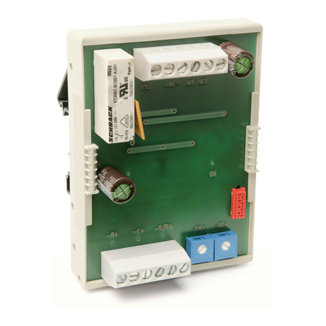
Siko
Siko MS02 User manual
Siko
Siko Easy Touch Control ETC5000 User manual
Siko
Siko AEA111/1 Operation manual
Siko
Siko ASA510 Operation manual
Siko
Siko MA523/1-S User manual

Siko
Siko AS510/1 Operation manual

Siko
Siko AS510/1 User manual
Siko
Siko AS510 Operation manual

