Econ 68 Series User manual

Installation & Operation Manual
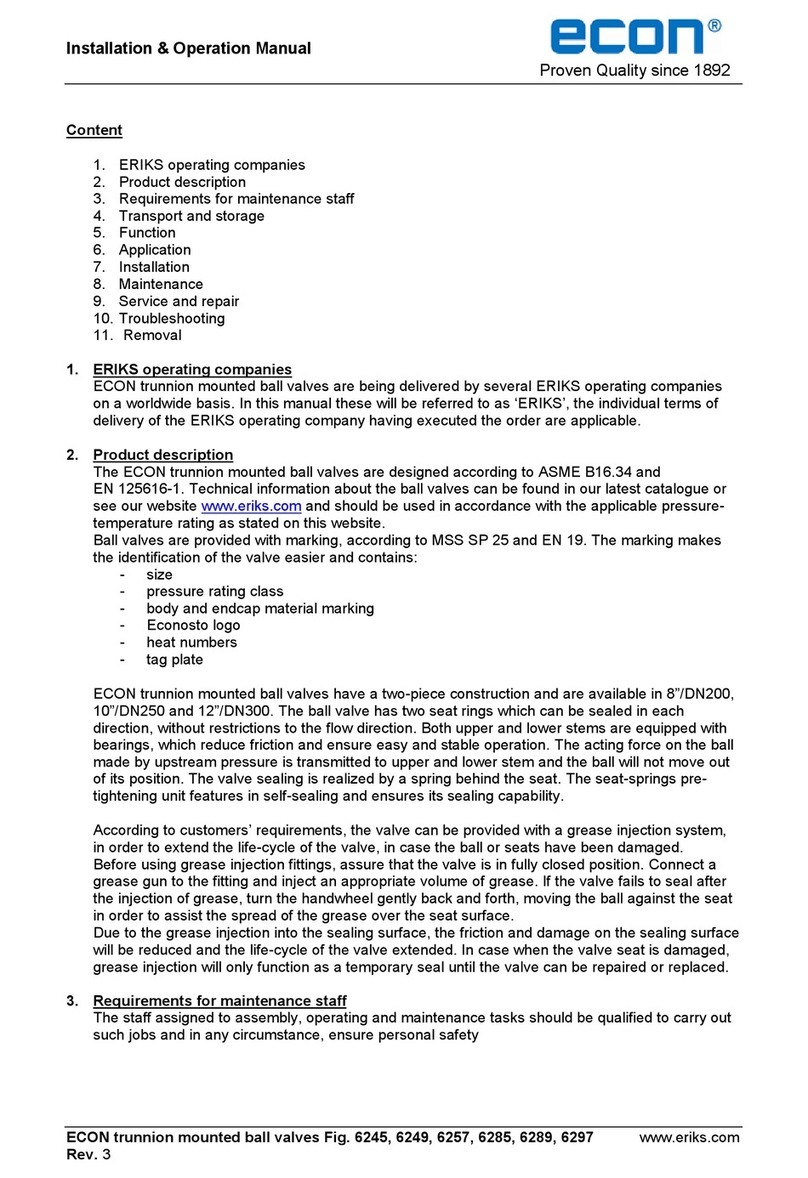
Proven Quality since 1892
ECON butterfly valves Series 67 & 68 Page 1of 6ww.eriks.com
Rev.1
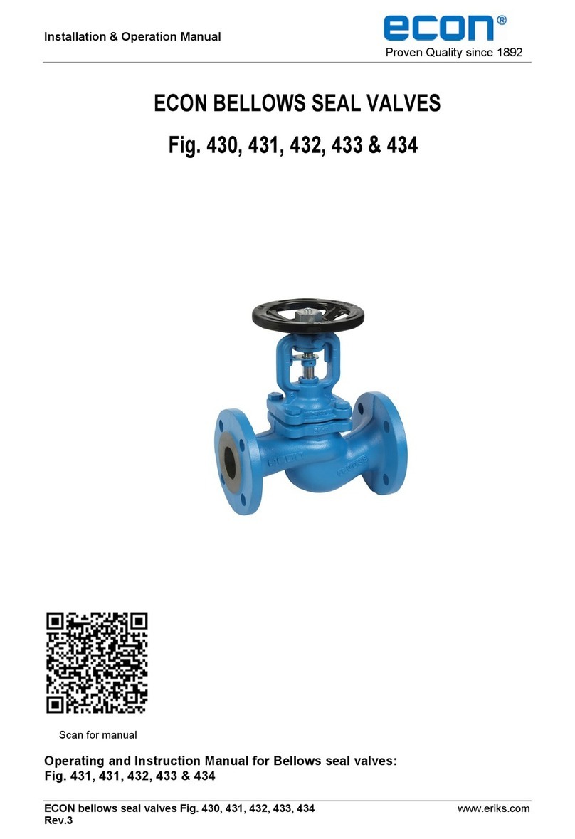
ECON BUTTERFLY VALVES
Series 67 and 68
Series 67
Series 68

Installation & Operation Manual
Proven Quality since 1892
ECON butterfly valves Series 67 & 68 Page 2of 6ww.eriks.com
Rev.1
Content
1. Introduction
2. Product description
3. Requirements for maintenance staff
4. Transport and storage
5. Function
6. Application
7. Installation
8. Maintenance
9. Cleaning of the piping
10. Service and repair
11. Troubleshooting
12. Removal
1. ERIKS operating companies
ECON butterfly valves are being delivered by several ERIKS operating companies on a worldwide
basis. In this manual these will be referred to as ‘ERIKS’, the individual terms of delivery of the
ERIKS operating company having executed the order are applicable.
In order to benefit from the excellent properties of the ECON butterfly valves Series 67 and 68 it is
necessary that the instructions of this user manual are followed carefully. For errors resulting from
improper installation ERIKS cannot be held responsible.
Fig.No.
Type
Disc
DVGW GAS
Colour
Operator
6720
Wafer
Alu-Bronze
Blue
Bare shaft
6721
Wafer
Alu-Bronze
Blue
Lever
6722
Wafer
Alu-Bronze
Blue
Gear box
6730
Wafer
Stainless Steel
Blue
Bare shaft
6731
Wafer
Stainless Steel
Blue
Lever
6732
Wafer
Stainless Steel
Blue
Gear box
67301
Wafer
Stainless Steel
Yes
Yellow
Bare shaft
67311
Wafer
Stainless Steel
Yes
Yellow
Lever
67321
Wafer
Stainless Steel
Yes
Yellow
Gear box
6820
Lug
Alu-Bronze
Blue
Bare shaft
6821
Lug
Alu-Bronze
Blue
Lever
6822
Lug
Alu-Bronze
Blue
Gear box
6830
Lug
Stainless Steel
Blue
Bare shaft
6831
Lug
Stainless Steel
Blue
Lever
6832
Lug
Stainless Steel
Blue
Gear box
68301
Lug
Stainless Steel
Yes
Yellow
Bare shaft
68311
Lug
Stainless Steel
Yes
Yellow
Lever
68321
Lug
Stainless Steel
Yes
Yellow
Gear box
2. Product description
The ECON butterfly valves are designed according the information in our latest catalogue or see
our website www.eriks.com and should be used in accordance with the applicable pressure-
temperature rating as stated on this website. ECON butterfly valves are provided with casted
markings according to EN 19. The marking makes the identification of the valve easier and
contains:
- size (DN)
- pressure rating class
- body material marking
- heat numbers (when required)
- CE marking when applicable
- ECON logo

Installation & Operation Manual
Proven Quality since 1892
ECON butterfly valves Series 67 & 68 Page 3of 6ww.eriks.com
Rev.1
3. Requirements for maintenance staff
The staff assigned to assembly, operating and maintenance tasks should be qualified to carry out
such jobs and in any circumstance, ensure personal safety.
4. Transport and storage
The valve must be transported and stored dry and clean. In humid rooms, a drying material or
heating must be used to avoid condensation. The valve is supplied with the disc in a slightly open
position. This will have to remain until the installation is complete. (Fig.1) . The paint is a base coat
to protect against corrosion during transportation and storage. Do not damage the paint protection.
Fig. 1
5. Function
ECON butterfly valves are designed for interruption or restriction of the flow of liquids and gases.
The valve is closed by turning the lever clockwise; please don’t use tools to increase the torque on
the lever.
6. Application
Please make sure that the valve intended for installation is suitable for the service conditions
prevailing. The ECON butterfly valves are used for industrial systems gases and liquids. The
valves are designed for standard operating conditions. For the use of extreme conditions e.g.
aggressive or abrasive media, it is recommended to mention this at the ordering stage, to verify
whether the valve is suitable. The installation designer is responsible for the valve selection,
suitable for the working conditions. The valves are unsuitable, without written permission of an
ERIKS company, to apply for hazardous media as referred into Regulation (EC) No 1272/2008.
7. Installation
Flange facings must be smooth and clean. Rust, welding scores, rests of paint, dirt, etc. must be
removed. ECON butterfly valves Series 67, in wafer style design, are suitable for installation
between DIN PN10, PN16 and ANSI150 flanges. Please consult our website www.eriks.com
concerning the allowed flange dimensions. For the installation of valves between flanges of other
standards consult ERIKS or its authorized distributors.
When installed in a horizontal pipeline it is recommended that the butterfly valve is to be
mounted with the stem in a horizontal position, as such that the bottom of the disc will open in
the direction of the flow. This prevents sludging of the flow and accumulation of dirt. (See
figure 2).
The contact surfaces of the flanges must be smooth and clean. Rust, spatter, dirt and paint is
to be removed to prevent damage to the lining.
Flange gaskets are not allowed to use ( See figure 3)
Please be informed that also the Lug type butterfly valves Series 68 have to be installed
between flanges and can’t be used as end of line valve.

Installation & Operation Manual
Proven Quality since 1892
ECON butterfly valves Series 67 & 68 Page 4of 6ww.eriks.com
Rev.1
← Flow direction
Fig. 2 Fig. 3
ECON butterfly valves are suitable to be built between DIN PN 10/16 and, in some cases,
ANSI 150 flanges. For the installation of valves between flanges of other standards consult
ERIKS or its authorized distributors.
ERIKS recommends to mount rubber lined butterfly valves between flanges, which have the
same inner diameter as the valves. This will extend the lifetime of the liner/seat and it will also
create an optimal flange sealing. Flanges according to EN1092-1 type 11 do meet these
requirements. Other types might cause difficulties.
The butterfly valves may not be fitted into a pipe which inner diameter is smaller than the
nominal diameter of the valve. In such case you should use spacers to prevent damage to the
disc (See figure 4).
Under no circumstances should the valve be installed between non-parallel flanges. The axes
of the pipeline and the butterfly valve must be aligned. The disc of an eccentrically mounted
butterfly valve can be damaged (See figure 5). It is also not allowed to weld the pipeline if the
valve is mounted between the flanges. This could permanently damage the valve. The flanges
should have sufficient opening so that the valve can easily be placed between the flanges.
The disc should be slightly open (See figure 6). If the opening between flanges is too close the
lining could be damaged. Insert the flange bolts while the disc is still a bit open and tighten the
bolts by hand (See figure 7). If the bolts are tightened while the valve is closed, the liner will be
incorrectly tensioned. This will increase the torque and the valve can leak. Open the butterfly
valve now completely (See figure 8) and make sure the pipeline is aligned properly. Tighten
the bolts evenly crosswise.
We recommend to operate the valve at least once a month. If this is not possible an increase
of the break torque should be taken into account. In this case the actuator selection has to be
adjusted to this higher torque. Please consult ERIKS for the correct actuator sizing.
Figure 4 Figure 5 Figure 6 Figure 7 Figure 8
8. Maintenance
The ECON butterfly valves have been designed and manufactured to obtain the maximum life and
efficiency at minimum wear. Before starting any service jobs, make sure that the medium supply to

Installation & Operation Manual
Proven Quality since 1892
ECON butterfly valves Series 67 & 68 Page 5of 6ww.eriks.com
Rev.1
the pipeline is cut off, pressure was decreased to ambient pressure, the pipeline is completely
cleaned and ventilated and the plant is cooled down. Always keep safety instructions in mind and
take all personal safety precautions.
No periodic lubrication or maintenance is required.
During maintenance, the following rules should be observed:
- always keep personal safety precautions in mind and always use appropriate protection
e.g. clothing, masks, gloves etc.
- be alert that the temperature still can be very high or low and can cause burns.
- check the valve on all possible leaking possibilities.
- check if all bolts and nuts, are still fastened.
- dust, grease and medium residual, must be frequently cleaned of the valve body and all
moving parts, such as stem to maintain all operating functions.
9. Service and repair
All service and repair jobs should be carried out by authorized staff, using suitable tools and user
shall use, bolt and nut of the same size and material as the original one.
- welding (repair) and drilling of the butterfly valve is forbidden.
- repair of the butterfly valve is not possible, because of the pinned disc and vulcanised
seat construction. Please replace the valve if damaged.
- during replacement of the butterfly valve, tighten the hexagon flange bolts (and nuts)
evenly in crosswise order.
- after replacement of the butterfly valve, it is necessary to check the valve operation and
tightness of all connections. A tightness test should be carried out.
- after installation, the valve should be checked and maintained periodically at least every
3 months, depending on the medium.
10. Troubleshooting
It is essential that the safety regulations are observed when identifying the fault.
Problem
Possible cause
Corrective measures
No flow
Flange dust caps were not
removed
Remove dust caps
Little flow
Valve not completely open
Open valve completely
Piping system clogged
Check piping system
Valve is impossible or difficult
to open or close
Service conditions (e.g.
medium, temperature) outside
permissible limits.
Replace valve.
Consult supplier.
Power failure.
Check power supply.
Wrong direction of rotation.
Turn in correct direction.
(clockwise for opening)
Fouling of the disc and/or seat
Remove fouling on the disc
and/or seat
Valve leaking
Valve not properly closed
Close valve properly or readjust
limit switch/stop screw.
Seat damaged by foreign
particles
Replace valve
Medium contaminated
Clean valve and install dirt
screen
Valve with locking device
cannot be opened.
Locking device tightened
Slacken locking device.

Installation & Operation Manual
Proven Quality since 1892
ECON butterfly valves Series 67 & 68 Page 6of 6ww.eriks.com
Rev.1
11. Removal
Before removing the valve from the pipe consider that dangerous fluids might leak. Corresponding
measures of precaution have to be applied. All dismantled and rejected valves cannot be disposed
with household waste. The valves are made of materials which can be re-used and should be
delivered to designated recycling centres.
General warning:
General note for products which may be used for seawater:
Although our products can be used in seawater systems it should always be noted that, in case of
installation in a piping system made of materials which are frequently used because of their excellent
seawater resistance (e.g. Cunifer), large potential differences may occur possibly causing corrosion
which could permanently damage the proper functioning and integrity of our product.
A combination of different materials should always be mentioned prior to the purchase of our products
in order for us to give the best possible advice on a safe functioning.
This manual suits for next models
19
Table of contents
Other Econ Control Unit manuals
