mru MF Plus User manual

MRU GmbH USER MANUAL MFplus Part 2 OPTION TRGI
1

MRU GmbH USER MANUAL MFplus Part 2 OPTION TRGI

MRU GmbH USER MANUAL MFplus Part 2 OPTION TRGI
3
1Table of content
1 Table of content ...................................................................................................................................................................3
2 Introduction .........................................................................................................................................................................5
3 Pipe tests(TRGI)....................................................................................................................................................................6
3.1 Stress test..................................................................................................................................................................7
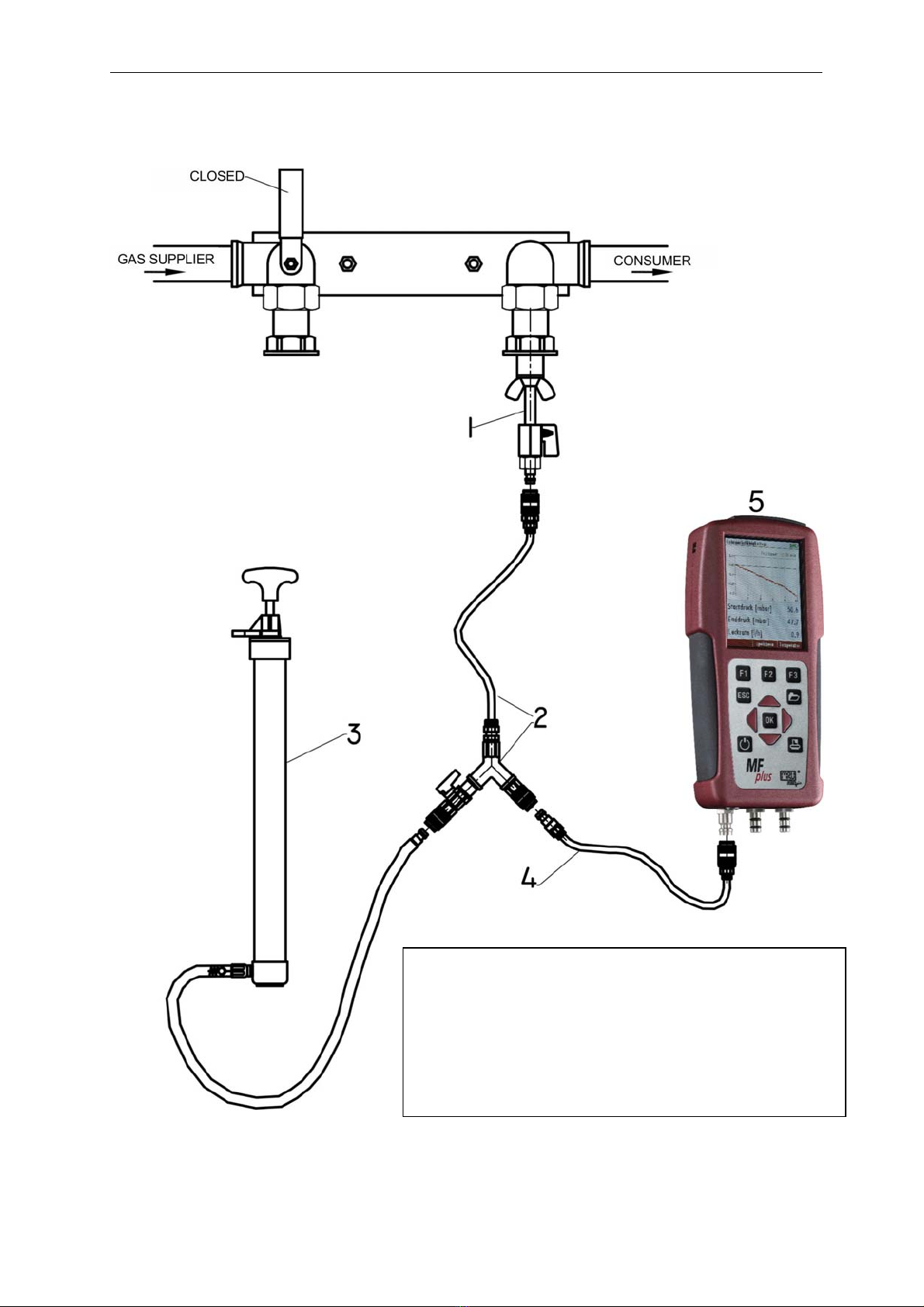
3.1.1 Connection diagram stress test LOAD side only ...................................................................................................8
3.1.2 Connection diagram stress test LOAD side and GAS supplier side .......................................................................9
3.1.3 Operation ...........................................................................................................................................................10
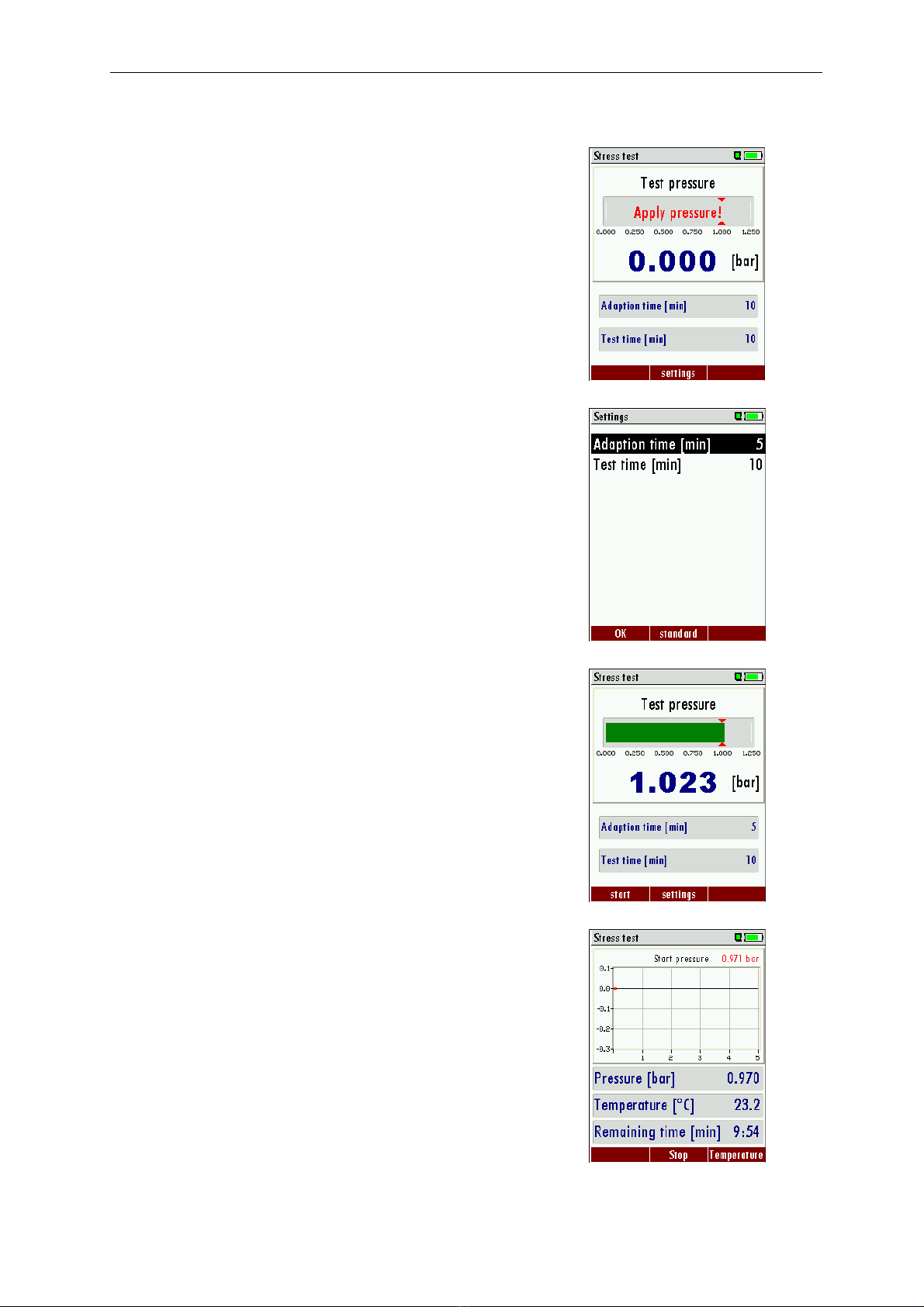
3.1.3.1 Apply pressure..........................................................................................................................................10
3.1.3.2 Adaption phase ........................................................................................................................................10
3.1.3.3 Test phase ................................................................................................................................................11
3.1.3.4 View results..............................................................................................................................................11
3.1.3.5 Save results ..............................................................................................................................................12
3.2 Leak-tightness test ..................................................................................................................................................13
3.2.1 Connection diagram leak-tightness test LOAD side only....................................................................................14
3.2.2 Connection diagram leak-tight test Load side and Gas supplier side .................................................................15
3.3 Operation ................................................................................................................................................................16
3.3.1.1 Apply pressure..........................................................................................................................................16
3.3.1.2 Adaption phase ........................................................................................................................................16
3.3.1.3 Test phase ................................................................................................................................................16
3.3.1.4 View results..............................................................................................................................................17
3.4 Usage capability tests..............................................................................................................................................18
3.4.1 Connection diagram usage capability test LOAD side only.................................................................................19
3.4.2 Connection diagram usage capability test without dismounting gas meter.......................................................20
3.4.3 Connection diagram usage capability test LOAD side only test with air.............................................................21
3.4.4 Connection diagram usage capability test LOAD side and Gas supplier side test with air .................................22
3.4.5 Connection diagram example with the optional Black box TRGI........................................................................23
3.4.6 Operation ...........................................................................................................................................................24
3.4.6.1 Automatic capacity determination using the optional Black box TRGI (Option).......................................24
3.4.6.2 Automatic capacity determination ...........................................................................................................25
3.4.6.3 Enter pipe capacity manually ...................................................................................................................26
3.4.6.4 Enter all other parameters........................................................................................................................26
3.4.6.5 Apply test pressure...................................................................................................................................26
3.4.6.6 Adaption phase ........................................................................................................................................27
3.4.6.7 Test phase ................................................................................................................................................27
3.4.6.8 View results..............................................................................................................................................27
3.4.6.9 Save results ..............................................................................................................................................28
3.5 Pipe tests TRGI 50 mbar..........................................................................................................................................30
3.5.1 Connection diagram pipe test ............................................................................................................................30
3.5.2 Operation ...........................................................................................................................................................30
3.5.2.1 Apply pressure..........................................................................................................................................31

MRU GmbH USER MANUAL MFplus Part 2 OPTION TRGI
4
3.5.2.2 Adaption phase ........................................................................................................................................31
3.5.2.3 Pressure test.............................................................................................................................................31
3.6 Liquid gas pipes (TRF) .............................................................................................................................................32
3.6.1 Operation ...........................................................................................................................................................32
3.6.2 Stability test TRF.................................................................................................................................................33
3.6.2.1 Apply pressure..........................................................................................................................................33
3.6.2.2 Adaption phase ........................................................................................................................................34
3.6.2.3 Pressure test.............................................................................................................................................34
3.6.3 Leak-tight test (TRF)...........................................................................................................................................35
3.6.3.1 Apply pressure..........................................................................................................................................35
3.6.3.2 Adaption phase ........................................................................................................................................35
3.6.3.3 Pressure test.............................................................................................................................................36
4 Accessories.........................................................................................................................................................................37
4.1 Measuring accessory- Set 1, for ONE pipe gas meter # 61500 ................................................................................37
4.2 Measuring accessory- Set 2, for TWO pipe gas meter # 61501 ...............................................................................37
4.3 Connection set SMALL only for usage capability test # 64072 ................................................................................37
4.4 Additional accessory ...............................................................................................................................................37
4.5 Optionen .................................................................................................................................................................38
5 Technical details MFplus Option TRGI................................................................................................................................39
5.1 Sensor specifications pressure measurement ..........................................................................................................39
5.2 Calculated value gas leakage rate...........................................................................................................................39
5.3 Additional specifications .........................................................................................................................................39
6 Usage capability test..........................................................................................................................................................40
6.1 What is a Usage capability test ...............................................................................................................................40
6.2 Connection diagram Usage capability test without dismounting gas meter using SET #64072 (small)...................41
6.3 Operation ................................................................................................................................................................42
6.3.1 Automatic capacity determination .....................................................................................................................42
6.3.2 Enter pipe capacity manually .............................................................................................................................43
6.3.3 Enter all other parameters..................................................................................................................................43
6.3.4 Apply test pressure.............................................................................................................................................43
6.3.5 Adaption phase ..................................................................................................................................................44
6.3.6 Test phase ..........................................................................................................................................................44
6.3.7 View results........................................................................................................................................................45
6.3.8 Save results ........................................................................................................................................................46

MRU GmbH USER MANUAL MFplus Part 2 OPTION TRGI
5
2Introduction
This manual is an important element of the delivery and explains in detail how to operate the MFplus but also
ensures the safety of the user and protects the environment.
This manual „USER MANUAL MFplus Part2 TRGI“ only addresses the TRGI functions.
For the general operation of the MFplus the manual „USER MANUAL MFplus” is essential!
It is the duty of each user to get familiar with the contents of these manuals and to follow the directions
especially regarding security.
This device must always be used according to the latest DVGW regulations!
The MFplus TRGI is used to determine gas leakage in low pressure gas tubes according to DVGW-worksheet G
600 (DVGW-TRGI)
The gas leakage rate will be determined according to device class D based on the pressure drop.
For the pressure the unit mbar and bar are used.
1 mbar <> 1 hPa
Before starting a measurement the device and accessories must be inspected for any damages. A
measurement is only possible after the zeroing procedure has been accomplished successfully.
The zeroing takes between 1 and 3 minutes (depending on sensor condition) and should be made in the
recommended measuring position.
For best visibility and operation the device can either be lying flat on the back or can be hanging using the
rear magnets. The position of the device doesn’t influence the test results (accuracy).
OVERLOAD
ATTENTION:
The device is protected against overload up to 2 Bar. In case the overload value is exceeded the pressure
sensor can be destroyed. In that case the warranty for this device will expire.
Calibration
The MFplus TRGI must be calibrated on a yearly basis.

MRU GmbH USER MANUAL MFplus Part 2 OPTION TRGI
6
3Pipe tests(TRGI)
The option pipe test (TRGI) includes the following tests:
•PRE test on gas pipes according to TRGI G 600
•Leak tightness test on gas pipes according to TRGI G 600
•Usage capability test- / Leakage rete measurement according to TRGI G 600, incl. determination of
the pipe capacity
In the Measurement menu select Pipe test and confirm with OK
In the menu Pipe tests select the desired test and confirm with OK.

MRU GmbH USER MANUAL MFplus Part 2 OPTION TRGI
7
3.1 Stress test
The stress test serves as loading test of the materials.
All new installed pipes will be tested without the use of faucets. All pipe ends must be closed with metal
plugs or caps.
Exception: The stress test can be carried out with faucets if their maximal pressure range is equivalent or
higher than the test pressure.
The stress test should be done as long as the pipes are still accessible and before they are covered with any
anti-freeze protection.
The test pressure is 1 bar (1.000 hPa).
The test medium is either air or a not burnable gas, NO Oxygen!
The test phase is usually 10 minutes. Temperature compensation is not mandatory but dependent on the
length of the pipes and the temperature difference between the test medium and the pipes - temperature
compensation is recommended.
Thereafter, the test pressure may not decrease within 10 minutes. During the test phase the pipes are to be
visually inspected, connections and junctions should be mechanically stressed.
It is forbidden to connect any test pipes with gas filled pipes!!
On the following pages different connection diagrams are shown.

MRU GmbH USER MANUAL MFplus Part 2 OPTION TRGI
8
3.1.1 Connection diagram stress test LOAD side only
1 # 59148 Test plug
2 # 59074 Y-Divider with tap
3 # 59072 Hand pump
4 # 59076 Hose from MFplus to divider
5 MFplus

MRU GmbH USER MANUAL MFplus Part 2 OPTION TRGI
9
3.1.2 Connection diagram stress test LOAD side and GAS supplier side
1 # 59148 Test plug (2x)
2 # 59074 Y-Divider with tap and hose
3 # 59072 Hand pump
4 # 59076 Hose from MFplus to divider
5 # 59320 Y-Divider without tap with hose
6 MFplus

MRU GmbH USER MANUAL MFplus Part 2 OPTION TRGI
10
3.1.3 Operation
3.1.3.1 Apply pressure
In this screen you will apply pressure to the pipe you want to test.
Using the hand pump you will apply pressure (air) with open tap at the
Y-divider (2).
Times can be modified with the F2 button.
Times between 1 minute and 80 minutes are selectable.
The default value is 10 minutes.
Once the test pressure of 1 Bar is reached, the bar on the screen turns
green and the tap at the Y-divider (2) must be closed. With F1 the test
will be started.
3.1.3.2 Adaption phase
The adaption phase can be shortened at any time using the F1 button.
With F3 the temperature curve will be displayed.
Once the adaption phase is completed the stress test will start
automatically.

MRU GmbH USER MANUAL MFplus Part 2 OPTION TRGI
11
3.1.3.3 Test phase
Now the stress test is in operation. Also here F3 will make the
temperature curve visible.
The temperature curve will help judging the test result. A decreasing
temperature during the test phase can result in a low pressure drop.
There is no automatic pressure/temperature compensation!
3.1.3.4 View results
At the end of the test the start pressure, end pressure and pressure
difference will be displayed.
With the printer button the results can be printed.
With the F2 button the results can be saved.
With ESC you will return to the measuring menu.

MRU GmbH USER MANUAL MFplus Part 2 OPTION TRGI
12
Example print-out of a Stress test
3.1.3.5 Save results
Here you will select the site under which the results will be saved.
Press F3 to save the results to the site.
Saved results can be viewed again.
With ESC you will return to the measuring menu.

MRU GmbH USER MANUAL MFplus Part 2 OPTION TRGI
13
3.2 Leak-tightness test
With the leak-tightness test smallest leaks can be made vissible.
The pipes with all faucets are tested, however without gas units and their regulators and security devices. The
gas meter can be included in this test.
The leak-tight test should be done as long as the pipes are still accessible and before they are covered with
any anti-freeze protection.
Test pressure: 150 mbar (150 hPa)
Test medium: Air or inert gas
Test duration: Dependent on the pipe capacity one must consider the adaption time and a
minimum test duration time is mandatory
Pipe capacity: Adaption phase: Test duration:
<100l 10min 10min
>=100 <200l 30min 20min
>=200l 60min 30min
On the following pages different connection diagrams are shown.

MRU GmbH USER MANUAL MFplus Part 2 OPTION TRGI
14
3.2.1 Connection diagram leak-tightness test LOAD side only
1 # 59148 Test plug
2 # 59074 Y-divider with tap and hose
3 # 59071 Pump ball with outlet valve and
balancing balloon
4 # 59076 Hose from MFplus to Y-divider
5 MFplus

MRU GmbH USER MANUAL MFplus Part 2 OPTION TRGI
15
3.2.2 Connection diagram leak-tight test Load side and Gas supplier side
1 # 59148 Test plug (2x)
2 # 59074 Y-divider with tap and hose
3 # 59076 Pump ball with outlet valve
and balancing balloon
4 # 59071 Hose from MFplus to Y-
divider
5 # 59320 Y-divider without tap with
hose
6 MFplus

MRU GmbH USER MANUAL MFplus Part 2 OPTION TRGI
16
3.3 Operation
3.3.1.1 Apply pressure
In this screen you will apply pressure to the pipe you want to test.
Pump air into the system using the pump ball – tap at Y-divider (2)
must be open.
Once the test pressure of 150 mbar is reached, the bar on the screen
turns green and the tap at the Y-divider (2) must be closed. With F1 the
test will be started.
3.3.1.2 Adaption phase
The adaption phase can be shortened at any time using the F1 button.
With F3 the temperature curve will be displayed.
Once the adaption phase is completed the leak-tight test will start
automatically.
3.3.1.3 Test phase
Now the stress test is in operation. Also here F3 will make the
temperature curve visible.

MRU GmbH USER MANUAL MFplus Part 2 OPTION TRGI
17
The temperature curve will help judging the test result. A decreasing
temperature during the test phase can result in a low pressure drop.
There is no automatic pressure/temperature compensation!
3.3.1.4 View results
At the end of the test the start pressure, end pressure and pressure
difference will be displayed.
With the printer button the results can be printed.
With the F2 button the results can be saved.
With ESC you will return to the measuring menu.
Example print-out of a leak-tight test

MRU GmbH USER MANUAL MFplus Part 2 OPTION TRGI
18
3.4 Usage capability tests
The Usage capability test helps to determine and judge leakages (gas leakage) in low pressure gas pipes.
Tested will be all in operation or repaired pipes with all faucets, however without gas units and their
regulators and security devices. The gas meter can be included in this test (using backward test).
The usage capabilities test my not be performed when:
- New installed pipes (= pipes within warranty)
- Pipes that had a limited usage capability or a NO usage capability and had been repaired to be used
- Not in use pipes which want to be used again
- Pipes in middle- and high pressure range.
Test medium: Air or Methane
Test pressure: 23 mbar according to DVGW worksheet G600.
Unlimited usage capability: > 0 l/h to < 1,0 l/h
The pipe can be used for unlimited time without repair.
Limited usage capability: >1,0 l/h up to < 5,0 l/h
The pipe may be used for a maximum of 4 weeks. Within these 4 weeks the pipe must be repaired to achieve
Unlimited Usage Capacity again (Leak-tight test).
NO usage capability: > 5,0 l/h
The use of this pipe must be stopped immediately. Take action to determine the defect.
Important is the technical security judgment:
Also a leak tight gas pipe can have limited or no usage capability. The physical condition must be considered
as well!
Once you smell gas the system is leaking. The above mentioned usage capability grading’s do not apply.

MRU GmbH USER MANUAL MFplus Part 2 OPTION TRGI
19
On the following pages different connection diagrams are shown.
3.4.1 Connection diagram usage capability test LOAD side only
108 ml =
syringe NOT pulled
1 # 59148 Test plug
2 # 59074 Y-Divider with tap and hose
3 # 59076 Hose from MFplus to Y-divider
4 #59038 Connector
5 #50482 Silicone hose
6 # 61499 Syringe
7 MFplus

MRU GmbH USER MANUAL MFplus Part 2 OPTION TRGI
20
3.4.2 Connection diagram usage capability test without dismounting gas meter
108 ml =
Syringe NOT pulled
1 # 59387 Test connection
2 # 50482 Silicone hose
3 # 59074 Y-Divider with tap and hose
4 # 59076 Hose from MFplus to Y-Divider
5 # 50482 Silicone hose
6 # 61499 Syringe
7 # 59038 Connector
8MF
p
lus
Table of contents
Other mru Measuring Instrument manuals

mru
mru MGAprime User manual

mru
mru SWG100 CEM User manual

mru
mru OPTIMA Biogas User manual

mru
mru SWG 100 SYNGAS User manual

mru
mru SWG 100 User manual

mru
mru SYNGAS VARIOluxx User manual

mru
mru SWG 100 biogas User manual

mru
mru VARIOluxx User manual

mru
mru OPTIMA7 biogas User manual

mru
mru DM 9600 CHP User manual
Popular Measuring Instrument manuals by other brands

airmaster
airmaster OZONE MONITOR instruction manual

Applied Instruments
Applied Instruments XR-3 Application note

Keithley
Keithley 3321 Operator's manual

HANYOUNG NUX
HANYOUNG NUX MP3-4 H Series instruction manual

Digi-Sense
Digi-Sense 20250-14 user manual

B+K precision
B+K precision 8500B Series user manual