FIC PAK-2005 User manual

PAK-2005
MAINBOARD
USER’S MANUAL
DOCUMENT No. : 16069
MANUAL REVISION : A1
RELEASE DATE : December, 1997
PRODUCT PART No.: 25–10813–01

PAK-2005
Handling Precautions
WARNING:
1. Static electricity may cause damage to the integrated circuits on the
mainboard.
Before handling any mainboard outside of its protective packaging,
ensure that there is no static electric charge in your body.
2. There is a danger of explosion if the battery is incorrectly replaced.
Replace only with the same or an equivalent type recommended by
the manufacturer.
3. Discard used batteries according to the manufacturer’s instructions.
Observe the following basic precautions when handling the mainboard or
other computer components:
nWear a static wrist strap which fits around your wrist and is connected to
a natural earth ground.
nTouch a grounded or anti-static surface or a metal fixture such as a water
pipe.
nAvoid contacting the components on add-on cards, boards and modules
and with the “gold finger” connectors plugged into the expansion slot. It
is best to handle system components by their mounting bracket.
The above methods prevent static build-up and cause it to be discharged
properly.
Trademarks™
All trademarks mentioned in this manual are mentioned for identification
purposes only. Product names appearing in this manual may or may not be
registered trademarks or copyrights of their respective companies.
Intel and Pentium are registered trademarks of Intel Corporation.
Windows and MS-DOS are registered trademarks of Microsoft Corporation.
Copyright ©
No part of this manual, including the product and software may be
reproduced, transmitted, transcribed, stored in a retrieval system, or
translated into any language in any form by any means without the express
written permission of FIRST INTERNATIONAL COMPUTER, INC.
(hereinafter referred to as FIC) except documentation kept by the purchaser
for backup purposes.
Notice

PAK-2005 Mainboard Manual
PAK-2005
Specifications are subject to change without notice. FIC provides this manual
“as is” without warranty of any kind, either express or implied, including but
not limited to the implied warranties or conditions of salability or fitness for
a particular purpose. In no event shall FIC be liable for any loss or profits,
loss of business, loss of use or data, interruption of business, or for indirect,
special, incidental, or consequential damages arising from any defect or error
in this manual or product. FIC may revise this manual from time to time
without notice.
For the previous or updated manuals, BIOS, drivers, or product release
information you may visit FIC’s homepage at: http://www.fic.com.tw/.
©Copyright 1997 FIRST INTERNATIONAL COMPUTER, INC. All rights
reserved.

i
Chapter 1 Overview
Main Features........................................................................................ 2
Advanced Features................................................................................. 3
Package Checklist.................................................................................. 5
Mainboard Layout (with onboard COM1 and COM2 ports).................... 6
Mainboard Layout (with onboard USB port)........................................... 7
This User’s Manual................................................................................ 8
Something Interesting............................................................................. 8
The BIOS Setup Utility................................................................. 9
IRQ Functionality.......................................................................... 9
DMA Channels of ISA Cards ........................................................ 10
Enhanced IDE............................................................................... 10
Infrared Connections..................................................................... 10
Highly Convenient Integrated I/O Connectors................................ 11
Chapter 2 Installation Procedures
Mainboard Layout (with onboard COM1 and COM2 ports).................... 14
Mainboard Layout (with onboard USB port)........................................... 15
1). Set System Jumpers .......................................................................... 16
Jumpers ........................................................................................ 16
Clear Password: CPW............................................................ 17
Flash EPROM Type Selection: EP1, EP2............................... 17
CPU to SRAM Data Transaction Mode Selection: SRAM1 .... 18
VGA Selection: VGA1........................................................... 18
2). Install System RAM Modules............................................................ 19
DRAM Memory............................................................................ 19
DRAM Module Configuration....................................................... 20
Install SIMMs............................................................................... 21
Remove SIMMs............................................................................ 22
Install DIMMs .............................................................................. 22
Remove DIMMs............................................................................ 23
Cache Memory.............................................................................. 23
Option 1: 512KB Cache SRAM ............................................. 23
Option 2: 256KB Cache SRAM ............................................. 24
Option 3: 512KB Cache SRAM ............................................. 24
Option 4: 1MB Cache SRAM ................................................ 25
Table of Contents

PAK-2005 Mainboard Manual
ii
3). Install the Central Processing Unit (CPU) ......................................... 25
Select Frequency and Voltage...................................................... 27
CPU to Bus Frequency Ratio: FREQ1, FREQ2, FREQ3......... 27
CPU External Clock (Bus) Frequency: CLK1, CLK2, CLK3 .. 28
Intel Pentium CPUs............................................................... 29
Frequency......................................................................... 29
Voltage............................................................................. 30
AMD-K5/K6 CPUs................................................................ 31
Frequency......................................................................... 31
Voltage............................................................................. 32
Cyrix 6x86/6x86MX / IBM 6x86/6x86MX CPUs .................. 33
Frequency......................................................................... 33
Voltage............................................................................. 34
4). Install Expansion Cards .................................................................... 35
Assigning IRQs for Expansion Cards ........................................... 37
Assigning DMA Channels for ISA Cards ..................................... 37
5). Connector Cables and Power Supply................................................. 38
Connectors .................................................................................. 38
Floppy Diskette Drive Connector (34-pin block): FLOPPY .... 38
Infrared Connector: IR ........................................................... 39
Serial Port Connectors (Two 9-pin Male): COM1, COM2...... 39
Serial Port and Serial Connector: COM1, COM2_E............... 40
Standard Power Connector: POWER...................................... 40
IDE HDD Device Connector: PRIMARY, SECONDARY....... 41
Universal Serial Bus Port: USB (with onboard USB port) ...... 42
Universal Serial Bus Connector: USB.................................... 42
PS/2 Keyboard Connector (6-pin Female): PS2_KB............... 43
PS/2 Mouse Connector (6-pin Female): PS2_MS ................... 43
Remote Power Supply Connector: RPW_CON1 ..................... 44
CPU Fan Connector: CHASIS FAN, CPU_FAN..................... 45
Front Panel Block Connector: F_PNL .................................... 46
LAN System Wakeup Connector: LAN_WAKE ..................... 47
System Chassis Open Alarm Connector: CHASIS .................. 48
VGA Feature Connector: FEATURE...................................... 48
VGA Connector: VGA........................................................... 49
Parallel Printer Connector (25-pin Female): PRINTER........... 49
Power Connection Procedures ................................................................ 50
Powering Off the Computer.................................................................... 50

Table Of Contents
iii
Chapter 3 Setting BIOS Feature
Main CMOS Setup................................................................................. 52
Load Defaults.............................................................................. 52
Standard CMOS Setup........................................................................... 52
Auto Detection of Hard Disks on Bootup ..................................... 54
BIOS Features Setup.............................................................................. 55
Chipset Features Setup........................................................................... 58
Power Management Setup...................................................................... 60
PNP and PCI Setup ................................................................................ 63
Load BIOS Defaults............................................................................... 64
Load Setup Defaults............................................................................... 65
Integrated Peripherals ............................................................................ 65
Supervisor Password and User Password................................................ 68
IDE HDD Auto Detection....................................................................... 69
Save & Exit Setup.................................................................................. 70
Exit Without Saving............................................................................... 70

PAK-2005 Mainboard Manual
iv
— This Page Intentionally Left Blank —

1
Overview
Based on the new highly integrated VIA VT82C590 VP2, the PAK-2005 mainboard
combines blistering Intel Pentium® processor performance with support for
intelligent diagnostic and power management features to provide a powerful and
versatile LPX-size platform for leading-edge PC ‘97 compliant multi-media
systems.
With its switching voltage regulator, the PAK-2005 runs a complete range of Intel
Pentium® processors, including the Intel Pentium processor with MMX™
technology, as well as the AMD-K5™/-K6™ and Cyrix/IBM 6x86™/6x86MX™
processors. For added power and performance, the PAK-2005 takes up to 1MB
Pipeline Burst Level II cache and up to 256MB DRAM via two 72-pin SIMM
sockets and two 168-pin DIMM sockets which accepts high-speed EDO, and
lightning-fast SDRAM memory types.
Built on the highly concise LPX form factor, the PAK-2005 comes with a full set of
I/O features conveniently integrated on the rear I/O panel. The board also has an
integrated PCI Bus Master Enhanced IDE controller with support for the new Ultra
DMA/33 protocol, which doubles ATA-2 Hard Disk Drive data transfer rates to
33MB/sec while maintaining full backwards compatibility with existing PIO Mode
3, PIO Mode 4 and DMA Mode 2 devices.
Fully compliant with the Microsoft PC’97 standard at both the hardware and BIOS
levels, the PAK-2005 comes with support for intelligent Hardware Monitoring and
DMI features which continuously check the thermal status of your system and
reduce the cost of ownership through improved manageability.
The S3® Trio64 V2/DX™ VGA controller offers 135MHz output pixel data rates
with non-interlaced screen resolutions of up to 1280x1024x256 colors at 75Hz
(2MB video RAM). The S3 Trio64 enables the system to have a higher performance
under Windows and other GUI (Graphics User Interface) environments.
This chapter gives a you a brief overview of the PAK-2005 mainboard. In addition
to basic information on the board's main components and features, it also provides
advice on how to upgrade and expand it. For updated BIOS, drivers, or product
release information, please visit FIC's home page at: http://www.fic.com.tw.
Congratulations on your decision to adopt the PAK-2005 mainboard. With its high-
speed EISA local bus architecture and ultra-fast I/O connections, the PAK-2005
provides the ultimate solution for optimizing the performance of your high-end
system.
Chapter 1

PAK-2005 Mainboard Manual
2
Main Features
The PAK-2005 mainboard comes with the following high-performance features:
nEasy Installation
Award BIOS with support for Plug and Play, auto detection of Hard Drive and IDE
features, MS Windows 95®, and Windows NT® compatible to make setup of hard
drives, expansion cards, and other devices virtually automatic.
nFlexible Multi-Processor/Multi-Speed Support
Onboard 321-pin ZIF socket and switching voltage regulator supports a complete
range of leading-edge processors:
Intel Pentiumwith MMXtechnology (P55C) 166/200/233 MHz processors.
Intel Pentium(P54C/P54CS) 90/100/120/133/150/166/200 MHz processors.
Cyrix6x86PR133+ - PR166+ (Rev 2.7 and later) processors.
Cyrix6x86MXPR166-PR266 processors.
AMD-K590-200MHz processors.
AMD-K6166-300MHz processors.
nVarious External Bus and CPU to Bus Frequency Ratio Support
The mainboard supports the Bus frequency for 55 / 60 / 66.6 MHz and CPU to Bus
frequency ratio of 1x / 1.5x / 1.75x / 2x / 2.5x / 3x / 3.5x / 4x / 4.5x. (Refer to
Select Frequency and Voltage of Chapter 2 for more information.)
nLeading Edge Chipset
VIA VT82C590 VP2 chipset, including a CPU interface controller, advanced cache
controller, integrated DRAM controller, synchronous EISA bus controller,
integrated power management unit.
nUltra-fast Level II Cache
Supports 256KB/512KB/1MB (onboard 512KB) synchronous Pipelined Burst
SRAM direct-mapped write-back cache memory.
nVersatile Main Memory Support
Accepts up to 256MB RAM in two banks using 72-pin Fast Page Mode (FPM) or
Extended Data Out (EDO) SIMMs of 4, 8, 16, 32, 64MB or using two 168-pin
3.3Volt DIMMs for SDRAM or EDO memory modules up to 128MB. SIMMs and
DIMMs cannot be used at the same time.
nEISA Expansion Slot
One 32-bit EISA expansion slot provides all the room you need to install a full
range of add-on cards by first inserting a riser card.
nUSB Support
Onboard support for two Universal Serial Bus connectors via a plug-in connector.

Overview
3
nEnhanced Master Mode PCI IDE Controller
Comes with an onboard Ultra DMA/33 Bus Master IDE controller with two
connectors that supports four IDE devices such as Hard Disk via two channels for
high speed (33MB/sec) data throughput. This controller supports PIO Modes 3 and
4, and Bus Master IDE DMA Mode 2 for optimized system performance.
nSuper Multi I/O
Integrated SMC FDC37C932 Plug and Play Super I/O chipset features two high-
speed 16550A UART compatible serial ports, one EPP/ECP capable parallel port,
one IR port, and one Floppy Disk Drive connector. UART2 can also be directed
from COM2 to the Infrared Module for wireless connections.
nOnboard IrDA Connector
An optional infrared port module for wireless interface is available.
Advanced Features
This mainboard comes equipped with the most advanced new features that not only
optimize the performance of the latest processors but also enhance the
manageability, power management capabilities, and user-friendliness of your
system. This section provides detailed information on these features, and how they
are implemented on the mainboard.
nOptimized Intel MMX™ Performance
The mainboard utilizes the advanced features of the VIA VT82C590 VP2 to
optimize the unrivaled performance of the Intel Pentium® processor with MMX™
technology, allowing you to enjoy a richer video, audio, digital imaging and
communications experience from the latest generation of multimedia software. To
provide you with additional flexibility, the mainboard also supports other leading-
edge processors featuring Intel’s MMX™ technology, including the AMD-K6™
processor.
nLightning-Fast SDRAM Performance
The mainboard supports the new generation of lightning-fast SDRAM
(Synchronous Dynamic Random Access Memory) via its two onboard 168-pin
DIMM sockets. SDRAM delivers an added boost to overall system performance by
increasing the CPU-to-memory data transfer rate to 528MB/sec compared to
264MB/sec for conventional EDO DRAM. SDRAM performance on the PAK-2005
is further boosted by the mainboard’s integrated IC controller, which optimizes the
memory timing settings.

PAK-2005 Mainboard Manual
4
nBlistering Ultra DMA/33 Hard Disk Drive Performance
With its integrated Enhanced PCI Bus Master IDE controller that supports the new
Ultra DMA/33 protocol, this mainboard doubles Hard Disk Drive data transfer
rates to 33MB/sec, compared to 16MB/sec for conventional PIO Mode 3, PIO
Mode 4, and DMA Mode 2 devices. By reducing the CPU’s workload and
increasing CPU utilization, Ultra DMA/33 significantly improves system
performance when running applications under Windows 95® and Windows NT®
environments. The Ultra DMA/33 protocol is completely backward compatible
with conventional ATA-2 Hard Disk Drive devices; so the mainboard also supports
existing PIO Mode 3, PIO Mode 4 and DMA Mode 2 devices using the same cable.
With the integrated Enhanced PCI Bus Master IDE controller you can connect up to
four Enhanced IDE peripheral devices to your system. All devices are categorized
in the same way that IDE hard disks were configured in the past, with one device
set as the master device and the other as the slave device. We recommend that
Hard Disk Drives use the primary IDE connector and that CD-ROM Drives utilize
the secondary IDE connector for optimum system performance.
nConcurrent PCI Architecture
The mainboard’s Concurrent PCI Architecture enables more efficient operation of
CPU, PCI and ISA transactions for faster and smoother multimedia performance. It
also allows the use of PCI 2.1 and 2.0 compatible add-in cards for long system life,
built-in scalability and the flexibility to adapt your system for future applications.
nPC ‘97 Compliant
This mainboard is fully compliant with the new PC ‘97 standard at both the BIOS
and hardware levels. PC ‘97 is a set of hardware, Bus and device design
requirements set by Microsoft in conjunction with other industry leaders aimed at
making PCs easier to use by maximizing cooperation between the operating system
and hardware.
The system design requirements under PC ‘97 supports a synergy among PC
hardware, Microsoft Windows® Operating Systems, and Windows®-based
software. Key elements include support for Plug and Play compatibility and power
management for configuring and managing all system components, and 32-bit
device drivers and installation procedures for both Windows® 95 and Windows®
NT.

Overview
5
Package Checklist
Please check that your package contains all the items listed below. If you discover
any item is damaged or missing, please contact your vendor.
þThe PAK-2005 mainboard
þThis user’s manual
þSupport software drivers and utilities
þOne floppy disk drive ribbon cable
þOne IDE hard disk drive ribbon cable
þOne COM2 cable (optional – if the current mainboard has an
onboard USB port)
þOne USB cable (optional – if the current mainboard has an
onboard COM1 and COM2 port)
PAK-2005 Mainboard Manual
6
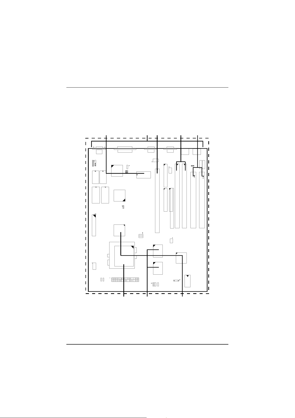
Mainboard Layout
(with onboard COM1 and COM2 ports)
I
n
t
e
g
r
a
t
e
d
I/O
Connectors
F
l
a
s
h
ROM
BIOSDIMM
SocketsSIMM
Sockets
CPU
Socket512KB
Cache
RAM
[PAK-2005 photo]
A
VIA
VT82C590 VP2
Chipset
E
I
S
A
Bus
Slot

Overview
7
Mainboard Layout (with onboard USB port)
F
l
a
s
h
ROM
BIOS
I
n
t
e
g
r
a
t
e
d
I/O
ConnectorsDIMM
SocketsSIMM
Sockets
CPU
Socket512KB
Cache
R
A
M
[PAK-2005 photo]
B
VIA
VT82C590 VP2
C
h
i
p
s
e
t
E
I
S
A
Bus
Slot

PAK-2005 Mainboard Manual
8
This User’s Manual
This manual is designed to guide you and facilitate your use of the PAK-2005
mainboard. It contains a description of the design and features of the mainboard,
and also includes useful information for changing the configuration of the board and
the system it is installed in. The manual is divided into three chapters, which
contain the main body of information normally referred to by users.
nChapter 1 — Overview
gives an overview of the mainboard and describes its major components and
features.
nChapter 2 — Installation Procedures
gives instructions on how to set up the mainboard, including jumper settings and
CPU installation guides.
nChapter 3 — Award BIOS Setup
briefly explains the mainboard’s BIOS system setup in general and tells you how to
run it and change the system configuration settings.
NOTE : The materials in this manual are for information only and is subject to
change without notice. We reserve the right to make changes in the
product design without reservation and without notification to its
users. We shall not be liable for technical or editorial omissions made
herein; nor for incidental or consequential damages resulting from the
furnishing, performance, or use of this material.
Something Interesting
This section provides useful information that you will need to know should you
decide to modify or upgrade the configuration of the mainboard and the system it is
installed in. If you do not have the confidence to upgrade the mainboard yourself,
we advise that you consult a qualified service technician for assistance.

Overview
9
The BIOS Setup Utility
The BIOS (Basic Input Output System) is the basic firmware that instructs the
computer on how to operate. For the BIOS to work properly, there must be a record
of the computer's hardware and configuration settings for it to refer to. This record is
created using the Setup Utility, a program that is stored permanently in the BIOS
ROM chip on the mainboard.
The system configuration record created by the Setup Utility is also stored on the
mainboard, but not permanently. This section of the memory it is stored in is the
NVRAM.
When you buy your computer, the system configuration record will already be set
and may in some cases differ from the basic defaults. The first time you use your
computer or when you need to re-configure your system, you should run the Setup
Utility and write down the settings. Please see Chapter 3 for an explanation on how
to run the Setup Utility.
IRQ Functionality
As you read through this manual, you will see the term IRQ on a number of
occasions. It is important for you to know what this term means, particularly if you
intend to upgrade your system.
IRQ stands for Interrupt Request, the process in which an input or output device
tells the processor to temporarily interrupt its current task and immediately process
something from the source of the interrupt. When it has completed this, the
processor returns to the task it was already processing. Devices that need an IRQ
line to operate sometimes need to have exclusive use of that line.
A large number of add-on cards, such as sound cards and LAN cards, require the use
of an IRQ line to function. Some number of IRQs may already be in use by
components in the system such as the keyboard and mouse. Add-on cards that need
to use an IRQ draw from the unused group of IRQs. When installing a card that uses
an IRQ, it will have a default IRQ setting which you might have to change if that
IRQ is already in use and cannot be shared.
An ISA add-on card may need to use IRQs. System IRQs are available to add-on
cards installed on the ISA bus. There are two categories of ISA add-on cards: so-
called Legacy ISA cards, which need to be configured manually and then installed in
the available ISA slot; and Plug and Play (PnP) ISA cards, which are configured
automatically by the system. As a result, when you install Legacy ISA cards, you
have to carefully configure the system to ensure that the installed cards do not
conflict with each other by having the same IRQ. With PnP cards, on the other hand,
IRQs are assigned automatically from the ones available in the system.

PAK-2005 Mainboard Manual
10
DMA Channels of ISA Cards
Some Legacy and PnP ISA add-on cards may also need to use a Direct Memory
Access (DMA) channel. DMA assignments for this mainboard are handled in the
same way as the IRQ assignment process outlined above. For more information,
please refer to Chapter 3 of this manual.
Enhanced IDE
This mainboard features an integrated Enhanced IDE controller that provides
convenient, high-speed connections with up to four IDE devices, such as Hard Disk,
CD-ROM and Tape Backup Drives. Enhanced IDE is an upgrade of the original IDE
specification and provides increased capabilities and performance in a number of
areas, including support for Hard Disk Drives utilizing the PIO Mode 4 timing
scheme.
With the integrated IDE controller, you can connect up to four IDE peripheral
devices to your system. All devices are categorized in the same way that IDE Hard
Disks were configured in the past, with one device set as the Master device and the
other as the Slave device. We recommend that Hard Disk Drives use the Primary
IDE connector and that CD-ROM drives utilize the Secondary IDE connector for
improved system performance.
Infrared Connections
This mainboard features support for highly-sophisticated IR technology, which
allows bi-directional and cordless data transactions with other IrDA compliant
computers and peripheral devices using infrared as a medium. This transmission is
carried out in either Full Duplex Mode or Half Duplex Mode. The former allows
simultaneous data transmission and reception, while the latter disables the reception
when transmission occurs.
The I/O chipset on this mainboard features an IR (SIR and FIR) interface that is
fully compliant with the IrDA standard. An IrDA device can be installed via a 9-pin
D-SUB connector in the rear panel of the computer which is linked by a cable to the
onboard IrDA pinhead.
The serial port COM2 on this mainboard is designed to be an IR compliant port. If
you wish to install the IR connection feature, you need to adjust the BIOS option for
high-speed performance.
Overview
11
Highly Convenient Integrated I/O Connectors
This mainboard features an integrated rear I/O panel that incorporates a full set of
I/O ports to allow simple and convenient connections to a complete selection of
external peripheral devices. It supports state-of-the-art USB technology which
provides high-speed and easy-to-use Plug & Play connections to the future
generation of external peripherals, such as keyboards, mouse, monitors, game
devices, scanners, printers, and fax/modems.
USB overcomes conventional I/O bottlenecks by combining the I/O ports into a
single dual-channel connector that supports up to 120 devices. For optimum ease of
use and flexibility, USB not only allows the automatic detection and configuration
of peripherals after installation, but also enables the simultaneous connection of up
to 63 devices.
This mainboard comes with either an onboard USB port (for the exact location see
page 42 of chapter 2) or an optional USB connector bracket that is connected by a
cable to the onboard USB pinhead. The bracket can be installed in one of the I/O
expansion slots on the rear panel of the system. It provides fast and convenient Plug
and Play peripheral connections outside the computer, allowing you to take full
advantage of the universal functionality and flexibility of USB technology.
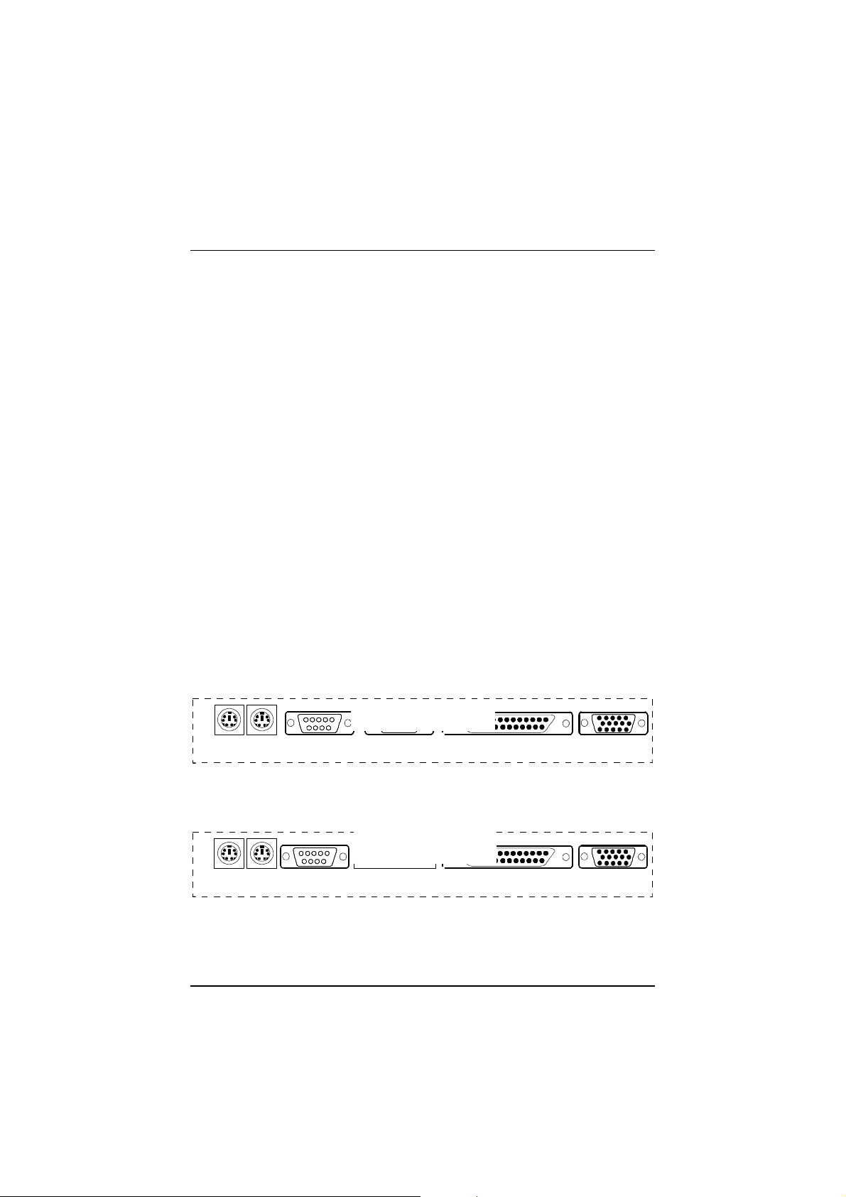
I/O Connector With Onboard COM1 and COM2 Ports
PS/2
Mouse
PS/2
KeyboardCOM2PrinterVGACOM1
[I/O ConnectorPhoto]
A
I/O Connector With Onboard USB Port
PS/2
Mouse
PS/2
KeyboardUSB PrinterVGACOM1
[
I
/
O
C
o
n
n
e
c
t
o
r
P
h
o
t
o
]
B

PAK-2005 Mainboard Manual
12
— This Page Intentionally Left Blank —

13
Chapter 2
Installation Procedures
The PAK-2005 has several user-adjustable jumpers on the board that allow you to
configure your system to suit your requirements. This chapter contains information
on the various jumper settings on your mainboard.
Before using the computer, you must complete the following steps:
nStep 1 -
Set system jumpers
nStep 2 -
Install system RAM modules
nStep 3 -
Install the Central Processing Unit (CPU)
nStep 4 -
Install expansion cards
nStep 5 -
Connect ribbon cables, cabinet wires, and power supply
nStep 6 -
Set up BIOS software (Please read Chapter Three)
WARNING: Excessive torque may damage the mainboard. When using an
electric screwdriver on the mainboard, make sure that the torque
is set to the allowable range of 5.0 ~ 8.0kg/cm.
Mainboard and components contain very delicate Integrated
Circuit (IC) chips. To prevent static electricity from harming any of
the mainboard’s sensitive components, you should follow some
precautions whenever working on the computer:
1. Unplug the computer when working on the inside.
2. Hold components by the edges and try not to touch the IC
chips, leads, or circuitry.
3. Wear an anti-static wrist strap which fits around the wrist.
4. Place components on a grounded anti-static pad or on the bag
that came with the component whenever the components are
separated from the system.
Table of contents
Other FIC Motherboard manuals


