Maxtang WL35 User manual

WL-35 Disk Size Motherboard

Copyright
© 2021 Shenzhen Maxtang Computer Co., Ltd. All rights reserved. No part of this publication may be
reproduced, copied, stored in a retrieval system, translated into any language or transmitted in any
form or by any means, electronic, mechanical, photocopying, or otherwise, without the prior written
consent of Shenzhen Maxtang Computer Co., Ltd (hereinafter referred to as “Maxtang”).
Disclaimer
Maxtang reserves the right to make changes and improvements to the products described in this
document without prior notice. Every effort has been made to ensure the information in the document
is correct; however, Maxtang does not guarantee this document is error-free.
Maxtang assumes no liability for incidental or consequential damages arising from misapplication or
inability to use the product or the information contained herein, nor for any infringements of rights of
third parties, which may result from its use.
Trademarks
All the trademarks, registrations, and brands mentioned herein are used for identification purposes only
and may be trademarks and/or registered trademarks of their respective owners.

Shenzhen Maxtang Computer Co., Ltd
1
WL35 Motherboard
User Manual
(Version 1.0)
Version:
NO.
Description
Issue Date:
V1.0
Initial version (EN)
2021/4/9
Updated to support 12V/19V DC-in power supply
2021/10/28

Shenzhen Maxtang Computer Co., Ltd
2
Contents
Chapter 1 Product Introduction.................................................................................................................................... 3
1.1 Brief Introduction....................................................................................................................................... 3
1.2 Parameters ................................................................................................................................................. 3
1.3 Connector Diagram .................................................................................................................................... 4
Chapter 2 Hardware................................................................................................. 5
2.1 Jumper Setting ........................................................................................................................................... 5
2.2 Memory Slots ............................................................................................................................................. 5
2.3 Display Interfaces ....................................................................................................................................... 5
2.4 Expansion (screen printing: M.2_E) ........................................................................................................... 5
2.5 Storage (screen printing: M.2_S/W, SATA, PWSATA) .................................................................................. 5
2.6 USB Interface.............................................................................................................................................. 6
2.7 LAN............................................................................................................................................................. 6
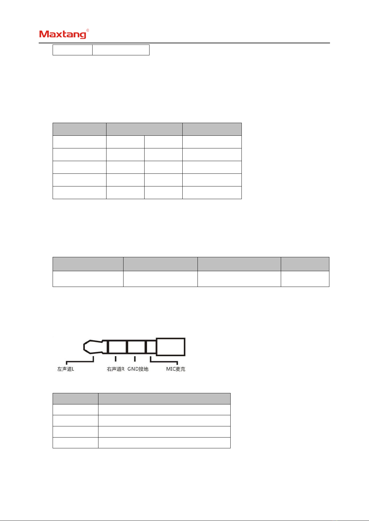
2.8 Audio Interface........................................................................................................................................... 6
2.9 COM ........................................................................................................................................................... 7
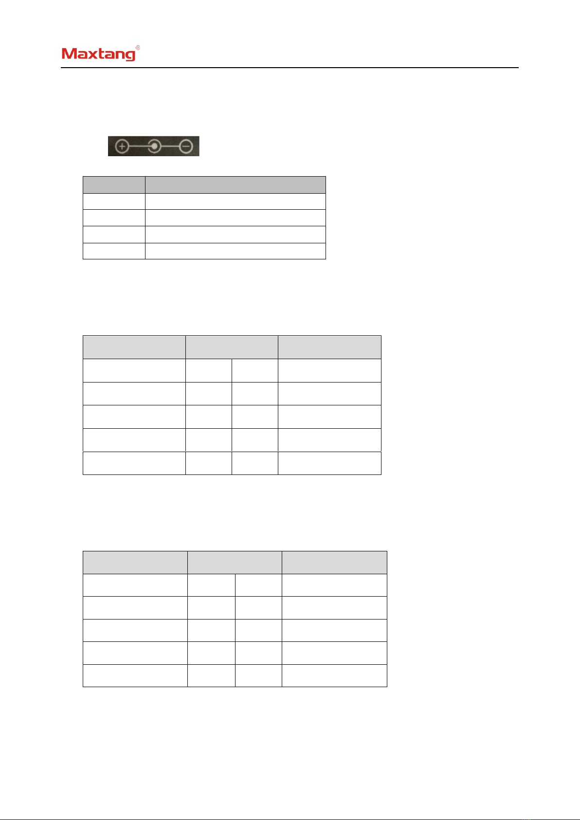
2.10 Power Supply (screen printing: PWR1, PWR2)......................................................................................... 8
2.11 GPIO (screen printing: GPIO).................................................................................................................... 8
2.12 LPC (Optional) .......................................................................................................................................... 8
2.13 Switch Button/Indicator Pin (screen printing: JPOWER) .......................................................................... 8
2.14 CPU FAN Socket (screen printing: CPU_FAN) ........................................................................................... 9
2.15 CMOS Clearance/Retention (screen printing: JCMOS) ............................................................................. 9

Shenzhen Maxtang Computer Co., Ltd
3
Chapter 1 Product Introduction
1.1 Brief Introduction
The WL35 motherboard is a 3.5" SBC (Single Board Computer) based on the Intel Whiskey Lake-U platform,
small formed with low power consumption and high performance.
1.2 Parameters
CPU:
⚫Intel Core i7-8565U — Quad Core Eight Threads, Base Frequency 1.8GHz, Turbo Frequency 4.6GHz, TDP 15W
⚫Intel Core i5-8365U — Dual Core Eight Threads, Base Frequency 1.6GHz, Turbo Frequency 3.9GHz, TDP 15W
⚫Intel Core i3-8145U — Dual Core Four Threads, Base Frequency 2.1GHz, Turbo Frequency 3.9GHz, TDP 15W
⚫Intel Celeron 4205U — Dual-Core Two Threads, Base Frequency 1.8GHz, TDP 15W
Memory: Supports Dual Channel SO-DIMM DDR4, up to 64GB
GPU: Integrated Graphics based on CPU, Display via 1x HDMI,1x DP,1x eDP
Storage: 1 x M.2 Key B for 2242 SSD (SATA Definition) /4G Module, 1x SATA3.0
USB: 4xUSB3.1 Gen2, 2xUSB2.0
Ethernet: 2xGigabyte Network Controllers (1x Intel i211, 1x Intel i219)
Audio: High-definition audio chip, supports Speaker-out, Mic-in, and power amplifier functions
Other I/O: 1xM.2 Key E (Type 2230, for Wi-Fi card and Bluetooth),1 set of LPC, 1 set of GPIO, 4xRS232, 2xRS485
Dimension: 146mm x 102mm (3.5")
Power: 12V/19V DC-in
Working Temperature: -20℃~60℃

Shenzhen Maxtang Computer Co., Ltd
4
1.3 Connector Diagram
DC_IN
PWR2
USB3.0
USB3.0
LAN1
LAN2
HDMI+DP
AUDIO
JAUD
COM14
JPOWER
EDP
GPIO
COM56
LPC
USB2.0
M.2_WIFI
M.2_SSD/4G
PWSATA
SATA
CPU_FAN
SO-DIMM
CPU
SIM

Shenzhen Maxtang Computer Co., Ltd
5
Chapter 2 Hardware
2.1 Jumper Setting
Please configure the jumpers according to your requirements before installing the hardware.
How to identify the first header of jumpers and pins: Observe the mark beside the jumper or pins and
find the header marked by “1” or bold line or triangular symbol. Or observe the rear panel and the header
with a square solder pad is the first header.
2.2 Memory Slots
On-board 2 x SO-DIMM DDR4 slots, supporting dual channels, maximum capacity 64 GB.
2.3 Display Interfaces
1x HDMI (1.4) standard interface.
1x DP (1.2) interface.
1x eDP (1.3) interface, the screen power supply LCD_VCC defaults to 3.3V, and BL_PWR defaults to 12V.
(Note: the backlight output voltage is the same as the power input voltage)
eDP (screen printing: EDP)
Signal
Pin
Pin
Pin
Pin
Signal
GND
1
2
GND
LINE1_N
3
4
LINE1_P
LINE0_N
5
6
LINE_P
AUX_N
7
8
AUX_P
GND
9
10
GND
SMB_CLK
11
12
SMB_DAT
HPD
13
14
LCD_VCC
BL_EN
15
16
BL_PWM
GND
17
18
GND
BL_PWR
19
20
BL_PWR
2.4 Expansion (screen printing: M.2_E)
Screen printing M.2_E: M.2 slots Key E, Supports 2230 WIFI Card with Bluetooth functions.
2.5 Storage (screen printing: M.2_S/W, SATA, PWSATA)
Screen printing M.2_S/W: M.2 slot Key B, supports 2242 SATA protocol SSD/4G module, and has a Micro
SIM card slot; supports 1xSATA3.0, provides 1xPWSATA hard disk power supply socket (only supports 2.5-inch
disks).
PWSATA (screen printing: PWSATA)
Pin
Signal
1
5V
2
GND
3
GND

Shenzhen Maxtang Computer Co., Ltd
6
4
NC
2.6 USB Interface
4 standard USB3.1 Gen2, 2 built-in USB2.0 interfaces (2.0mm pitch pins).
The USB3.1 Gen2 rear ports are powered by 5V Standby voltage, which could also supply power to
external devices when it is turned off (not when they were powered off): 5V/1A.
USB2.0 Pin (screen printing: USB2.0)
Signal
Pin
Signal
VCC 5V
1
2
VCC 5V
USB DATA-
3
4
USB DATA-
USB DATA+
5
6
USB DATA+
GND
7
8
GND
NC
9
10
(N/A)
2.7 LAN
The board provides two high-performance RJ45 interfaces, installed Intel Gigabit Ethernet i219 (LAN1)
and i211 (LAN2) controllers, supports Magic packet wake-up.
The LAN2 (i211) also supports PXE network boot.
LED Status Indicators:
LI_LED Status (Green)
Function
ACT_LED Status (Orange)
Function
Always on
Network Connected
Blinking
Data transfer
2.8 Audio Interface
Realtek HD audio chip equipped, provides a 3.5mm Line-out/MIC 2 in 1 combo jack (CTIA American
standard), and a built-in dual-channel power amplifier output socket for connecting passive speakers.
Two-in-one headphone jack:
JAUD (screen printing: JAUD)
Pin
Signal
1
L+
2
L-
3
R-
4
R+

Shenzhen Maxtang Computer Co., Ltd
7
2.9 COM
The board provides 4x RS232 and 2xRS485 on-board COM header (2.0mm spacing). The RS232 serial
ports are electrified, their voltage is the same as the input voltage of the board.
RS232 (screen printing: COM14)
Signal
Pin
Signal
DCD#
1
2
RXD
TXD
3
4
DTR#
GND
5
6
DSR#
RTS#
7
8
CTS#
RI#
9
10
VCC (same as the input voltage of the board)
DCD#
11
12
RXD
TXD
13
14
DTR#
GND
15
16
DSR#
RTS#
17
18
CTS#
RI#
19
20
VCC (same as the input voltage of the board)
DCD#
21
22
RXD
TXD
23
24
DTR#
GND
25
26
DSR#
RTS#
27
28
CTS#
RI#
29
30
VCC (same as the input voltage of the board)
DCD#
31
32
RXD
TXD
33
34
DTR#
GND
35
36
DSR#
RTS#
37
38
CTS#
RI#
39
40
VCC (same as the input voltage of the board)
RS485 (screen printing: COM5_6)
Signal
Pin
Signal
COM5_DATA-
1
2
COM6_DATA-
COM5_DATA+
3
4
COM6_DATA+
GND
5
6
GND

Shenzhen Maxtang Computer Co., Ltd
8
2.10 Power Supply (screen printing: PWR1, PWR2)
The board supports 12V/19V DC-in power supply.
PWR1:
PWR2 (screen printing: PWR2)
Pin
Signal
1
VIN
2
VIN
3
GND
4
GND
2.11 GPIO (screen printing: GPIO)
The board is equipped with a set of JGPIO 2x5Pin (2.0mm spacing), supports 8 programmable I/O lanes in
total.
GPIO (screen printing: GPIO)
Signal
Pin
Signal
SIO_GP70
1
2
3.3V
SIO_GP71
3
4
SIO_GP74
SIO_GP72
5
6
SIO_GP75
SIO_GP73
7
8
SIO_GP76
GND
9
10
SIO_GP77
2.12 LPC (Optional)
The board provides a set of LPC pins (2.0mm spacing. Low Pin Count Interface) for connecting external
LPC devices as an optional feature.
LPC (screen printing: LPC)
Signal
Pin
Signal
L_FRAME_N
1
2
LPC_AD3
LPC_AD2
3
4
LPC_AD1
LPC_AD0
5
6
GND
PLTRST
7
8
CLK_LPC
3.3V
9
10
SERIRQ
2.13 Switch Button/Indicator Pin (screen printing: JPOWER)
A set of 2.0mm spacing pins that can be connected to a switch button, a system reset button, a hard disk

Shenzhen Maxtang Computer Co., Ltd
9
read/write indicator, a power-on indicator.
In addition, there was a hard disk read/write indicator (red) and a power-on indicator (blue) on board on
the rear IO panel.
JPOWER (screen printing: JPOWER)
Signal
Pin
Signal
HDD_LED+
1
2
PWR_LED+
HDD_LED-
3
4
PWR_LED-
RSTBTN-
5
6
PWR_ON+
RSTBTN+
7
8
PWR_ON-
NC
9
10
(N/A)
2.14 CPU FAN Socket (screen printing: CPU_FAN)
The board provides a CPU cooling fan socket for better cooling and heat dissipation.
CPU_FAN:
Pin
Signal
1
VCC (default 5V power supply (12V Optional)
2
GND
3
CPUFAN_TAC
4
CPUFAN_CTL
2.15 CMOS Clearance/Retention (screen printing: JCMOS)
CMOS is powered by onboard button batteries. Clearing CMOS will permanently remove the previous
system settings and restore the board system to original settings (factory settings).
Step 1: Turn off the PC and disconnect the power adapter.
Step 2: Press JCMOS for 10 seconds and disconnect.
Step 3: Restart the device, press the <DEL> button to enter the BIOS, load the optimal default value,
save, and exit the settings.
Please do not clear COMS when the PC is connected to power in case board damages.
Other manuals for WL35
1
Table of contents
Other Maxtang Motherboard manuals

Maxtang
Maxtang WL10 User manual

Maxtang
Maxtang BYT60 User manual

Maxtang
Maxtang EHL-10 User manual

Maxtang
Maxtang EHL-10 User manual

Maxtang
Maxtang SKD70 User manual

Maxtang
Maxtang BYT-35 User manual

Maxtang
Maxtang MITX-BYT70 User manual

Maxtang
Maxtang BYT60 User manual

Maxtang
Maxtang AL-10 User manual

Maxtang
Maxtang JSL-15 User manual

Maxtang
Maxtang FP50 User manual

Maxtang
Maxtang TL10 User manual

Maxtang
Maxtang MITX-KL10 User manual

Maxtang
Maxtang APL-35 User manual

Maxtang
Maxtang EHL-35 User manual

Maxtang
Maxtang SKD70 User manual

Maxtang
Maxtang ALN50 User manual

Maxtang
Maxtang DTJ6412-I User manual

Maxtang
Maxtang FP20 User manual

Maxtang
Maxtang BW-35 User manual