manuals.online logo
Brands
  1. Home
  2. •
  3. Brands
  4. •
  5. Edelbrock
  6. •
  7. Automobile Part
  8. •
  9. Edelbrock 68952 User manual

Edelbrock 68952 User manual

Catalog #s 68952, 68953, 68972, 68973
©2006 Edelbrock Corporation Page 1 of 3
Brochure #63-68952
Rev. 5/06 - DA/mc
®
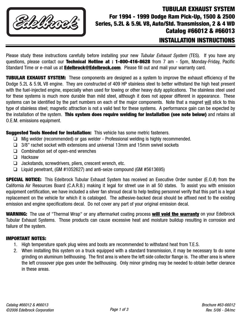
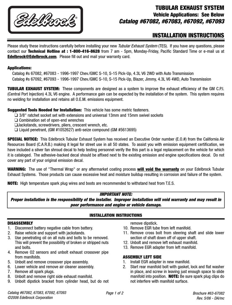
TUBULAR EXHAUST SYSTEM
Vehicle Applications: See Below
Catalog #68952, #68953
#68972, #68973
INSTALLATION INSTRUCTIONS
Please study these instructions carefully before installing your new
Tubular Exhaust System
(TES). If you have any
questions, please contact our Technical Hotline at : 1-800-416-8628 from 7 am - 5pm, Monday-Friday, Pacific
Standard Time or e-mail us at [email protected]. Please fill out and mail your warranty card.
TUBULAR EXHAUST SYSTEM: These components are designed as a system to improve the exhaust efficiency of the GM
2.8L T.B.I. 60-degree V6 engines. A performance gain can be expected by the installation of the system. This system does
not require welding for installation and retains all O.E.M. emissions equipment.
APPLICATIONS:
Catalog #s 68952 / 68953 - 1986-1993 Blazer S-10 & Jimmy S-15, 2.8L 60-degree V6, 2 WD, Standard & Auto
Transmission with A.I.R. & 2-1/4” inlet catalytic
Catalog #s 68972 / 68973 - 1986-1993 S-10 & GMC S-15, 2.8L 60-degree V6, 4 WD, Standard & Auto
Transmission with A.I.R. & 2-1/4” inlet catalytic
Suggested Tools Needed for Installation: This vehicle has some metric fasteners.
❑ 3/8” ratchet socket set with extensions and universal 13mm and 15mm swivel sockets
❑Combination set of open-end wrenches
❑ Jackstands, screwdrivers, pliers, crescent wrench, etc.
❑ Liquid penetrant (GM #1052627), anti-seize compound (GM #5613695)
NOTE: Some models will require a special power steering pulley puller; K-D 2897 or equivalent.
SPECIAL NOTICE: This Edelbrock Tubular Exhaust System has received an Executive Order number (E.O.#) from the
California Air Resources Board (C.A.R.B.) making it legal for street use in all 50 states. To assist you with emission
equipment certification, we have included a silver fan shroud decal to help testing personnel verify the this part is a legal
replacement on the vehicle for which it is cataloged. The adhesive-backed decal should be affixed next to the existing
emission and engine specifications decal. Do not cover any part of your original emission decal.
WARNING: The use of "Thermal Wrap" or any aftermarket coating process will void the warranty on your Edelbrock
Tubular Exhaust Systems. Those products can cause excessive heat and moisture buildup resulting in corrosion and
failure of the system.
NOTE: High temperature spark plug wires and boots are recommended to withstand heat from T.E.S.
IMPORTANT NOTE:
Proper installation is the responsibility of the installer. Improper installation will void warranty and may
result in poor performance and engine or vehicle damage.
Catalog #s 68952, 68953, 68972, 68973
©2006 Edelbrock Corporation Page 2 of 3
Brochure #63-68952
Rev. 5/06 - DA/mc
DISASSEMBLY
1. Disconnect battery negative cable from battery.
2. Raise vehicle and support with jackstands.
3. Use penetrating oil on all nuts and bolts to be
removed. This will prevent the possibility of broken
or stripped nuts and bolts.
4. Making sure the converter is cool, remove the
exhaust crossover pipe.
5. Remove O2 sensor being careful not to rupture or
destroy the unit. WARNING: Do not clean this unit
in any cleaning solvents and do not rupture wire.
6. Remove crossover exhaust pipe.
Left Side -- Remove bolts on left side exhaust
manifold, and remove from top side.
Right Side -- Disconnect A.I.R. or Air Injector
Reactor from A.I.R. manifold at clamped hose.
Remove A.I.R. manifold from exhaust manifold if your
vehicle has air conditioning. At this point, remove
alternator and ignition coil bracket assembly.
Remove bolts on right side of the exhaust manifold
and remove top side. If vehicle is equipped with
power steering, remove rear power steering pump
support bracket. Remove oil dipstick tube. Clean
and inspect all surfaces before assembly.
ASSEMBLY LEFT SIDE
1. Install tubular exhaust manifold on vehicle from top
side with gasket and six 8mm bolts (supplied).
2. Install dipstick tube and dipstick.
3. Install oil pressure sending unit, oil filter and rear
power steering support bracket if applicable.
4. Install O2 sensor. Use anti-seize on threads of
sensor and torque to 30 ft./lbs.
5. Re-route O2 sensor wire from wire loom to O2
sensor pigtail connector, making sure all wires are
clear of exhaust system. An O2 sensor wire
extension is provided if necessary.
6. Install rear power steering pump support bracket.
Use two 11/16" spacers provided to space out
bracket.
INSTALLATION INSTRUCTIONS
ASSEMBLY RIGHT SIDE
1. Install tubular exhaust manifold from top side with
gasket and six 8mm bolts (supplied)
2. Install A.I.R. manifold to tubular exhaust manifold
with spacer supplied and original stud bolt.
3. Connect A.I.R. hose and hose clamp.
4. If equipped with air conditioning, install ignition coil
bracket assembly and alternator. Use 13/16" spacer
provided to space out alternator bracket.
CROSSOVER PIPE ASSEMBLY
1. Assemble both lower pipes. Do not clamp tight at
this point.
2. Install crossover pipe assembly on vehicle with four
3/8” bolts, lock and flat washers and gaskets
supplied. Do not tighten at this time.
CATALYTIC CONVERTER
1. Install converter on crossover pipe assembly.
TIGHTENING SEQUENCE
1. Tighten converter support bracket bolts.
2. Align right side crossover flange with tubular exhaust
flange and tighten.
3. Align left side crossover flange with tubular exhaust
flange and tighten.
4. Install muffler-type clamp on crossover pipe slip joint
and tighten clamp.
5. Tighten catalytic converter.
6. Be sure all brake and fuel lines have adequate
clearance.
LOWER VEHICLE TO THE GROUND
1. Connect negative cable to battery. At this point, it
would be a good idea to look everything over and
make sure nothing is missed in assembly.
2. Start vehicle, bring up to normal operating
temperature and check for possible leaks.
3. Turn engine off and let cool, then tighten all bolts
again.
Catalog #s 68952, 68953, 68972, 68973
©2006 Edelbrock Corporation Page 3 of 3
Brochure #63-68952
Rev. 5/06 - DA/mc
Qty. PN Description
❑ 1 25-9513 Left side crossover extension
❑ 1 25-9517 Left side crossover extension
❑ 1 25-9515 Right side crossover extension
❑ 2 - Cylinder head exhaust flange gaskets
❑ 2 - Crossover flange donut gaskets
❑ 1 - Muffler-type clamp assembly; 2”
❑ 12 - Bolts; 8mm x 20mm
❑ 4 - Cap screws; 2” x 3/8” x 16
❑ 12 - Lock washers; 5/16”
❑ 4 - Flat washers; 3/8”
❑ 4 - Lock washers; 3/8”
❑ 1 - O2 Sensor extension; 36”
❑ 1 - Spacer tube; 2”
❑ 2 - Spacer tubes; 1/2” x 11/16”
❑ 1 - Spacer tube; 1/2” x 13/16”
❑ 1 - Flange connector
❑ 3 - AN Flat washer; 5/16”
Qty. PN Description
❑125-9426 Header left side (#68952)
❑125-9425 Header right side (#68952)
❑125-9015 Header left side (#68953)
❑125-9016 Header right side (#68953)
KIT CONTENTS
Catalog #68952, Catalog #68953 (Ti-Tech Coated)
Edelbrock Corporation, 2700 California St., Torrance, CA 90503
Tech Line: 1-800-416-8628
E-Mail: [email protected]
Qty. PN Description
❑1 25-9427 Header left side (#68972)
❑1 25-9425 Header right side (#68972)
❑ 1 25-9017 Header left side (#68973)
❑ 1 25-9016 Header right side (#68973)
KIT CONTENTS
Catalog #68972, Catalog #68973 (Ti-Tech Coated)
KIT CONTENTS
Common to All Part Numbers

This manual suits for next models

3

Other Edelbrock Automobile Part manuals

Edelbrock 3581 User manual

Edelbrock

Edelbrock 3581 User manual

Edelbrock 2886 User manual

Edelbrock

Edelbrock 2886 User manual

Edelbrock 1931 User manual

Edelbrock

Edelbrock 1931 User manual

Edelbrock 5658 User manual

Edelbrock

Edelbrock 5658 User manual

Edelbrock For 1985-1992 GM Cars and Trucks 17933 User manual

Edelbrock

Edelbrock For 1985-1992 GM Cars and Trucks 17933 User manual

Edelbrock 67312 User manual

Edelbrock

Edelbrock 67312 User manual

Edelbrock 70405 User manual

Edelbrock

Edelbrock 70405 User manual

Edelbrock 5420 User manual

Edelbrock

Edelbrock 5420 User manual

Edelbrock 72000 User manual

Edelbrock

Edelbrock 72000 User manual

Edelbrock 6571 User manual

Edelbrock

Edelbrock 6571 User manual

Edelbrock 1403-1413 User manual

Edelbrock

Edelbrock 1403-1413 User manual

Edelbrock 67082 User manual

Edelbrock

Edelbrock 67082 User manual

Edelbrock 15015 User manual

Edelbrock

Edelbrock 15015 User manual

Edelbrock Performer Multipoint 3501 Technical document

Edelbrock

Edelbrock Performer Multipoint 3501 Technical document

Edelbrock 440 User manual

Edelbrock

Edelbrock 440 User manual

Edelbrock Victor Jr. 289-302 User manual

Edelbrock

Edelbrock Victor Jr. 289-302 User manual

Edelbrock 2103 Instruction manual

Edelbrock

Edelbrock 2103 Instruction manual

Edelbrock 5486 User manual

Edelbrock

Edelbrock 5486 User manual

Edelbrock 4803 User manual

Edelbrock

Edelbrock 4803 User manual

Edelbrock 4737 User manual

Edelbrock

Edelbrock 4737 User manual

Edelbrock E-Force 1580 User manual

Edelbrock

Edelbrock E-Force 1580 User manual

Edelbrock Later Harley-Davidson 1604 User manual

Edelbrock

Edelbrock Later Harley-Davidson 1604 User manual

Edelbrock 2005-2007 (R) User manual

Edelbrock

Edelbrock 2005-2007 (R) User manual

Edelbrock 460 Ford User manual

Edelbrock

Edelbrock 460 Ford User manual

Popular Automobile Part manuals by other brands

Aim CF2 Installation instruction

Aim

Aim CF2 Installation instruction

Pacbrake P39106 Installation

Pacbrake

Pacbrake P39106 Installation

Holland Challenger Series Operating Instructions & Maintenance Procedures

Holland

Holland Challenger Series Operating Instructions & Maintenance Procedures

AUTOTECH 10.297.210K-214K installation instructions

AUTOTECH

AUTOTECH 10.297.210K-214K installation instructions

Network Computing Devices 2190 installation instructions

Network Computing Devices

Network Computing Devices 2190 installation instructions

Bestop 29283 installation instructions

Bestop

Bestop 29283 installation instructions

Skyjacker C720MS installation instructions

Skyjacker

Skyjacker C720MS installation instructions

bosal 037031 Fitting instructions

bosal

bosal 037031 Fitting instructions

Munters MWI Series Quick assembly guide

Munters

Munters MWI Series Quick assembly guide

Central Hydraulics 54877 Assembly and operating instructions

Central Hydraulics

Central Hydraulics 54877 Assembly and operating instructions

Mitsubishi F5M41 manual 

Mitsubishi

Mitsubishi F5M41 manual 

QA1 GS501 installation instructions

QA1

QA1 GS501 installation instructions

aFe Power 50-70046R instruction manual

aFe Power

aFe Power 50-70046R instruction manual

Active E36 installation instructions

Active

Active E36 installation instructions

Emerson ATEX reference guide

Emerson

Emerson ATEX reference guide

Harbor Freight Tools Nitrous 98480 Instructions and precautions

Harbor Freight Tools

Harbor Freight Tools Nitrous 98480 Instructions and precautions

Flowmaster 814110 installation instructions

Flowmaster

Flowmaster 814110 installation instructions

Yoshimura 03-09 SUZUKI LT-Z400 Installation procedures

Yoshimura

Yoshimura 03-09 SUZUKI LT-Z400 Installation procedures

manuals.online logo
manuals.online logoBrands
  • About & Mission
  • Contact us
  • Privacy Policy
  • Terms and Conditions

Copyright 2025 Manuals.Online. All Rights Reserved.