EDI DSTS-5A User manual

DSTS-5A User's Manual
1. PACKING LIST
2. OVERVIE
3. CONNECTING THE DSTS-5A TO A COMPUTER
4. CONNECTING A DEPTH SOUNDER TO THE DSTS-5A
5. OPERATING THE DSTS-5A
6. CALIBRATING THE DSTS-5A
7. SOFT ARE UPDATES
8. INSTALLING A CUSTOM LOAD
9. DSTS-5A SPECIFICATIONS
10. ARRANTY INFORMATION
DSTS-5A Manual Page 1 Rev 140930-300
DSTS-5A User's Manual
1 PACKING LIST
1.1 The following items a e included with the DSTS-5A:
1.1.1 Powe t ansfo me . A 9VDC 300mA wall plug powe adapte is supplied.
Nominal powe equi ements a e 8 to 12 volts at 200 mA.
1.1.2 A CD with softwa e fo cont olling, calib ating, and updating the DSTS-4A.
1.1.3 A use 's manual.
2 OVERVIEW
2.1 The DSTS-5A is a compute cont olled depth sounde test set with fish echo emulation.
All functions such as eply level, depth, and width fo the fish and bottom echoes a e
cont olled by data sent th ough the RS-232 po t. The included p og am “DSTS-5A
Vx.xx.exe” o any te minal p og am may be used to cont ol the DSTS-5A.
2.2 OPERATING THE DSTS-5A WITHOUT A COMPUTER
2.2.1 When powe ed up without the RS-232 connection the DSTS-5A will ope ate in
the Q-mode, allowing a depth sounde to be evaluated based on the t ansmitte
powe and eceive sensitivity. The Q-mode gene ates an echo based on
t ansmitted powe and depth. The depth is inc emented by one foot and the eply
level is dec eased each time the depth sounde t ansmits a pulse. As the depth
inc eases a point will be eached whe e the echo is no longe eceived. The quality
of the depth sounde can be ead f om the maximum depth eading befo e the echo
is lost.
3 CONNECTING THE DSTS-5A TO A COMPUTER
3.1 To install the supplied softwa e, copy the file “DSTS-5A Vx.xx.exe”to a di ecto y of
you choice. To un the
p og am, click on it and it
will launch. You must have a
se ial po t o USB/se ial
adapte to use this p og am.
3.2 Connect the DSTS-5A to the
compute using a standa d 9
pin RS-232 cable. Connect
the wall t ansfo me powe
supply. Status LED 2 will
light fo six seconds and the
status LED's will sequence
one time. Afte powe -up the
status LED 3 will glow and
pulse at a one-second ate indicating the DSTS-5A is eady fo ope ation.
DSTS-5A Manual Page 2 Rev 140930-300

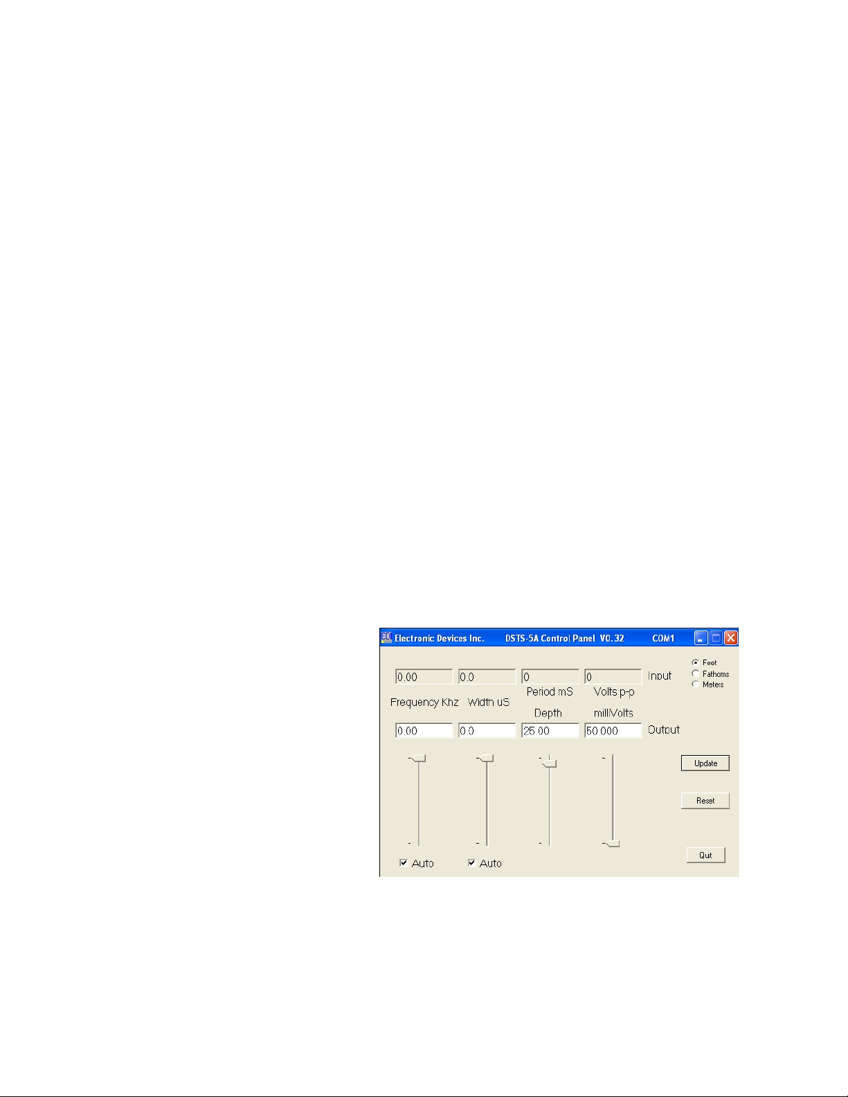
3.3 Run the “DSTS-5A Vxxx.exe” p og am. If the com po t and RS-232 connection a e
co ect, The DSTS-5A cont ol panel p og am will open as shown. The input
f equency, width, pe iod, and amplitude display ze o until a pulse is eceived f om the
depth sounde . To ve ify the connection, click the “ eset” button. If the connection is
good, the softwa e ve sion will appea b iefly in the input f equency display box.
4 CONNECTING A DEPTH SOUNDER TO THE DSTS-5A
4.1 Connect a depth sounde to the IN/OUT connecto . Do not connect depth
sounder to the Trig Out connector or the DSTS-5A will be damaged. If the
depth sounde has a balanced output, one of the two inne wi es will need to be
connected to the shield and g ounded. Consult the manufacturers manual to determine
if one wire and the shield can be used as ground without damaging the depth sounder.
If you a e unsu e of the co ect
connections fo a balanced output,
use the EDI BAL-550 accesso y.
The BAL-550 is a balanced-to-
unbalanced t ansfo me that has
connections fo the shield and two
wi es. The output of the BAL-550
connects to the DSTS-5A.
4.1.1 Apply powe to the depth
sounde . When the sounde
t ansmits, the ed status LED
will blink indicating that a
pulse has been eceived.
4.1.2 The input cha acte istics of the eceived pulse a e displayed on the uppe g oup
of boxes and t ansmitted echo signals a e displayed in the lowe g oup. The esults
a e updated each time the DSTS-5A eceives a pulse o once a second if no pulse
has been eceived. If the depth sounde is disconnected, the input pulse
cha acte istics will still display and will not change until a new pulse is eceived.
P essing the “ eset” button will eset the DSTS-5A and clea the input g oup of
displays.
5 OPERATING THE DSTS-5A
5.1 SETTING THE DEPTH AND REPLY LEVEL
The depth and eply level a e set using the two t ack ba s on the ight side. Use the
mouse to move the slide to the desi ed depth. Fine adjustments a e made using the
keyboa d up and down a ow keys. Fo best esults move the slide slowly.
5.2 SETTING THE FREQUENCY
5.2.1 Click the “Auto” button below the f equency t ack-ba to put the DSTS-5A in the
manual f equency mode. The check ma k will disappea indicating that the DSTS
is in the manual f equency mode. Use the mouse to move the slide to the desi ed
f equency. Fine adjustments a e made using keyboa d up and down a ow keys.
DSTS-5A Manual Page 3 Rev 140930-300

5.3 SETTING THE WIDTH
5.3.1 Click the “Auto” button below the f equency t ack-ba to put the DSTS-5A in the
manual width mode. The check ma k will disappea indicating that the DSTS is in
the manual width mode. Use the mouse to move the slide to the desi ed f equency.
Fine adjustments a e made using keyboa d up and down a ow keys.
5.4 RESTORING THE AUTO TRACK MODES
5.4.1 To put the DSTS-5A into the t acking f equency mode, click the “Auto” button
to esto e the check ma k. The DSTS-5A will then gene ate eply pulses with the
same f equency as the input pulse.
5.4.1.1 Note: Always use the auto-f equency mode when using a dual-f equency
sounde .
5.4.2 To put the DSTS-5A in the pulse width t acking mode, click the “Auto” button to
esto e the check ma k. The DSTS-5A will gene ate eply pulses that a e 1.6 times
wide than the input pulse width.
5.4.2.1 Note: Some depth sounde s equi e that the auto-width mode is on
(checked) to ope ate co ectly.
5.5 USING A TERMINAL PROGRAM WITH THE DSTS-5A TO ACCESS
ADDITIONAL FUNCTIONS
5.5.1 The DSTS-5A can be used with the supplied te minal p og am,
DSTS_te minal.exe. To sta t the EDI DSTS-5A Te minal P og am, un the file
DSTS_te minal.exe any supply the active com po t when equested. If using a
diffe ent te minal p og am o Window's Hype Te minal the pa amete s should be
set fo 9600 Baud, 8-bit data, no pa ity, one stop-bit. Flow cont ol should be set to
none.
DSTS-5A Manual Page 4 Rev 140930-300

5.5.1.1 The e a e two modes of ope ation fo the DSTS-5A, the -4A mode and the
-5A mode.
5.5.1.1.1 The -5A mode is used with the supplied Window's p og am and can
also be cont olled f om any te minal p og am by sending the commands
detailed in the “Command List fo -5A Mode”.
5.5.1.1.2 The -4A mode emulates a DSTS-4A with the EAB-3 option and is
only intended fo use by custome s who a e cu ently using the DSTS-
4A/EAB-3 in p oduction test.
5.6 The velocity of p opagation fo a new unit is set to 4800 feet pe second and 1500
mete s pe second. These values a e sto ed in eep om and may be changed if desi ed.
5.6.1 Fo met ic calib ation fi st choose the met ic mode by typing “cm”followed by
'ente '. Then type a lowe case 'v' followed by the desi ed Vp op in mete s/sec. Fo
example, to set Vp op to 1502 mete s/ second type “v1502” and 'ente '.
5.6.2 Fo setting Vp op in feet fi st choose the foot mode by typing “cf”followed by
'ente '. Then type a lowe case 'v' followed by the desi ed Vp op in mete s/sec. Fo
example, to set Vp op to 4915 feet/second type “v4915” and 'ente '.
5.6.2.1 FISH ECHO GENERATION
5.6.2.1.1 The DSTS-5A is capable of gene ating a seconda y echo between the
su face and bottom. This echo can be used to simulate an echo f om a fish
o othe object above the bottom and will be efe ed to as a fish echo. The
depth, width, amplitude, du ation and a ch shape of the fish echo can be
set. The du ation of the fish echo is set by specifying the numbe of echoes
that the fish will gene ate as it passes unde the t ansduce . A mo e ealistic
fish echo can be gene ated by specifying a depth inc ement. The depth of
the fish echo is dec eased fo half the du ation then inc eased fo the
emainde of the du ation. If the inc ement is set to ze o the fish echo will
emain at a constant depth du ing its du ation.
5.6.2.1.2 SETTING UP A TYPICAL FISH ECHO
5.6.2.1.2.1 Set the bottom depth to 25 feet by typing “d250 'ente '”. Set the
fish depth to 23 feet by typing “D230 'ente '”. Set the fish echo off time
to 20 pulses by typing “e20 'ente '”. Set the fish on time to 3 pulses by
typing “E3 'ente '” and the fish echo will appea fo 3 pulses eve y
twenty pulses and epeat until disabled by typing “e 'ente ”.
5.6.2.1.2.2 The amplitude of the fish echo can be set using the “L”
command.
DSTS-5A Manual Page 5 Rev 140930-300

5.6.2.1.2.3 The width of the fish echo t acks the width of the pulse f om the
depth sounde in the auto-t ack mode. It can be manually set using the
'Wxxxx' command. Fo example, “W200 'ente '”will fix the fish echo
width at 200 uSec.
5.6.2.1.2.4 To make the fish echo stay on continuously type “E 'ente ' ”.
Type “e 'ente ' ” to tu n the fish echo off.
5.6.2.1.2.5 To gene ate a fish a ch use the “i” command to ente an value in
tenths of the selected units ep esenting the a ch height.
5.6.2.1.3 CHIRP ECHO OPERATION
5.6.2.1.3.1 A chi p can be gene ated as a eply fo the fo the bottom echo.
This chi p is a linea f equency vs. time type. Inputs a e the sta t
f equency, f equency step, step size, and the dwell time fo the
f equency step. When the bottom echo occu s, it will sweep f om the
sta t f equency th ough the numbe of steps.
5.6.2.1.3.1.1 The ending f equency will be equal to sta t f equency +
(numbe of steps * step size).
5.6.2.1.3.1.2 The du ation of the chi p will be the numbe of steps *
dwell time. Note that minimum dwell time is about 5 uSec.
5.6.2.1.3.1.2.1 The dwell time is dependent on othe facto s such as
f equency so fo maximum accu acy we ecommend using an
oscilloscope to check the echo du ation.
5.6.2.1.3.2 Ente the chi p menu by typing 'h'. A sub-menu appea s and the
dwell time, sta t f equency, step size, and numbe of steps may be
ente ed. When the desi ed values have been ente ed type uppe case 'X'
to leave the chi p sub-menu and etu n to the -5A command menu so
depth, amplitude, etc. can be set. Note that typing 'X' does not stop the
chi p mode, it only exits the sub-menu.
5.6.2.1.3.3 To stop the chi p echo mode and etu n to no mal ope ation,
type an uppe case 'H'. To e-sta t the chi p type 'h' and the p eviously
ente ed chi p settings will be used. These settings a e not etained when
the powe is tu ned off.
DSTS-5A Manual Page 6 Rev 140930-300

5.6.2.2 DSTS-5A COMMAND LIST
Command List fo -5A Mode
LETTER FUNCTION
a Sets width Auto T ack mode on. Tu ns off when a width is sent to the DSTS.
A Sets f equency Auto T ack mode on. Tu ns off when a f equency sent to the DSTS.
b Sets no mal (pulsed output) mode of ope ation.
B Sets output signal to continuous wave (CW mode).
cf Sets the calib ation to feet.
cF Sets the calib ation to Fathoms.
cm Sets the calib ation to mete s.
dxxxxxx Sets the bottom depth in tenths of the selected units, feet, mete s, o fathoms.
Dxxxxxx Sets the fish depth in tenths of the selected units.
e Tu ns off the fish echo mode. Retu ns only bottom echo.
exx The fish echo will be off fo xx pulses f om the depth sounde .
E Tu ns on the fish echo mode. Retu ns two echoes, fish and bottom.
Exx The fish echo will be on fo xx pulses. Use with exx fo epeating fish.
fxxxxx Sets the eply f equency in 10 Hz units.
Gx Sets eply pulse st etch. X = 0,1,2,3,4 fo 0.8, 1.0, 1.2, 1.4, o 1.6 times input pulse width.
h Ente s the chi p mode sub-menu and sta ts chi p eply.
H Stops the chi p echo mode and etu ns to no mal ope ation.
i Sets the inc ement fo the fish echo a ch in tenths of the selected units.
l Sets the bottom echo eply level in 0.3 dB steps, 0 to 255 max. 255 = 50 mV ms.
L Sets the fish echo eply level in 0.3dB steps, 0 to 255 max. 255 = 50 mV ms.
p Inse ts additional 10 dB attenuation to eply level.
P Removes additional 10 dB attenuation. Default condition.
~~~ Resets the DATA-5A ha dwa e and softwa e.
Resets and e-initializes the f equency ave aging filte .
s Stops auto data t ansmission f om occu ing. Data only sent when 'ente ' is p essed.
S Sta t auto data t ansmission. All input/output pa amete s a e sent.
t Test mode. Steps attenuato , sweeps f equency and voltmete calib ation.
v Sets and sto es the velocity of p opagation in feet o mete s pe second.
wxxxxx Sets the bottom echo width in mic oseconds.
Wxxxxx Sets the fish echo width in mic oseconds.
x Ente s the -4A mode of cont ol.
? Sends a simple menu of all commands to the te minal.
Note: The velocity of p opagation as set in the -5A mode will apply to the -4A mode. The e is no p ovision to
set the velocity of p opagation while ope ating in the -4A mode. Limits to Vp op a e 4000 to 6000 feet/second
and 1000 to 2000 mete s/second.
DSTS-5A Manual Page 7 Rev 140930-300

5.7 OPERATING IN THE -4A MODE
5.7.1 The-4A mode pe fo ms exactly like the DSTS-4A with the EAB-3 option. All
commands a e the same. To ente the -4A mode of ope ation type ‘x’ followed by
the ‘ente ’ key. Once in the -4A mode use the -4A commands. A list of the
commands is attached. In addition typing ‘?’ will b ing up a menu of commands.
5.7.2 Single cha acte commands such as 'A' do not need to be followed by ente .
Multiple cha acte commands such as 'cf' o 'd2345' must be followed by the 'ente '
key.
Command List fo -4A Mode
LETTER FUNCTION
a Sets width Auto T ack mode on. Tu ns off when a width is sent to the DSTS.
A Sets f equency Auto T ack mode on. Tu ns off when a f equency sent to the DSTS.
b Sets no mal (pulsed output) mode of ope ation.
B Sets output signal to continuous wave (CW mode).
C Checks 50 kHz clock f equency.
cf Sets the calib ation to feet.
cF Sets the calib ation to Fathoms.
cm Sets the calib ation to mete s.
cR Extend Depth ange to 9999 FT/FM/MT.
c Reduce Depth ange to 999.9 FT/FM/MT.
dxxxx Sets the bottom depth in tenths of the selected units.
Dxxxx Sets the fish depth in tenth’s of the selected units.
e Tu ns off the fish echo mode. Retu ns one bottom echo.
E Tu ns on the fish echo mode. Retu ns two echoes.
fxxxx Sets the eply f equency in 100 Hz units.
i Retu ns DSTS data on input pulse pa amete s in this o de :
F equency, width, pe iod, P-P voltage.
A typical st ing is 503,192,107,540. Leading 0's a e not sent.
l Sets the eply level in .3 dB steps, 0 to 255 max.
m Retu ns DSTS modes in this o de :
Calib ation 0=ft, 1=fm, 2=mt
Numbe of p ocessed pulses eceived since eset 0-255
Bottom echo o fish with bottom echo bot o fsh
Auto width T ack o manual awt o mwt
Auto f equency T ack o manual aft o mft
CW o pulsed output cwo o pul
Filte settled o not settled. set o nst
A typical st ing is 0,bot,73,awt,aft,pul,set
o Retu ns DSTS data on output pulse pa amete s in this o de :
F equency, width, depth, eply level.
Resets t acking gate and adaptive filte s fo f equency acquisition.
R Resets the DSTS to powe up default mode without exiting RS-232.
v Repo ts the softwa e ve sion.
wxxxxx Sets the bottom echo width in mic oseconds. .
Wxxxxx Sets the fish echo width in mic oseconds.
x Ente s the emote mode of cont ol.
X Exits the emote mode and etu n DSTS to no mal ope ation.
? Sends a simple menu of all commands to the te minal.
DSTS-5A Manual Page 8 Rev 140930-300

6 CALIBRATING THE DSTS-5A
6.1 The load esisto can change if ove heated by too much powe . A la ge change in the
esistance will cause the voltage and eply eadings on a depth sounde to change. The
load esisto should be checked any time abno mal eadings a e expe ienced.
6.1.1 Check the load esistance with the DSTS-5A powe off. Place an ohmmete
ac oss the IN/OUT connecto . The esistance fo the facto y installed load should
be 582 ohms +/- 10%. The esistance of a custom load at the IN/OUT connecto
should ead 22 ohms highe than the value of the installed load esisto . If the load
is out of spec, the unit should be taken apa t and the load esisto eplaced befo e
any fu the calib ation o checks a e done.
6.1.2 Run the supplied te minal p og am, DSTS_te minal.exe.
6.1.3 VOLTMETER CALIBRATION
Caution—Do not perform this procedure without a EDI DSTS calibrator
or other comparable pulse source.1
6.1.3.1 The volt mete calib ation is in the “extended menu”. Type 't' to ente the
extended menu. Then type 'c' to sta t the voltmete calib ation outine. Connect
the EDI DSTS calib ato o othe compa able pulse sou ce to the IN/OUT
connecto . Afte the indicated voltage eadings have settled down, type in the
co ect input pulse voltage in volts peak-to-peak and p ess 'ente '. A calib ation
facto will be gene ated and sto ed in eep om. P ess the eset button and check
that the voltage eads co ectly. If not, epeat the calib ation.
6.1.4 FREQUENCY CHECK
Connect the DSTS-5A to a f equency counte and p ess the eset button. Set the
output to continuous by typing ‘B’ followed by ‘ente ’. Set output level to
maximum by typing l255. Set the f equency to 100 KHz by typing f10000 followed
by ‘ente ’. The f equency counte must ead 100,000Hz +/- 10 Hz.
6.1.5 REPLY AMPLITUDE CHECK
6.1.5.1 Connect a scope (1 megohm input equi ed) di ectly to the IN/OUT
connecto with a sho t (< 3ft) cable. Set the f equency to 100 KHz (f10000) and
the level to maximum (l255). The voltage must ead 140 mV p-p +/- 7 mV p-p.
This is a fixed facto y setting and will not change unless the DSTS-5A has been
damaged by a seve e ove load.
6.1.6 OPTIONAL REPLY ATTENUATOR CHECK
6.1.6.1 Connect the DSTS-5A IN/OUT connecto to a spect um analyze . Set
va ious levels to make su e the attenuato t acks p ope ly. Note that the output
on the analyze will be low because the 50 ohm input impedance of the
spect um analyze loads down the DSTS-5A output. If a high impedance
(>=100,000 ohm) p obe is available, the eadings will be co ect and a level of
1 The EDI DSTS Calib ato p oduces a 400 volt p-p pulse bu st with a f equency of 204.8 KHz, length of 325 uSec,
and a pe iod of 80 mSec. D oop is less than 10 pe cent.
DSTS-5A Manual Page 9 Rev 140930-300

255 will p oduce 50 mV ms. Each dec ease in the level will educe the output
by 0.3 dB. The object is to ve ify that the attenuato is ope ating p ope ly.
The e a e no adjustments.
7 SO TWARE UPDATES
7.1 The DSTS-5A softwa e can be updated via the RS-232 connection. As softwa e
featu es a e added, pe iodic update files may be sent via email. They can be installed
in the DSTS-5A by using the supplied p og am, “p ogdsts.exe”.
7.1.1 Put the p ogdsts.exe, update.bat, and the updated DSTS-5A.hex file in the same
di ecto y. The illust ations assume the p og am and hex file a e in the c:\ di ecto y.
7.1.2 P ess the eset (RST) button on the DSTS-5A and immediately un the update.bat
p og am. Note that afte a RST, status led 2 stays on 5 seconds, then goes off.
You must sta t the update.bat p og am while the status led 2 is on fo the update to
wo k successfully.
7.1.3 If the update is unning successfully you will see the following sc een:
7.1.4 Afte the update, the above sc een will close and the DSTS-5A will begin
ope ating with the new softwa e. It is not necessa y to eset the DSTS-5A afte an
update.
DSTS-5A Manual Page 10 Rev 140930-300

8 INSTALLING A CUSTOM LOAD
8.1 Disassemble the DSTS-5A by fi st
emoving the hex nut f om the
IN/OUT BNC connecto on the f ont
panel. Refe to illust ation 1 and
emove the black plastic oute bezel
on the back panel (the side with the
RS-232 connecto ) by lifting it nea
the cente on the top and sides whe e
the catches a e located. When the
bezel is off hold the DSTS-5A so the
IN/OUT connecto is facing upwa ds
and slide the back panel out of the
housing. Save the two lock washe s located on the IN/OUT BNC connecto and be
su e to eplace them du ing e-assembly. Note: Do not emove the f ont bezel. The
f ont panel should not be emoved, only the back panel.
8.2 Install the new load esisto , R24 and a pa allel capacitance , C31 if equi ed. Be su e
to move the jumpe , J5, to the position closest to the f ont panel.
8.3 Re-assemble the DSTS-5A making su e the two lock washe s a e in place on the
IN/OUT connecto . If necessa y bend the g ound contact slightly so it contacts the
f ont panel when the unit is assembled.
DSTS-5A Manual Page 11 Rev 140930-300
Photo 1: DSTS-5A Circuit Board
Illustration 1: Exploded view of DSTS-5A
housing

9 DSTS-5A SPECI ICATIONS
Parameter Range Resolution Accuracy
Input frequency 2.0 to 1200 KHz110 Hz ±.02% ±20 Hz2
Input width 103 to 20,000 μs 0.1 μs ±.02% ±2 cycles
Input period 10 to 9999 ms 1 ms ±.02% ±1 ms
Input voltage 50 to 2500 Vp-p 2 Vp-p ±10 Vp-p ±5%4
Min input level 505 Vp-p N/A ±10 Vp-p
Output frequency 2.0 to 2000.00 KHz 10 Hz ±.01%
Output width 10 to 20,000 μs 0.1 μs ±.02%
Echo depth 1 to 100,000 ft/fm/mt 0.1 unit ±.01%
Output level 2uV to 50,000uV 0.3dB ±1.0 dB6
Vprop ft, fm 4800 to 5000 f/s 1 f/s ±.01%
Vprop mtrs 1460 to 1530 m/s 1 m/s ±.01%
Depth jitter less than 50 nSec maximum at 1 second depth delay.
Baud rate 9600, 8 bits, no parity, no handshake.
Powe equi ements: 9 VDC @ 200 mA.
Size and Weight: 6" W by 7"D by 3.5"H. Shipping Wt, 2.1 Lbs.
10 WARRANTY IN ORMATION
Unit will be epai ed f ee of cha ge fo one yea f om date of pu chase p oviding the e is no
wate damage o othe evidence of imp ope use o handling. Pu chase must ship unit
p epaid to add ess below; if within the Continental USA, BBG Inc. will pay the etu n
f eight.
Please call 757-366-9211 fo a Retu n Me chandise Autho ization numbe (RMA#) befo e
shipping you unit back to us.
Fo epai , please enclose a note desc ibing the p oblem and ship to:
BBG Inco po ated
ATTN: EDI Se vice Depa tment
1708 South Pa k Cou t
Chesapeake, VA 23320-8910 US
Phone: 1-757-366-9211
Fax: 1-757-366-9170
1 Usable to > 2.0 Mhz with educed amplitude accu acy.
2 Specified fo pulse widths g eate than 99 uS.
3 Input pulse must contain at least 4 cycles.
4 Measu ed at 200KHz, 400Vp-p with a 325 uSec pulse width.
5 At 50 Khz. App oximately 200 Vp-p at 1 Mhz.
6 At 800 Khz, -2dB at 1200 Khz
DSTS-5A Manual Page 12 Rev 140930-300
Table of contents
Other EDI Test Equipment manuals


Popular Test Equipment manuals by other brands

Kyoritsu Electrical Instruments Works, Ltd.
Kyoritsu Electrical Instruments Works, Ltd. KEW3431 instruction manual

Unit
Unit MSO Series quick start guide

Unit
Unit UPO3000E Series Programming manual

HQ Power
HQ Power HQST10001 user manual

Unit
Unit UT501B operating manual

AutoMeter
AutoMeter BATTERY EXTENDER Maintainer/Tester 9201 operating instructions


Pro's Kit
Pro's Kit MT-7062 user manual

Kyoritsu Electrical Instruments Works, Ltd.
Kyoritsu Electrical Instruments Works, Ltd. KEW 4506 instruction manual

Promax
Promax OD-610 user manual

pro master
pro master P180 manual

superbrightleds
superbrightleds WIFI-CON user manual

Master cool
Master cool COMMANDER1000 operating instructions