The following techniques are based on the manufacturer's point of view
and should only serve as guidelines. It's effectiveness will depend
on practice.
REWORKING SMDs
METHOD 1
(RECOMMENDED FOR GULLWINGS, LEADLESS CHIP CARRIERS and QUAD I.Cs.)
1. Install the proper Tip.
2. Adjust air output to 3-4 psi.
3. Set temperature to 700°F.
4. Using a WS630 SMD Pull Wire, thread the pullwire under the
leads of one side of the SMD and again thread the wire under
the leads of the opposite side.
5. Anchor one end of the Pull Wire to an unused hole of the
circuit board or maybe tape it securely to the board.
6. While directing hot air to the leads of the rst side, pull the wire
so that it will cut thru the solder connection.
7. After removing the two opposing side follow the same proce-
dure to desolder the remaining sides.
FA069
Fan Tip
8. To resolder, use a tweezer to hold SMD in place and align
the leads with the pads.
9. Use a Fan Tip whose width is as close to the size of the SMD
leads as possible.
10.Direct hot air on the leads and allow solder to reow. Release
SMD when solder solidies.
METHOD 2
(RECOMMENDED FOR LEADLESS CHIP CARRIERS)
WS630
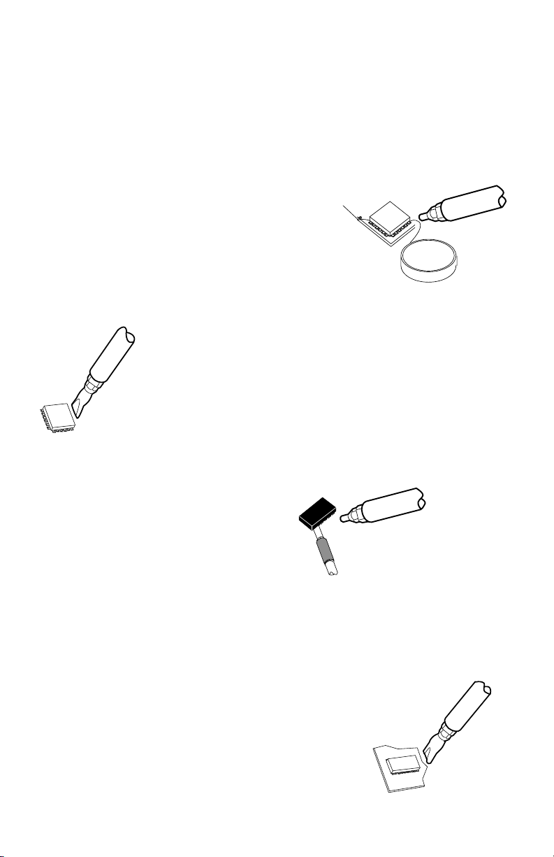
METHOD 3
Dual-Flow Tip
1. Use a Dual Flow Tip whose width comes closes to the
width of the SMD component leads.
2. Adjust temperature to about 750°F.
3. Adjust air output at around 3-5 psi.
4. Position Tool on top of the SMD (air is directed on both
sides of the connection) and move back and forth, until
solder melts.
5. Lift SMD off the board by using a pair of tweezers.
6. To resolder, use a tweezer to hold SMD in place and
align leads with the pad.
7. Direct hot air to the leads and reow the solder.
Release SMD when solder solidies.
INSTRUCTIONAL VIDEOS AVAILABLE ON 30 DAY LOAN. CALL EDSYN.
1. Have the proper Tip installed.
2. Adjust air output to about 3-4 psi.
3. Set temperature to 700°F.
4. Heat up one corner of the SMD.
5. When the solder melts, insert the
shimblade of SMD helper under the
heated area of the chip as if cutting
thru the solder connection.
6. While directing hot air ahead of the shim
at all times, cut thru the sides of the
SMD and lift it up from the board.
7. To resolder, use a Quadra-Flow Tip.


