Edsyn Soldapullt ZD500DX-230 User manual

ZD500DX-230
®
Deluxe Hot Tip
Desoldering Station
(self-contained)
Instruction manual
• COMPLIES WITH MIL-S-45743E, MIL-STD-2000-1B, WS6536E AND
ESD SPEC, DOD-STD-1686, DOD-HDBK-263
MADE
IN
U.S.A.
EMC Directive 89/336/EEC

ZD500DX-230
®
Deluxe Hot Tip
Desoldering Station
Contents at a Glance
Page 3 - 4 Features & Specications
Page 5 Operation
Page 6 - 8 Tip Usage & Replacement
Page 9 Maintenance
Page 10 Trouble Shooting & Maintenance
Page 11 Calibration
Page 11 - 13 Spare Parts List for Power Supply
Page 14 - 15 Spare Parts List for Hand Tool
Page 2

FEATURES
Static Safe
POWER SUPPLY
K
A) Tool Pod, equipped with micro-switch to activate pump.
B) Power Switch, to activate WorkStation.
C) Temp. Control Knob
D) Pump LED
E) Heater LED
F) SH232 Sponge Holder, with cleaning sponge.
G) Power output, 24V, controlled
H) AF110 Filter, (note ow direction)
I) External Calibration
J) Pump
K) WT623 Tip Wrench
L) WT619 Tip Wrench
A
B
C
E
F
D
G
J
H
I
H
L
SPECIFICATIONS
• 230V, 50/60 Hz, 150W Power Supply
• 24V, 50/60 Hz, 70W Hand Tool
• Weight; Power Supply: 5 lbs. 12 ozs. (2.6 kg)
Hand Tool: 11 ozs. (312 g)
• Temperature range of 400°F to 800°F (205°C-425°C)
• Voltage leakage from tip to ground, less than 2 MV
• Tip to ground resistance, less than 2 ohms
• COMPLIES WITH MIL-S-45743E, DOD-STD-2000-1B, WS-6536E and
ESD SPEC, DOD-STD-1686, DOD-HDBK-263 Page 3
DISTINGUISHING FEATURES
For ZD500DX-230 For ZD500DX-230P
POWER CORD WIRING
BROWN to LINE
BLUE to NEUTRAL
GRN/YEL to GROUND
For ZD500DX-230B
3A Fuse inside
For ZD500DX-230I
Not CE Approved
Power Cord

A) Head Assembly- Includes the primary
ltering system and solder debri chamber.
B) Hot Tip Desoldering Tip- Wide range of
desoldering Tips applicable.
C) Head Shaft- Allows 4-point rotation of
Head Assembly.
D) Trigger- Activates vacuum suction.
E) Vacuum Hose- Low Static silicone hose.
Connects to vacuum source.
F) Connector- To 24 V controlled output.
(for HT500) (for HT500-2)
G) Cleaning Shaft- For cleaning Desoldering
Tip orice: .05 (1.3 mm) and .025 (0.6
mm)
HT500/-1/-2 ®
Hot Tip Desoldering Tool
D
A
F (for HT500-1)
E
B
C
ESD Safe
FEATURES
HOT TIP DESOLDERING TOOL
1. Insert nut into the slot of adapter plate on both sides.
2. Screw PA233 on the adapter plate.
PA233 Dovetail Extension Bracket allows
you to install additional Tool Pods.
OPTIONS
FC641 Large Filter Cartridge Assembly
Replaces FC640. For use in applications
that require heavy use, or where No-Clean
solder/ux is used at high temperature.
Page 4

ADJUSTMENTS
The HT500 Head assembly can be adjusted into varying positions to suit the operator.
While Tool is in the Pod, push handle
down and twist handle until it locks
into 1 of it's 4 positions. Twisting
counter-clockwise will permit a 1800
turn. Twisting clockwise will permit
a 900 turn.
Note: Head Assembly does not make a full 3600 turn
To tilt the Head assembly, loosen (2)
Adjustment Screws. Tilt the Head assem-
bly to desired position. Retighten
Screws.
adjustment
screws
Air out
Vacuum
Air out
Vacuum
AIR FLOW DIRECTION Hoses must be clean and not
kinked or cracked
For Factory repair:
Specify the problem and ship the
unit to EDSYN INC.
Customer Service
15958 Arminta Street
Van Nuys, CA 91406-1896
NOTE: When Tip orice is blocked,
use a correct size Cleaning Shaft
while pressing the Trigger to clear the
obstruction.
CS468 is .05 in. dia.
CS468-1 is .025 in. dia.
OPERATION
1. Connect HT500 to 24V power supply and vacuum source.
2. Press trigger to activate vacuum.
3. Always clean the Tip with wet sponge and
always re-tin (add fresh solder) during and after each
operation.
Page 5

3. Apply AN112 (in tube) or AN122 (in syringe) Anti-Seize
Compound before assembling.
INSPECT DAILY
4. Install RS383.
WT619
Tip Wrench
1. Remove RS383. Use WT619.
2. Replace Tip and install new Tip.
1. When desoldering small
holes on at areas, tilt
Tool to allow adequate
air ow to lift solder into
chamber.
2. When using SMD Tips, heat
up the connections by posi-
tioning the Tool perpendicu-
larly. When solder melts tilt
the Tool and depress trigger.
(SMD Tips are recomended
for HT500 using external
vacuum).
DESOLDERING POINTERS
REPLACING DESOLDERING TIPS
install
remove
Multi-Layered
Board
Heavy Duty Desol-
dering Tip
3. Extra-heavy duty desoldering on a multi-layeredboard
is done by using a Heavy Duty Desoldering Tip and
a Hi-Heat Soldering Tip simultaneously. Although
pre-heating of the circuit board will speed up the
process, it is not always necessary.
Page 6

Hot Tip Desoldering Tips
When using a Replacement
Desoldering Tip to desolder
small holes on flat areas,
tilt Tool to allow adequate
air flow to lift solder into
chamber.
When using SMD Tips, heat up the
connections by positioning the Tool
perpendicularly. When solder melts,
tilt the Tool and depress trigger.
ZD12 .03 1/32 0.8
ZD13 .04 3/64 1.0
ZD14 .06 1/16 1.5 .50 1/2 12.7
ZD18 .07 5/64 1.8
ZD19 .12 1/8 3.2
ZD107 .02 1/64 0.5
ZD112 .03 1/32 0.8 .48 31/64 12.2
ZD113 .04 3/64 1.0
ZD118 .07 5/64 1.8
ZD111 .03 1/32 .08 1.22 17/32 31
ZD115 .07 5/64 1.8
ZD25 .03 1/32 0.8
ZD26 .04 3/64 1.0 .39 32/64 9.9
ZD27 .07 5/64 1.7
ZD57 .10 7/64 2.5
ZD58 .13 1/8 3.2
ZD60 .15 5/32 3.8 .55 9/16 13.9
ZD61 .25 1/4 4.5
mmin.
in.
B
HOLE DIAMETER
in. in.
PART
NO. mm
Fractional dimensions are approx.
DESCRIPTION
HOLE
DIA.
HOLE
DIA.
Standard Tip
(High Heat Transfer)
HOLE
DIA.
SMD**
(FOR ZD505/905 series)
Replacement*
Funnel
Long Funnel
To reach deep, dense and
compact areas, use a Long
Funnel tip
Extra-heavy duty desoldering
on a multi-layered board is
done by using a Medium Life
Desoldering Tip.
HOLE
DIA.
Page 7

in. in. mm in. in mm
ZD28 .03 1/32 .08
ZD29 .04 3/64 1.0
ZD30 .06 1/16 1.5
in. in. mm .30 5/16 7.6
ZD70
.08 3/32 2.0
ZD71
B
PART
NO.
HOLE DIAMETER
DESCRIPTION
HOLE
DIA.
Economy**
Surface
Sweep** W
Hot Tip Desoldering Tip
Replacement
Desoldering Tip
SMD Desoldering Tip
Medium & Long Life
Desoldering Tip
Hole Dia. = .06 in.
Side Sweep**
Hole Dia. = .06 in.
*Tin New Iron Tips at Low Temperaturebefore using.
**Non-Plated Alloy
Hot Tip set-up
Heater Set-up
Side Sweep Tips
allows removal of
solder from the com-
ponent side of the
board.
Surface Sweep Tips
removes excess solder
on pads for atter surface,
prior to SMD remount-
ing.
RS383
Retaining
Sleeve
AC736
Tip Adapter
HT01
AC737
Accumulator Bushing
Side Sweep
Desoldering Tip HC273
Threaded
Retaining
Collar
Page 8

TO REPLACE O- RINGS INSIDE VALVE ASSEM-
BLY
a) Unscrew Lock Nut at the end of the HT500
Handle.
b) Remove Handle Cover.
c) Slide out Valve Assembly while placing your nger
over the Spring Seat. BE CAREFUL NOT TO LET
THE SPRING AND THE SPRING SEAT SHOOT
OUT FROM THE HOUSING
d) Clean all parts with alcohol only.
e) Replace OS730 O-Ring Set (set of 3).
f) Lube new O-rings with OL111 O-Ring Lube.
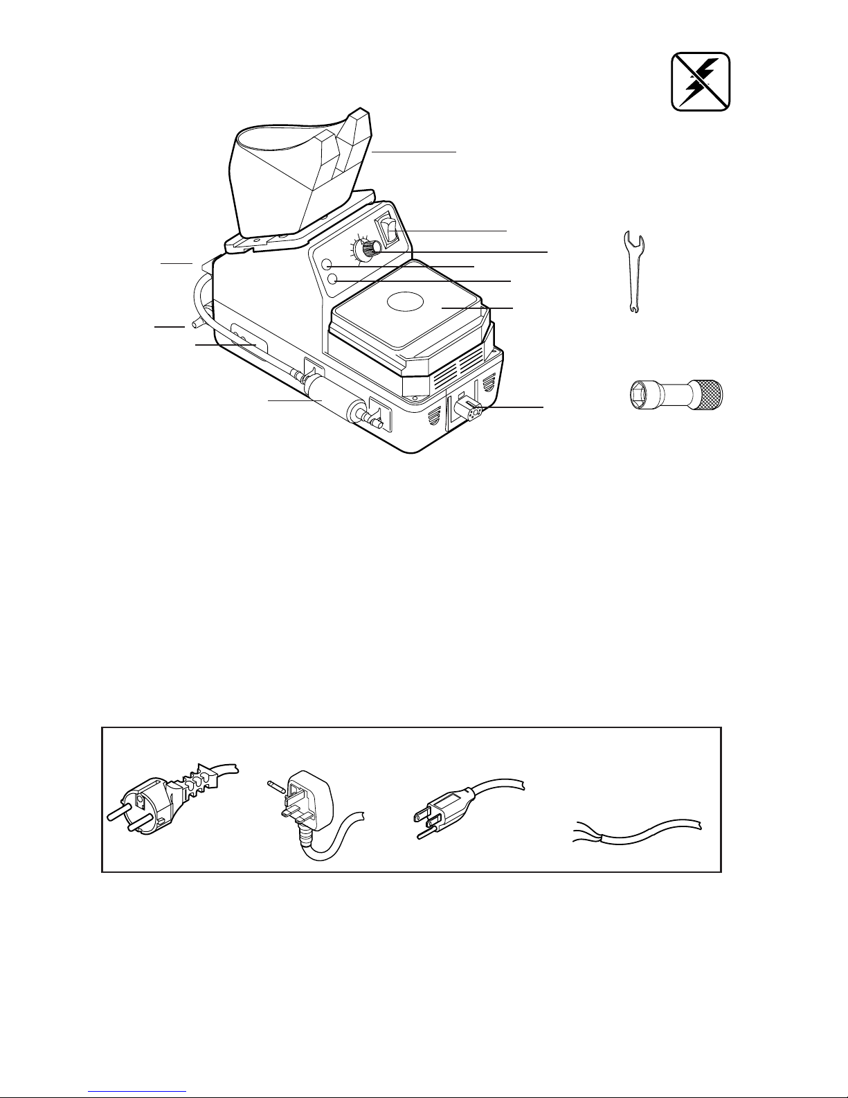
Valve Assembly
Handle
Cover
Lock Nut
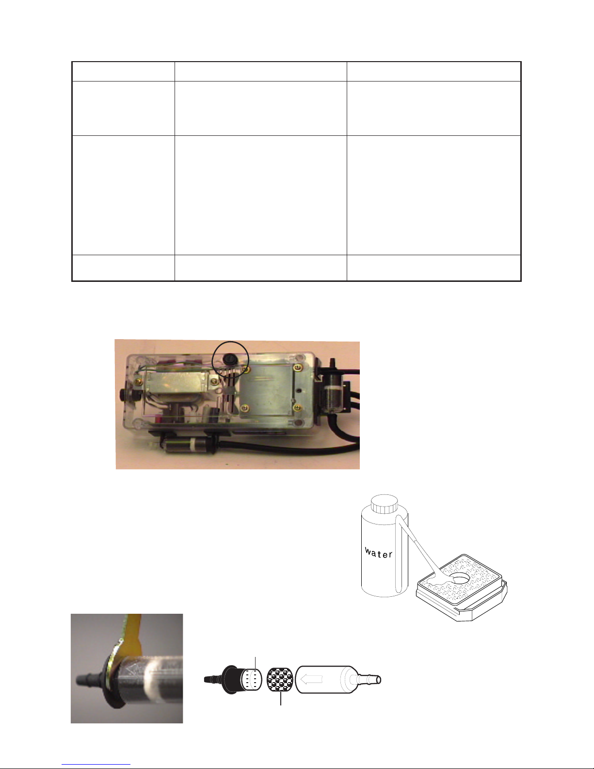
DAILY MAINTENANCE WEEKLY MAINTENANCE
SC525 MS229 OS133
©®®©
AF625
©
OS731
FC639
©OS132
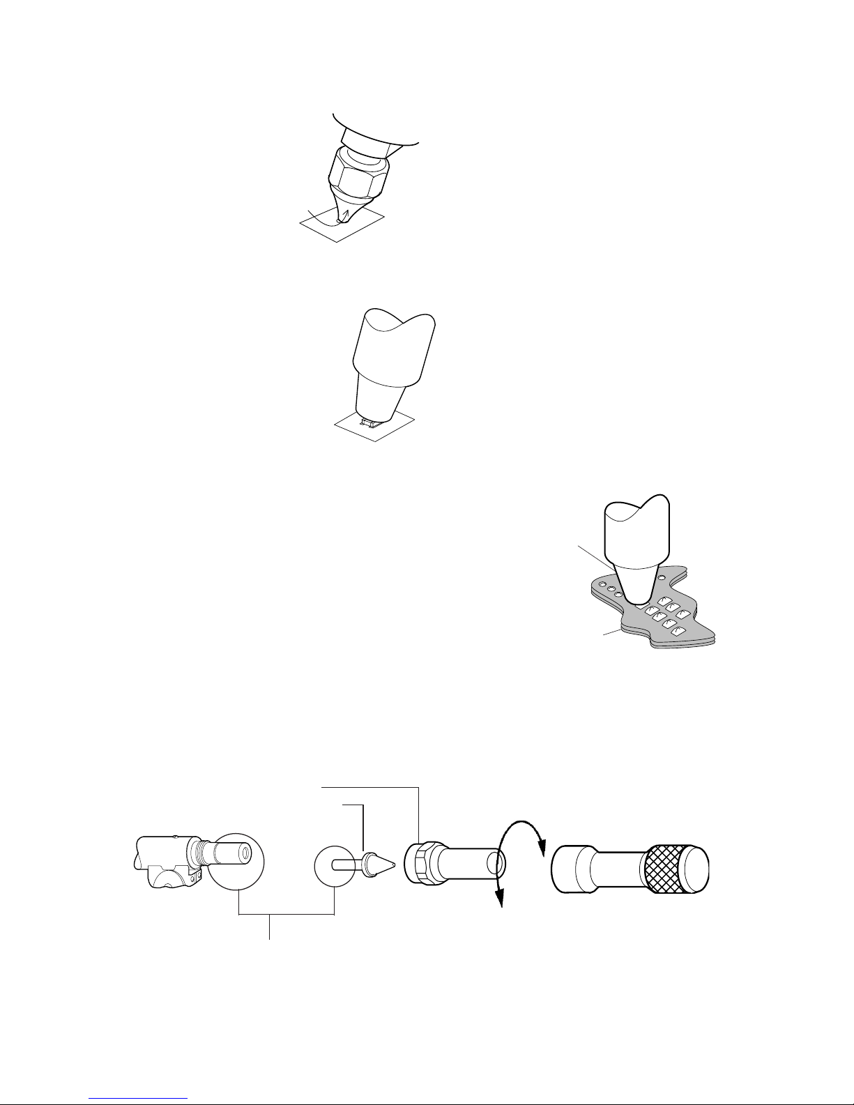
When installing OS133, the HT01
should go thru the OS133.
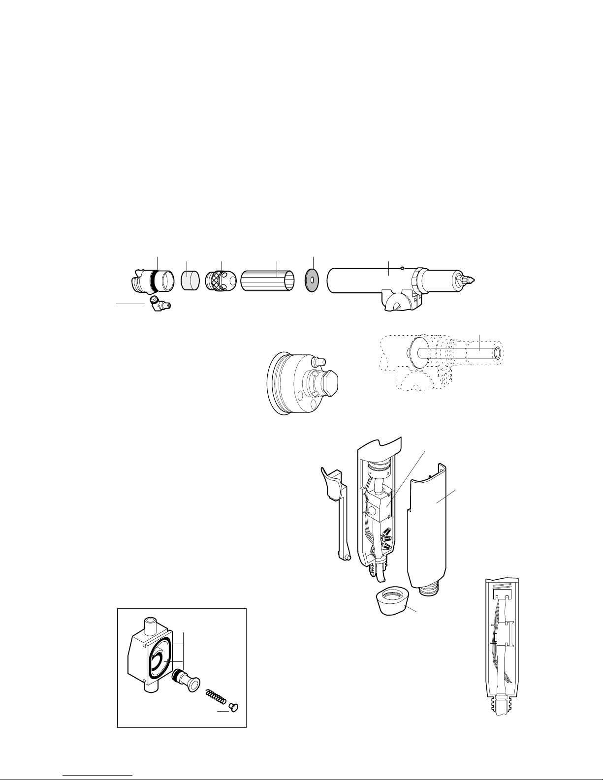
®Desoldering
Head Housing
• Remove and inspect Tip and Heater Assy.
• Inspect all Filters
• Remove solder debri from Desoldering Head
Housing
• Inspect Valve Assy.
• Inspect all O-Rings and Seals
TO REPLACE FILTER & O-RING INSIDE
DESOLDERING HEAD ASSY.
1. Pull out FC639 from Housing.
2. Unscrew SC525 from FC639 to remove AF625.
3. Insert new AF625 inside SC525 and screw back
on.
4. Clean and apply OL111 on OS731 & OS132
O-Ring.
CAUTION: Make
sure the wires are
not pinched by
Valve Assembly.
Spring Seat
OS730 O-ring set
HT01
OS133
© - Clean
® - Replace
OPTIONAL FC641
Large Filter Cartridge Assembly
1. Pull out FC641 from Housing.
2. Unscrew FC641 remove old AF041.
3. Insert new AF641 inside FC641 and
screw back together.
4. Clean and apply OL111 on OS731 &
OS132 O-Ring.
Page 9

SPONGE MAINTENANCE
Replace RS199 Cleaning Sponge
Pour water on RS199 to moisten it completely.
DO NOT OVERFILL.
End Cap
AF629 Felt Filter
AF040 Foam Filter
Housing
Tip Wrench can be use
to remove lter cap.
FILTER MAINTENANCE
Filters should be kept clean
Problems that occur aside from those listed below
should be handled by our factory technicians.
TROUBLE SHOOTING
Pump running but
weak or no vacuum
generated.
Pump won't run
Symptoms Cause Remedy
Blown fuseNo power Replace fuse. See spare parts list
a) Loose connections between
joints or connectors.
b) Dirty lters.
c) Leaky or sticky valve.
d) Wrong hose connection.
e) Broken pump diaphram.
a) Pump micro switch is stuck.
b) Vacuum inside hose (normal)
a) Make sure all connections are
tight.
b) Inspect and clean all lters.
Replace elements if needed.
c) Clean parts and replace
O-Rings if needed .
d) HT500 Hose should be
connected to AF110.
e) Ship back to factory
a) Use a pair of tweezers to release
the switch.
b) Squeeze trigger to release
vacuum.
3.15A fuse inside
FUSE REPLACEMENT
Page 10

ZD500DX-230 Spare Parts List
See next page for illustration
AIR MOVEMENT WILL AFFECT THE TEMPERATURE READING.
WORK IN AN AREA WHERE THIS IS MINIMAL.
CALIBRATION
1. Using a clean Tip, turn on power and
set Temperature Control Knob to
approx. 500°F (260°C). Allow Tip
to warm up.
2. Tin the tip properly and place center
of the thermo-couple wire on tip.
3. Apply a small amount of solder on
the center of the thermo-couple wire,
to form a good contact between the
tip and the thermo-couple wire.
4. Set Temperature Control Knob to
400°F (205°C).
5. Adjust LO-Temp. Calibration Pot so
the Meter will read 400°F (205°C).
6. Set Temperature Control Knob to
800°F (427°C).
7. Adjust HI-Temp. Calibration Pot so
the Meter will read 800°F (427°C).
1. Set knob at 400°F.
2. Adjust LO to 400°F.
3. Set knob at 800°F.
4. Adjust HI to 800°F.
HI LO
Temperature
Control Knob Calibration Pot
Page 11
44 SR011 Screw, Round Head Phillips, 6-18 x 5/8 4
45 SR251 Bump-Ons 4
46A SR318 Power Cord Only, (european plug) 1
46B SR454 Power Cord Only, (british plug) 1
46C SR026 Power Cord Only, (NEMA plug) 1
46D SR163 Power Cord Only, (no plug) 1
47 WT623 Tip Wrench, Dual Open End, 1/4" & 3/4" 1
48 SR416 Holder, Tip Wrench Hanger 1
QTY
REQ'D
ITEM
NO. PART NO.DESCRIPTION

3
2
17
14
15
18
13
10
11
8
9
5
16
4
19
20
21
23
24
25
26
27
28
31
36
33D
34
33
32
37
41
40
31
35
31
39 44
45
42
43
34
12
47
48
7
1
6
6
33B 33C
33A
46C
29
5
49
Page 12
46D
46A
46B

ITEM
NO. PART NO.DESCRIPTION QTY
REQ'D
1 SR566 Top Cover, Power Supply 1
2 SR452 Power Switch, 230V 1
3 SR073 Tool Holder 1
4 SR035 Adapter plate 1
5 SR467 Nut, Square Cone 3
6 SR367 Screw, Flat Head Phillips, 6-32 x 5/8 2
7 SH232 Sponge Holder 1
8 SR137 Washer, #8 1
9 SR009 Screw, Pan Head Slotted, 8-32 x 7/8 1
10 SR865 LED Assy. Yellow, for pump 1
11 SR573 LED Assy. Green 1
12 RS199 Cleaning Sponge 1
13 SR567 Label, Front Panel 1
14 SR115 Retainer Plate for Micro Switch 1
15 SR114 Push Rod for Micro Switch 1
16 SR045 Knob, Temperature Control 1
17 SR112 Flange, Retainer for Tool Pod 1
18 SR568 Micro Switch Assy. 1
19 SR243 Potentiometer Assy. 1
20 SR255 Spacer, for Potentiometer Assy. 1
21 SR050 Cable Tie 1
23 HL603 Hose, Low Static Silicone, 3/16 ID. (sold per foot) 2@
7" and 10"
24 SR484 Bottom Base 1
25 SR491 Pump / Motor Assy. 230V 1
26 SR539 Transformer, Dual Primary, 24V output 1
27 15242W70 Circuit Board 1
28 SR569 Fuse Holder, Panel Mount 1
29 SR711 Connector Assy. 1
31 SR016 Washer, #6 6
32 SR017 Nut, 6-32 3
33 AF110 Filter, In-Line Vacuum 2
33A SR266 End Cap 2
33B AF629 Felt Filter (set of 10) 2
33C AF040 Foam Filter (set of 10) 2
33D SR533 Barrel, Clear, for AF110 2
34 SR439 Holder, Clip 4
35 SR561 Screw, Round Head Phillips, 6-32 x 3/4 1
36 SR468 Screw, Round head Phillips, 6-32 x 7/8 4
37 SR139 Washer, Star 4
39 SR144 Screw, Round Head Slotted, 6-32 x 1/2 1
40 SR469 Spacer, for Pump Mounting 4
41 SR470 Well Nuts, for Pump Mounting 4
42 SR563 Fuse, 1.6A 1
43 SR310 Label, Calibration, Left Rear 1
Page 13

32
3
19
26
24
11
28
37
41
27
20
12
13
16
17
18
14
50
29
2
1
30
10
42
22
21
25
47
25
46
49
47 9
45
6
5
7
8
33
30
43
36
38
15
4
31
39
40
35
34
44
48
HT500/-1 HOT TIP
DESOLDERING TOOL
SPARE PARTS LIST
1 RS383 Retaining Sleeve 1
2 ZD13 Hot Tip Desoldering Tip 1
3 HT01 Hot Tube 1
4 AC737 Accumulator Bushing 1
5 MS229 Mica Sheet 1
6 OS133 Silicone Washer 1
7 SC525 Solder Cone 1
ITEM
NO.QTY
REQ'D
DESCRIPTION
PART NO.
Page 14

8 AF625 Felt Filter 1
9 SR148 Housing for End Cap 1
10 OS731 O-Ring for End Cap 1
11 OS132 O-Ring for End Cap Elbow Connector 1
12 SR147 Connector for End Cap 1
13 FC639 End Cap 1
14 SR008 Flat Head Slotted Screw for Index Flange 1
15 SR168 Pan Head Phillip Screw for adjusting Desoldering Head Assy. 1
16 HT500H Desoldering Head Assembly- Repairable by EDSYN Customer Service Dept. 1
17 SR136 Desoldering Head Housing 1
18 SR120 Heater Element 1
19 SR117 Heater Element Bushing (O-Ring included) 1
20 SR118 Retaining Key for Heater Element Bushing 1
21 SR119 Teon Spacer for Heater Element 1
22 OS731 O-Ring for Heater Bushing 1
24 SR121 Grounding Wire 1
25 SR122 Screw, 2-56 x 1/8 Pan Head Slotted 3
26 SR145 Sleeving, Braided Fiberglass 2
27 SR004 Handle Cover 1
28 SR124 Head Shaft 1
29 SR125 Spring for Head Shaft 1
30 SR126 Washer, Nylon 2
31 SR127 Retaining Nut for Head Shaft 1
32 SR128 Trigger 1
33 HL603 Hose, Low Static Silicone, 3/16" I.D. 5"
34 SR335 Valve Assy. 1
35 SR393 Nut, Retaining, for Handle 1
36 OS730 O-Ring Set (Three O-Rings) 1 set
37 SR129 Valve Housing 1
38 SR130 Poppet (O-Ring Included) 1
39 SR131 Return Spring for Poppet 1
40 SR132 Seat for Return Spring 1
41 SR133 Wire Nuts 3
42 SR134 Hose and Wiring Assembly for HT500 1
SR565 for HT500-1 SR635 for HT500-2
43 SR123 Handle Base 1
44 SR143 Wire Guide, Nylon, 3/8" Length 2
45 SR005 Index Flange (Screw Side) 1
46 SR006 Index Flange (Nut Side) 1
47 SR007 Nut, Hex, 2-56 thread 3
48 SR135 Connector for HT500 1
SR353 for HT500-1 SR633 for HT500-2
49 SR170 Cap Nut, Hex #8-32 x 5/16" 1
50 SR169 Washer, Flat, 1/16" thick 1
PART NO. QTY
REQ'D
DESCRIPTION
ITEM
NO.
Page 15

ZD500DX-230 Instruction Manual
THE NAMES LONER, SOLDAPULLT, SOLDAVAC, ATMOSCOPE
AUTO-VAC, IDLE-REST, OCTAVAC AND KLATCH
ARE REGISTERED TRADEMARKS OF EDSYN, INC.
MOST PRODUCTS ARE COVERED BY U.S. AND
FOREIGN PATENTS AND PENDING APPLICATIONS.
DESIGN, COLOR AND MATERIALS
SUBJECT TO CHANGE WITHOUT NOTICE.
TIP STYLE ON SOLDERING, DESOLDERING AND HOT AIR TOOLS MAY VARY.
PRINTED IN U.S.A.
ALL RIGHTS RESERVED.
NO PART OF THIS PUBLICATION INCLUDING THE INDIVIDUAL ICONS
MAY BE REPRODUCED OR UTILIZED IN ANY FORM OR BY ANY MEANS
WITHOUT THE PERMISSION OF EDSYN, INC.
ZD500DX-230i.pdf
FORM.913 Rev D
Intellectual
Property
©Copyright EDSYN, Inc. 2002
Other manuals for Soldapullt ZD500DX-230
1
This manual suits for next models
1
Table of contents
Other Edsyn Power Tools manuals
Popular Power Tools manuals by other brands

Jet
Jet EQUIPMENT &TOOLS SBR-30N Operating instructions and parts manual

EINHELL
EINHELL E-PST operating instructions

Westfalia
Westfalia HPLCD 2000 Original instruction manual

Batavia
Batavia MAXXPACK BT-CMT003 operating instructions

Milwaukee
Milwaukee v 1828c Instructions for use

Nibco
Nibco PC-20M instruction manual