Efka AB600A5015 User manual

- AB600A5015
FRANKL & KIRCHNER EFKA OF AMERICA INC. EFKA SINGAPORE PTE. LTD
GMBH & CO KG .
CONTROL AB600A5015
Operating manual
With parameter list
-Putting into Service
-Settings
-Functional Description
-Connection Diagrams
-Timing Diagrams
No. 402447 English

Important Notes
The particulars used in various figures and tables, such as type, program number, speed, etc.,
serve as examples. They may differ from those in your display.
For current versions of the Instructions for Use and Lists of Parameters, necessary for operating EFKA drives
in accordance with regulations, please refer to the EFKA web site www.efka.net, page “Downloads”.
On our web site, you will also find the following supplementary instructions for this control:
General instructions for use and programming
Use with USB Memory Stick
Adapter cords

- AB AB600A5015 Instruction Manual
- 3 -
CONTENTS Page
1Range of Applications 6
1.1 Use in Accordance with Regulations 6
2Scope of Supply 6
2.1 Special Accessories 7
3Putting into Service 7
4Setting and Putting into Service with the Aid of the Fast Installation Routine (SIR) 7
5Quick access 10
5.1 Parameter back up 10
5.1.1 Parameter backup 10
5.1.2 Restoring parameters from the backup 10
5.1.3 Save the parameter backup on a USB stick 11
5.1.4 Restoring the parameter backup from the USB stick 12
5.2 Setting the reference position 13
6Setting the Basic Functions 14
6.1 Direction of motor rotation 14
6.2 Use of a HSM001 Hall Sensor Module or IPG... Pulse Encoder 14
6.3 Transmission Ratio 15
6.4 Selection of Functional Sequences (Thread Trimming Operations) 15
6.5 Key functions of the input in1 15
6.6 Positioning speed 15
6.7 Maximum Speed Compatible with the Sewing Machine 16
6.8 Maximum speed 16
6.9 Positions 16
6.9.1 Setting the reference position (Parameter 170) 17
6.9.2 Setting the positions 17
6.10 Control display of signal position and stop position 18
6.11 Positioning shift 18
6.12 Braking Characteristics 18
6.13 Braking Power at Standstill 18
6.14 Starting Characteristics 19
6.15 Operating hours counter 19
6.15.1 Set and Reset Operating Hours Counter 20
6.15.2 Total Operating Hours Display 20
7Functions 20
7.1 Softstart 20
7.1.1 Softstart speed 20
7.1.2 Softstart stitches 20
7.2 Sewing foot lifting 21
7.3 Reverse motor rotation 21
7.4 Unlocking the Chain (Mode 5/6/7) 22
7.5 Machine run blockage 23
7.6 Thread trimming operation 23
7.6.1 Thread Trimmer/Thread Wiper (Lockstitch Modes) 23
7.6.2 Trimming speed 23
7.6.3 Chainstitch thread cutter (var. modes) 24

- AB600A5015 Instruction Manual
- 4 -
7.6.4 Chainstitch Machine Trimming Signal Times 24
7.7 Overlock Machine Functions (Mode 7) 24
7.7.1 Start and End Counts 24
7.8 Tape Cutter/Fast Scissors (Modes 6/7) 25
7.8.1 Tape Cutter/Fast Scissors in Mode 7 25
7.9 Manual Tape Cutter/Fast Scissors 25
7.10 Seam with Stitch Counting 25
7.10.1 Number of Stitches for a Seam with Stitch Counting 25
7.10.2 Stitch Counting Speed 26
7.10.3 Seam with Stitch Counting When Light Barrier Is On 26
7.11 Free Seam and Seam with Light Barrier 26
7.12 Light barrier 27
7.12.1 Speed after Light Barrier Sensing 27
7.12.2 General Light Barrier Functions 27
7.12.3 Reflection Light Barrier LSM002 27
7.12.4 Automatic Start Controlled by Light Barrier 28
7.12.5 Light barrier filter for knitted fabrics 28
7.12.6 Functional Variations of the Light Barrier Input 28
7.13 Switching Functions of Inputs in1...i13 29
7.14 Software Debouncing of All Inputs 29
7.15 Special pedal function Single stitch / Full stitch 30
7.16 Signal “Machine Running“ 30
7.17 Signal Output Position 2 30
7.18 Signal Output 512 Impulses per Rotation (G1 or G2) 30
7.19 Actuator 31
7.19.1 Analog actuator 31
8Signal Test 31
8.1 Inputs to the control 31
8.1.1 Outputs of control 32
9Table of Machine Functions and Adapter Cords 33
10 Operating Elements and Socket Connectors 34
10.1 Positions of the Front Side 34
10.2 Positions of the rear side 34
10.3 Connection Diagrams 35
11 Timing Diagrams 38
12 Parameterlist 50
12.1 Operator Level 50
12.2 Technical level (Code no. 1907) 52
12.3 Supplier level (Code No. 3112) 55
13 Error Displays 59

- AB AB600A5015 Instruction Manual
- 5 -

- AB600A5015 Instruction Manual
- 6 -
1 Range of Applications
The drive is suitable for lockstitch, chainstitch and overlock machines of various manufacturers.
The functions backtacking and stitch compression, are unsupported.
1.1 Use in Accordance with Regulations
The drive is not an independent functional machine. It has been designed for integration into other machines by
trained specialists.
It must not be put into service until the machinery into which it is to be incorporated has been declared in
conformity with the provisions of the EC Directive (Appendix II, paragraph B of the Directive 89/392/EEC and
supplement 91/368/EEC).
The drive has been developed and manufactured in accordance with the relevant EC standards:
IEC/EN 60204-31 Electrical equipment of industrial machines:
Particular requirements for industrial sewing machines, sewing units and sewing systems.
Operate the drive only in dry areas.
ATTENTION
When selecting the installation site and the layout of the connecting cable, the Safety
Instructions must be followed with no exceptions.
Particular attention should be paid to maintaining the proper distance from moving parts!
2 Scope of Supply
Standard Scope of Supply
1
Direct current motor
DC1200 optional DC1250
1
Electronic control
AB600A5015
1
Actuator
EB401
1
Set of accessories (standard)
B156
consisting of:
Plastic bag for B156 + documentation
and
1
Set of accessories
Z74
consisting of:
Plastic bag with connector housing 8 pol.
Molex Minifit and contacts, potential
equalization cord
Option 1
1
Actuator
EB401
and
1
Set of accessories
Z73
consisting of:
Plastic bag with connector housing 8 pol.
Molex Minifit and contacts,pitman rod with
2. ball socket, potential equalization cord
Zusätzliche Optionen
Undertable mounting kit
Z71 AB6..-DC12.. Undertable mounting
Pulse encoder IPG001
Z72 AB6..-DC12.. IPG
NOTE
If there is no metallical contact between drive (motor) and machine head, the potential equalization cord
supplied with the unit is to be wired from the machine head to the terminal provided on the control box!

- AB AB600A5015 Instruction Manual
- 7 -
2.1 Special Accessories
The special accessories available ex works allow the augmentation and enhancement of functions, operating,
connecting, and mounting options.Since the range of available components is continually expanded, we kindly
ask you to contact us in case of need.
Designation
Material No.
Reflection light barrier module LSM002
6100031
Hall sensor module HSM001
6100032
Pulse encoder IPG001
6100033
Extension cable approx. 1000 mm long for commutation transmitter DC12.. + DC15..
1113151
Extension cable approx. 1000 mm long for Netz DC12.. line + DC15..
1113150
Potential equalization cord 700 mm long, LIY 2.5 mm2, gray, with spades on both
sides
1100313
Foot control type FB302B with three pedals for standing operation, with
approx. 1400 mm connecting cable and plug
4170025
Fitting piece for position transmitter
0300019
Adapter set for DC12. + DC15.. on PEGASUS model W600
1113125
Adapter set for DC12. + DC15.. on PEGASUS Ex/Ext
1113126
Adapter set for DC12. + DC15.. on PEGASUS model W1500N, W1600
1113647
Undertable mounting kit for DC1200/DC1250
1113956
Undertable mounting kit for DC1500/DC1550
1113235
Undertable mounting kit for DC1500/DC1550
1113427
9-contact SubminD male connector
0504135
9-contact SubminD female connector
0504136
Half-shell housing for 9-contact SubminD
0101471
Adapter set direct drives DC1210 & DC1230
Mounting kit for DC1210 on JUKI M067, M069
1114085
Mounting kit for DC1210 on JUKI M068
1114093
Mounting kit for DC1210 on PEGASUS EX
1114082
Mounting kit for DC1210 on PEGASUS M900
1114088
Mounting kit for DC1210 on YAMATO AZ, CZ
1114084
Mounting kit for DC1230 on PEGASUS chainstitch
1114119
Mounting kit for DC1230 on YAMATO VC, VE, VF, VG
1114102
3 Putting into Service
Before putting the control into service, the following must be ensured, checked and/or adjusted:
Selection of motor type using parameter 467
The correct installation of the drive, position transmitter and accompanying devices, if necessary
The correct selection of the trimming operation using parameter 290
If necessary, the correct adjustment of the direction of motor rotation using parameter 161
The correct selection of the functions of keys (inputs) using parameters 240...246
The setting of the transmission ratio between motor shaft and machine shaft using parameter 272
The setting of the type of position sensor using parameter 270
If necessary, the adjustment of the positions using parameter 171
if necessary, the setting of the positions using parameter 171 (possible with all settings of parameter 270)
The correct positioning speed using parameter 110
The correct maximum speed compatible with the sewing machine using parameter 111
The setting of the remaining relevant parameters
Begin sewing in order to save the set values
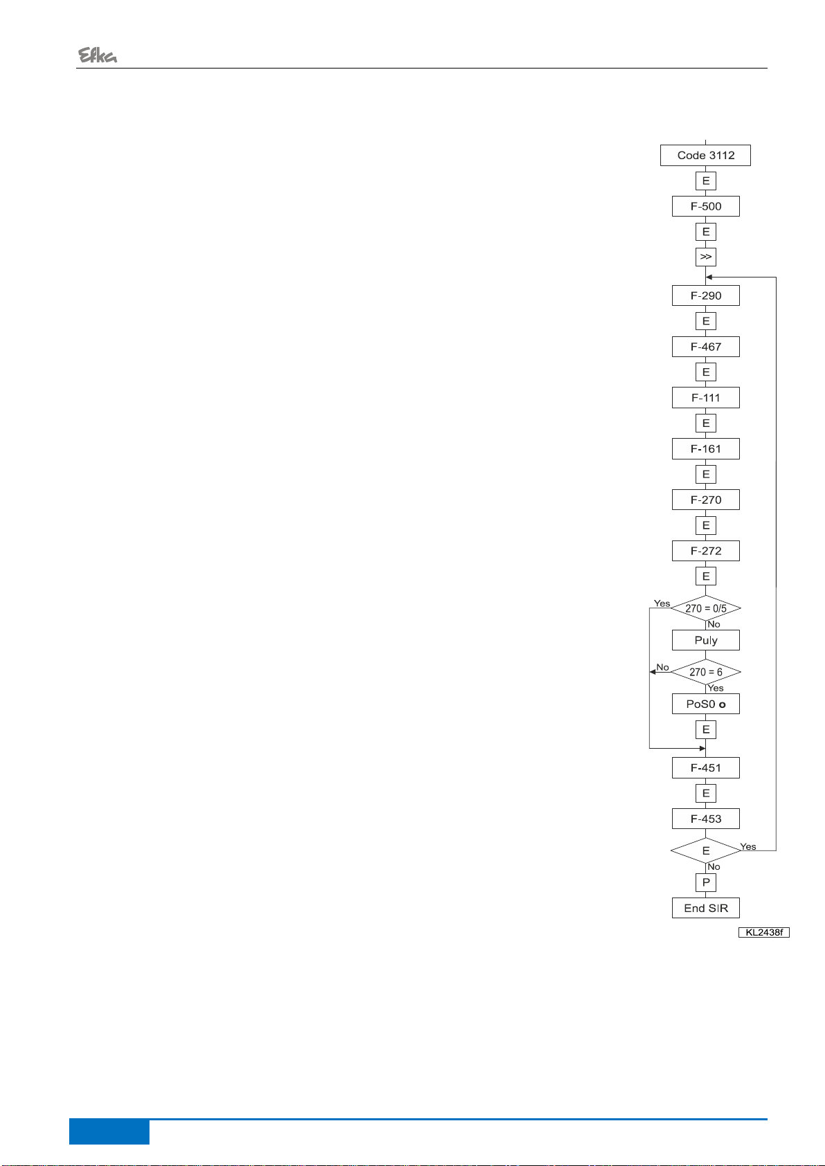
4 Setting and Putting into Service with the Aid of the Fast Installation
Routine (SIR)
Function
Parameters
Call-up of the Fast Installation Routine SIR
(Sir)
500
The Fast Installation Routine (SIR) passes through all parameters necessary for programming the functional
sequence and the positions.

- AB600A5015 Instruction Manual
- 8 -
With SIR you can do the most important settings for initial operation with menu prompting.
For safety reasons, the menu must be executed point by point. This ensures correct setting of all important
parameters.
Input of the code number for the fitting level.
Parameter 500 is displayed.
Parameter 290 for functional sequence of the cutting procedures.
Parameter 467 for selection of motor.
Parameter 111 for the maximum speed.
Parameter 161 for direction of motor rotation.
Parameter 270 for type of position sensor.
Parameter 272 for transmission ratio.
Important! The transmission ratio should be determined and
indicated as precisely as possible.
If parameter 270 =0 or 5, continue with input of 451.
Check the transmission ratio.
Move pedal forwards. Let the drive run until ready (rdy) is displayed.
Press pedal to position 0. The check is complete.
if parameter 270 = 6, set the reference position.
Turn hand wheel until symbol odisplay goes off.
Set reference position (e.g. height of the stitch plate, lower dead point).
Parameter 451 for position 1.
Parameter 453 for position 2.
To repeat the cycle from parameter 290, push button E.
Or end with button P(2x).
The values can be varied by pressing key +/-.
The input of the code number is described in the general operating manual!

- AB AB600A5015 Instruction Manual
- 9 -
Setting on the operating part of the controls (onboard)
1
Input code number 3112!
2
Press the Ekey
Parameter 5.0.0. displayed
3
Press the Ekey
Sir displayed. The 2 lower segments of the right 7 segment display flash.
4
Press the >> key
Parameter 2.9.0. appears
(Functional cycle cutting
processes)
5
Press the Ekey
Parameter value e.g. 05 appears.
6
Press the +/-key
The parameter value can be changed.
7
Press the Ekey
Parameter 4.6.7. appears
(Selection of motor)
8
Press the Ekey
Parameter value e.g. 3appears.
9
Press the +/-key
The parameter value can be changed.
10
Press the Ekey
Parameter 1.1.1. appears
(Maximum speed)
11
Press the Ekey
Value of the set speed appears.
12
Press the +/-key
The parameter value can be changed.
13
Press the Ekey
Parameter 1.6.1. appears
(Direction of motor rotation)
14
Press the Ekey
Parameter value e.g. 1appears.
15
Press the +/-key
The parameter value can be changed.
16
Press the Ekey
Parameter 2.7.0. appears
(Type of position sensor)
17
Press the Ekey
Parameter value e.g. 0appears.
18
Press the +/-key
The parameter value can be changed.
19
Press the Ekey
Parameter 2.7.2. appears
(Transmission Ratio)
20
Press the Ekey
Parameter value e.g. 1000 appears.
21
Press the +/-key
The parameter value can be changed.
22
If parameter 270 =0 or 5, or the check of the
transmission ratio is already done, continue with
Point 30.
23
Press the Ekey
PULY is displayed.
(Check the transmission ratio)
24
Move pedal forwards
Let the drive run until ready (rdy) is displayed.
For a maximum speed that is too high, an error
message A12 is generated. Push button Eas
often as needed until parameter 111 (Point 12) is
reached again to set the permitted maximum
speed.
25
Press pedal to position 0
(neutral)
The check is complete.
26
When parameter 270 ≠ 6, continue with Point
31.
27
P0 o is displayed (oin red).
(Setting the reference position)
28
Rotate the hand wheel in the running direction until oextinguishes *.
Set reference position (e.g. height of the stitch plate, lower dead point).
29
Press the Ekey
Parameter 4.5.1. appears
(Position 1 leading edge,
position 1 trailing edge is
automatically set 60° higher)
30
Press the Ekey
Angle from position 1 is displayed.
31
Turn the hand wheel
Set position 1 (at least 1 rotation *).
32
Or press the +/-key
The parameter value can be changed.
33
Press the Ekey
Parameter 4.5.3. appears
(Position 2 leading edge,
position 2 trailing edge is
automatically set 60° higher)
34
Press the Ekey
Angle from position 2 is displayed.
35
Turn the hand wheel
Set position 2 (at least 1 rotation *).
36
Or press the +/-key
The parameter value can be changed.
37
Upon pressing the Ekey once more the program returns to parameter 2.9.0.!
38
Press the Pkey twice
The system exits the SIR routine.
*) All operations carried out by turning the hand wheel must always be carried out in the direction of rotation set up on the
machine. Under no circumstances should you turn against the machine direction.

- AB600A5015 Instruction Manual
- 10 -
5 Quick access
These are button combinations that are linked in the direct access with settings & function of the control. Quick
access can, however, can only be used with machines that are already set up.
5.1 Parameter back up
When the machine has been completely set up, the settings should be backed up.
5.1.1 Parameter backup
Turning off the
controls
Hold the E button down & turn on
the controls
(Hold down the E button 5 sec after
turning on)
"SAVE" is shown
on the display
Press the E button
once, to execute the
backup process
When the process is completed,
"rdy" is displayed for 1 second
Turning off the
controls
5.1.2 Restoring parameters from the backup
Turning off the
controls
>>-Hold the button down (5 sec) &
turn on controls
"LOAD" is shown on
the display
Press the E button
once, to execute the
backup process
When the process is completed,
"rdy" is displayed for 1 second
Turning off the
controls

- AB AB600A5015 Instruction Manual
- 11 -
5.1.3 Save the parameter backup on a USB stick
(The parameters can be views with a text editor or Microsoft Word. The parameters in this file must not be
changed!)
Insert an empty USB
Stick
Wait until "USB" shows on the
display and press the P key
Use the +/- buttons to get to
parameter F-532. (".5.3.2" is
shown on the display)
Use the +/- buttons to
get to parameter F-
532. (".5.3.2" is shown
on the display)
Press the E button
once
Press the >> button
Press the E button
When the process is
completed, "rdy" is
displayed for 1 second
Turn off

- AB600A5015 Instruction Manual
- 12 -
5.1.4 Restoring the parameter backup from the USB stick
This process does not change the actual parameter settings. To load the backup to the current parameter
setting, execute Chapter 5.1.2 "Restoring parameters from backup".(After this process)
Insert the USB stick with
the file "0100DATA.PAB"
Wait until "USB" shows on
the display and press the P
key
Use the +/- buttons to get to
parameter F-533. (".5.3.3"
is shown on the display)
Use the +/- buttons
to get to parameter
F-533. (".5.3.3" is
shown on the
display)
Press the E button once
Press the >> button
Press the E button
Press the E button once,
to execute the backup
process
When the process is
completed, "rdy" is
displayed for 1 second
Turn off

- AB AB600A5015 Instruction Manual
- 13 -
5.2 Setting the reference position
(For detailed instructions refer to Chapter Fehler! Verweisquelle konnte nicht gefunden werden. Setting the
Reference Position (Parameter 170)
Hold down the button and
switch on the controls
(Until Pos0 show for 1
second)
Press the E button
"P0" and a rotating
"u" are displayed
Turn the handwheel until
the rotating "u" disappears
Bring the handwheel to
the zero position (needle
up / OT)
Press the E button
Turn off
Note: If the rotating "u" does not disappear after 10 rotations, change the direction of rotations.

- AB600A5015 Instruction Manual
- 14 -
6 Setting the Basic Functions
6.1 Direction of motor rotation
Function
Parameters
Direction of motor rotation
(drE)
161
161 =0
Clockwise motor rotation (look at the motor shaft)
161 =1
Counterclockwise motor rotation
ATTENTION
If the motor is mounted differently, e. g. at a different angle or with gear, make sure that the
value set using parameter 161 corresponds to the direction of rotation.
6.2 Use of a HSM001 Hall Sensor Module or IPG... Pulse Encoder
Representation and installation of a HSM001 Hall sensor module or IPG... pulse encoder !
Operation with HSM001 Hall sensor module
Operation with IPG... pulse encoder
- Get machine to the needle-up position.
- Position bore for magnet such that the magnet is located
approx. 15° after the sensor in the sense of rotation.
- Get machine to the needle-up position.
- Turn disk in the pulse encoder such that the leading edge
will be located approx. 15° after the sensor on the board
in the sense of rotation.

- AB AB600A5015 Instruction Manual
- 15 -
6.3 Transmission Ratio
NOTE
The transmission ratio must always be input if no transmission ratio of 1:1 exists, because only motors with
integrated incremental transmitters will be used. The transmission ratio should be determined and set as
precisely as possible!
The transmission ratio between motor shaft and shaft of the sewing machine head must be input, so that the set
speeds of parameters 110...117 correspond to the sewing speeds.
Function
Parameters
Transmission ratio between motor shaft and machine shaft
(trr)
272
The transmission ratio can be selected within a range of 150...40000 using parameter 272.
Example: With a motor pulley diameter of 40 mm and a sewing machine head pulley diameter of
80 mm the value 500 can be calculated using the formula below.
If the value 2000 has been selected in parameter 272, it follows that the motor pulley is
double the size of the sewing machine head pulley.
Motor pulley diameter
Value of parameter 272 =
-------------------------------------------------------------------- x 1000
Machine pulley diameter
6.4 Selection of Functional Sequences (Thread Trimming Operations)
This drive is suitable for different lockstitch, chainstitch and overlock machines. The mode for the functional
sequence required on the respective machine can be selected using parameter 290.
ATTENTION
Before switching the functional sequences, you must disconnect input and output plug-and-
socket connections between control and machine. Please ensure that the functional sequence
(mode) suitable for the respective machine is selected.
Settings with parameter 290 are possible only after the power is turned On.
You will find a summary of the modes that can be set and the corresponding machines and adapter cords, to
include available output signals in the List of Parameters chapter: Table of adapter cords.
Further information see chapter "Timing Diagrams" for the various modes.
The possible functions are listed in the section "Parameter list".
6.5 Key functions of the input in1
The function which is triggered by pressing a button or switch connected to input in1 can be selected with
parameter 240.
The possible functions are listed in the section "Parameter list"
6.6 Positioning speed
Function with or without control panel
Parameters
Positioning speed
(n1)
110
The positioning speed can be set using parameter 110 on the control within a range of 70...390 RPM.

- AB600A5015 Instruction Manual
- 16 -
6.7 Maximum Speed Compatible with the Sewing Machine
The maximum speed of the machine is determined by the selected pulley and by the following settings:
Set the maximum speed using parameter 111 (n2).
Set the maximum speed limitation to the specific level according to the application as described in chapter
"Direct Input of Maximum Speed Limitation (DED)".
6.8 Maximum speed
Function
Parameters
Maximum speed
(n2)
111
NOTE
See instruction manual of the sewing machine manufacturer for the maximum speed of the sewing machine.
NOTE
Select the pulley such that the motor runs at approx. 4000 RPM with max. number of stitches.
6.9 Positions
Function with or without control panel
Parameters
Mode for the position sensor
Setting the needle positions
Transmission ratio between motor shaft and machine shaft
(PGm)
(Sr2)
(trr)
270
171
272
A sensor can be used as a position sensor, e.g. Efka Hall sensor module (HSM1) or pulse generator (IPG) with
either NC or NO functionality.
It is connected to socket B18/7.
Parameter 270 is used to select the mode to be selected depending on the type and mounting of the sensor
used (see section Parameter List under parameter 270 for a description and flow chart).
After configuration of parameter 270 to "1, 2, 3 o 4", parameter 171 must be used to set the angle for positions 1
and/or 2, incoming and outgoing.
Alternatively, the positions can be configured using the fast-installation routine.
The transmission ratio must already have been input using parameter 272.

- AB AB600A5015 Instruction Manual
- 17 -
6.9.1 Setting the reference position (Parameter 170)
The angular positions necessary on the machine e.g. “needle down position“ or “thread lever up position“ are
stored in the control. A reference position is needed in order to establish a relationship between position
transmitter information and actual mechanical position.
The reference position must be set:
For initial operation
After replacing the motor
Setting the reference position on the control
Input code number and select parameter 170!
Press the E key
Display
Sr1_
Press the >> key
Display
P o u (character “o”rotating) *1
Turn hand wheel until rotating
character ogoes off on the display.
Display
P o
By turning the hand wheel, set the
needle to the bottom dead center or
the needle point to the height of the
needle plate in the direction of rotation
of the motor shaft, while needle is
moving downward.
Configuration of the zero point of the machine
Press the Pkey once
Actual parameter number 170 is displayed *2
or
Press the Pkey twice
Exit programming at the technician level.
6.9.2 Setting the positions
This is an explanation of terms for the following descriptions:
Position 1 means "Needle lower position"
Position 2 means "Thread lever up" or "Needle rod TDC"
Each position has a starting angle (start) and ending angle (end). The needle stop position always refers to the
starting angle.
Position parameters
Parameters
Start position 1
End position 1
Start position 2
End position 2
(P1E)
(P1A)
(P2E)
(P2A)
451
452
453
454
The position window 1 and position window 2 must not overlap. Consider that the width of the position window is
at least 30° (difference between start and end of the position)!
If positions are set via the Setting and Putting into Service with the Aid of the Fast Installation Routine (SIR),
then only the starting angle must be set. The end angles are automatically set to 60° after the starting angle.
The needle positions should in principle only be set via the quick installation routine (SIR) to prevent erroneous
inputs. You are guided through the required parameters with it.
See Section Fehler! Verweisquelle konnte nicht gefunden werden. Setting and Putting into Service with the
Aid of the Fast Installation Routine (SIR)
It is only important to set the position window including end angle for specific cutting systems. For these
systems, the cutting duration is controlled via the end angle of the position.

- AB600A5015 Instruction Manual
- 18 -
6.10 Control display of signal position and stop position
Function
Parameter
Display of position 1 and 2
(Sr3)
172
Control display
Segment
is turned on
corresponds to position 1 On
Segment
is turned off
corresponds to position 1 Off
Segment
is turned on
corresponds to position 2 On
Segment
is turned off
corresponds to position 2 Off
6.11 Positioning shift
Function
Parameters
Positioning shift
(PSv)
269
Determine by means of parameter 269 whether the drive is to stop exactly on the position (Parameter 269 =0)
or some increments after the position.
6.12 Braking Characteristics
Function
Parameters
Braking ramp running
Braking ramp stop
Braking ramp for n < 350 when drive stopped
(br1)
(br2)
(br3)
207
208
219
Parameter 207 regulates the braking effect between speed stages
Parameter 208 influences the braking effect for the stop
Parameter 219 influences the braking effect before the stop
The following applies to all setting values: the higher the value, the stronger the braking reaction!
6.13 Braking Power at Standstill
Function
Parameters
Braking Power at Standstill
(brt)
153
This function prevents unintentional "wandering" of the needle at standstill.
The effect can be checked by turning the hand wheel.
The braking power is effective at standstill
- at stop in the seam
- after the seam end
The effect can be set
The higher the set value, the stronger the braking power

- AB AB600A5015 Instruction Manual
- 19 -
6.14 Starting Characteristics
Function
Parameters
Starting edge
(ALF)
220
The drive acceleration dynamics can be adapted to the sewing machine characteristic (light/heavy).
High setting value = high acceleration
With a high starting edge setting and, in addition, possibly high braking parameter values on a light machine, the
characteristic may appear coarse. In this case, one should try to optimize the settings.
6.15 Operating hours counter
Function
Parameters
Acoustic signal (operating part)
Service routine for total operating hours
Service routine for operating hours before service
Input of operating hours before service
(AkS)
(Sr6)
(Sr7)
(Sr)
127
176
177
217
The integrated operating hours counter records the time of motor operation. Downtimes are not recorded. Time
recording accuracy is 1ms. There are two ways of operating hours counting.
1. Basic operating hours counting:
217 =0
Operational mode: Operating hours counting
2. Service Hours Monitoring:
217 =>0
Operational mode: Number of operating hours before the next service.
Input of operating hours before the next service.
This value is compared to the operating hours counter.
The input of hours is done in steps of 10. i. e. the lowest display of 001 corresponds to 10 hours
(e. g. 055 = 550 hours).
When the set number of operating hours are reached, the message "C1" will show on the display
after each trimming operation. In addition, the speed indicator blinks on the during operation or
after drive standstill..
176
In this service routine, the total operating hours can be read out according to the procedure
example described below for parameter 177.
177
Display of operating hours since the last service.
Display example of operating hours or hours since the last service and operating hours counter reset.
Display on the control:
Select parameter 177
Press the E key
Sr7
Press the >> key
h t
(hours /thousands letter symbol)
Press the E key
000
hours /thousands display)
Press the E key
h h
(hours / hundreds letter symbol)
Press the E key
000
(hours / hundreds display)
Press the E key
Min
(minutes letter symbol)
Press the E key
00
(minutes display)
Press the E key
SEc
(seconds letter symbol)
Press the E key
00
(seconds display)
Press the E key
MS
(milliseconds letter symbol)
Press the E key
000
(milliseconds display)
Press the E key
rES
See chapter "Set and Reset Operating Hours Counter"
Press the E key
The process will be repeated from the hours display.
Press the Pkey twice
e.g. 400
(sewing process can be started)

- AB600A5015 Instruction Manual
- 20 -
6.15.1Set and Reset Operating Hours Counter
The number of hours has been reached (service necessary):
Press the >> key once
The operating hours counter is set to "0" and restarted.
The number of hours has not yet been reached:
Press the >> key three times
The operating hours counter is set also to "0" and
restarted.
A value in parameter 177 has been changed:
After displaying rES ..., when the Ekey is pressed again, SEt will then be displayed.
If the changed value is to be saved, press the >> key 3 times.
6.15.2Total Operating Hours Display
In this service routine enabled using parameter 176, the total number of operating hours is displayed.
The sequence of displayed values is as with parameter 177.
The values can only be displayed, not varied. Therefore, letter symbols "rES" for "reset" and "SEt" for "set"
will not appear.
7 Functions
7.1 Softstart
Function
Parameters
Softstart On/Off
(SSt)
134
Functions:
After power on
At the beginning of a new seam
Speed pedal controlled and limited to (n6)
Lower speed of a parallel function prevailing (e. G. Stitch count)
Stitch counting synchronized to position 1
Suspension with pedal in position 0 (neutral)
Interruption by full heelback (position -2)
7.1.1 Softstart speed
Function
Parameters
Softstart speed
(n6)
115
7.1.2 Softstart stitches
Function
Parameters
Number of softstart stitches
(SSc)
100
Table of contents
Other Efka Control Unit manuals
Popular Control Unit manuals by other brands

LOVATO ELECTRIC
LOVATO ELECTRIC RGK800SA instruction manual

Danfoss
Danfoss TE 5 installation guide

DEI
DEI INTEGRATION MANUAL Operation manual

Rutenbeck
Rutenbeck R-Control Plus Extension 4 installation instructions

National Instruments
National Instruments C Series Getting started guide

Pilz
Pilz PSS u2 ES 8DI operating manual