EFOY 600 User manual

GB
User Manual UM1
Automatic Charge Control
1600 | 1200 | 600

2

1. Introduction
3
1. Introduction
1.1
Foreword
Thank you for purchasing an EFOY product. We hope that
you will enjoy your new unit.
Please read these instructions first before using.
Should you have any questions about installation or
operation, please consult your dealer or the EFOY hotline.
SFC Smart Fuel Cell AG
Eugen-Saenger-Ring 4
D-85649 Brunnthal-Nord, Germany
Hotline:
0049 89 607 454-99
hotline@efoy.com
www.efoy.com
UM1-GB-060420 User Manual
1. Introduction
4
1.2
Safety Information
Read the instructions before operating and keep them
nearby. Be sure to follow all directions in the manual.
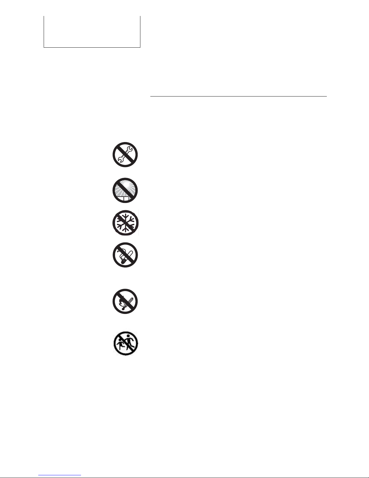
Do not open unit or fuel cartridges. Do not use force to
open cartridges and do not refill them. Any
modifications to the unit may affect safe operation, will
lead to a loss of license and will void the guarantee Use
only original EFOY equipment.
Do not store unit and fuel cartridges at temperatures
above 45° C. Do not operate at temperatures above 40°
C. Keep away from heat and direct sunlight.
Store the unit where there is no danger of freezing, or
use the automatic antifreeze feature.
Do not smoke when handling the unit or the fuel
cartridges.
Keep away from heat and open flame.
There is a danger of fire if methanol leaks out following
an accident, or if the unit or the fuel cartridge has been
damaged. Keep away from open fire and make sure
area is well ventilated. Small amounts of methanol
which may leak out will evaporate without leaving any
residue.
Keep unit and fuel cartridges (including empty or
partially filled cartridges) out of children’s reach.
Operate the unit only in accordance with instructions
and keep operating area well ventilated. Do not block
exhaust. Avoid inhaling exhaust fumes directly or for
prolonged periods of time.

1. Introduction
5
There is no risk of coming into contact with methanol
provided that you handle the unit and fuel cartridges in
accordance with instructions.
We are required by law to print the following notice.
Methanol is toxic if inhaled, ingested or if it comes into
contact with skin. Irreparable damage may occur if
inhaled, ingested or if it comes into contact with skin. In
the event of an accident or if nausea occurs, consult a
physician immediately. Be sure to bring the fuel cartridge
label or these instructions to the consultation. (A caution
concerning methanol can be found in the appendix.)
System exhaust may contain harmful components. Avoid
inhaling exhaust directly or for prolonged periods of time.
Use the exhaust hose to conduct exhaust gases to the
exterior.
Improper use or improper connection to other electrical
devices may result in damage.
In addition to these safety instructions, please observe
the passages in bold type. Otherwise, you may endanger
yourself and others.

1. Introduction
6
1.3
Normal Operation
The EFOY 600, EFOY 1200 and EFOY 1600 are automatic
charging devices for 12V lead batteries.
The unit may be used only to charge lead batteries that
conform to the specifications in Chapter 3.4, S. 12).
The specifications allow for solid-state operation (see
Chapter 3.4) on boats and motor vehicles. Operate only
with original-equipment EFOY fuel cartridges.
The unit is not intended for emergency medical power
generation, or for powering life-sustaining or agricultural
devices.
Do not operate unit if housing is damaged.
1.4 Declaration of Conformity
SFC Smart Fuel Cell AG, Eugen-Sänger-Ring 4, 85649
Brunnthal-Nord declares that the EFOY 600, EFOY 1200
and the EFOY 1600 conform to the European Community’s
89/336/EWG guidelines for electro-magnetic
compatibility. The following norms apply: DIN EN 61000-
6-1, DIN EN 61000-6-3
1.5 Seals of Approval
These units have been tested in accordance with ECE
Regulation No. 10 for electro-magnetic compatibility.
Operation in motor vehicles is permitted.
E 24
Approval number: E24 10R-020234

1. Introduction
7
1.6
Disposal
Packaging
Packaging protects your unit during shipping. All
materials used are environmentally compatible and
recyclable.
We recommend saving the packaging for eventual
winter storage.
Should you nevertheless wish to dispose of the
packaging, please do so properly.
Your dealer or your local recycling center can provide
information about proper disposal.
Danger of Suffocation!
Keep packaging away from children. Plastic
wrapping and cartons may cause suffocation.
Fuel Cartridges
Sort empty fuel cartridges with plastics. Dispose of
partly filled fuel cartridges in the same manner as
solvents or paint.
Old Units
Old units are still valuable! Proper disposal can yield
valuable raw materials while protecting the
environment.
Your dealer or the EFOY hotline:
Tel.: 0049 89 607 454-99
can advise you about returning old units.

2. Table of Contents
8
2. Table of Contents
1. Introduction 3
1.1 Foreword 3
1.2 Safety Information 4
1.3 Normal Operation 6
1.4 Declaration of Conformity 6
1.5 Seals of Approval 6
1.6 Disposal 7
2. Table of Contents 8
3. Configuration 9
3.1 Standard Equipment 9
3.2 Overview 9
3.3 Remote Control 10
3.4 Specifications 11
4. Installation 13
4.1 Space Requirements 13
4.2 Securing 15
4.3 Connecting the Exhaust Hose 16
4.4 Off-heat duct 17
4.5 Electrical Connections 18
4.6 Connecting the Remote Control 19
4.7 Select Language 21
5. Operation 22
5.1 Connecting the Fuel Cartridge 22
5.2 Automatic Operation 24
5.3 Switching on the Fuel Cell 25
5.4 Display Information 25
5.5 Remote Operation 27
5.6 Parallel Operation of Multiple Units 27
5.7 Switching Off the Fuel Cell 28
5.8 Automatic Antifreeze Feature 28
5.9 Storage 29
6. Maintenance 31
6.1 Service 31
6.2 Cleaning 31
7. Troubleshooting 32
7.1 Safety 32
7.2 Problems and Solutions 32
7.3 Problems without Error Messages 34
7.4 Changing the Fuse 35
7.5 Replacing Service fluid 36
8. Appendix 37
8.1 Accessories and Spare Parts 37
8.2 Output characteristic 39
8.3 Material safety data sheet methanol 40

3. Configuration
9
3. Configuration
3.1
Standard Equipment
The following is standard equipment:
unit
RC1 remote control with data line
FH 1 fuel-cartridge holder with belt
MP 1 mounting plate with belt
EH 1 exhaust hose (1.5 m)
Charge line
Service-Kit
UM1 user manual
3.2
Overview
1 Charge line connection
2 RC 1 remote-control connection
3 Data interface
4 G-fuse 250V 8A M, 5 x 20 mm
5 fuel-cartridge connection
6 connection for EH 1 exhaust hose and nozzle for
service fluid
7 cooling inlet (reverse)
8 warm-air outlet and connection for off-heat duct

3. Configuration
10
3.3
Remote Control
auto
reset
!
1 Display
2 Information button and language-selection button >>
3 On/Off button
4 Button for automatic operation auto
5 Yellow warning light “Please change fuel cartridge“
6 Red error warning light
7 Reset button reset

3. Configuration
11
3.4
Specifications
Performance
Product EFOY 600 EFOY 1200 EFOY 1600
Rating 25 W 50 W 65 W
Charge capacity 600 Wh/Day
(50 Ah/Day) 1200 Wh/Day
(100 Ah/Day) 1600 Wh/Day
(130 Ah/Day)
Nominal voltage 12 V 12 V 12 V
Charging current @ 12 V 2.1 A 4.2 A 5.4 A
Turn on threshold* Ubatt < 12.5 V Ubatt < 12.5 V Ubatt < 12.5 V
Cut off threshold* Ubatt >14.2 V and
Iout < 2.0 A Ubatt >14.2 V and
Iout < 2.0 A Ubatt >14.2 V and
Iout < 2.0 A
Required starting voltage > 10.8 V > 10.8 V > 10.8 V
Quiescent current requirement 15 mA 15 mA 15 mA
Methanol requirement 1.1 l/kWh 1.1 l/kWh 1.1 l/kWh
Compatible batteries 12 V rechargeable (lead-acid or lead-gel) batteries with 40 to
200 Ah capacity
General Specifications
Sound pressure level at 7 m 23 dB(A)
Dimensions (L x W x H) 43.5 x 20 x 27.6 cm
Weight 7.5 kg
Environmental conditions
Space requirement (L x W x H) 51 x 35 x 30 cm minimum
continual: 35°Inclination along the direct
axis temporary (<10 min): 45°
Inclination along the
quadrature axis continual: 20°
Operating temperature -20 to +40 °C
Start temperature +5 to +40 °C
Storage temperature +1 to +45 °C
* factory setting

3. Configuration
12
Instrumentation
Operation via remote control with four buttons and multilingual display
Electrical interface MNL 4-prong plug
Type Tyco Electronics AMP Universal Mate-N-Lok (Mfr. No.
350779)
Fuse G fuse 250V 8.0A M, 5 x 20 mm

4. Installation
13
4. Installation
Securely fasten unit and fuel cartridges when using on
board motor vehicles and boats.
Do not operate unit if there is danger of explosion.
Unit is not watertight. Make sure that no water can enter.
Keep unit and fuel cartridges away from children,
temperatures in excess of 45° C and direct sunlight.
4.1 Space Requirements
Please note when installing that operating temperature
ranges between –20° C and +40° C.
This unit generates heat, thus requiring ventilation.
Please take this into account when considering space
requirements.
Provide for a vent opening measuring at least 10 cm
across when installing. Use the off-heat duct (included) to
remove warm air.
Install only in upright position. Use the mounting plate
(included).
Make sure that the device does not exceed the maximum
inclination.
Inclination along the direct axis:
continual: 35°
temporary (<10min): 45°
Inclination along the quadrature axis:
continual: 20°

4. Installation
14
All electrical connections, the fill opening for service fluid
and the fuel cartridge should be easily accessible.
Install unit and fuel cartridge at the same level.
Make sure that the fuel cartridge is located within reach
of the connecting hose (30 cm) and that the hose is
neither kinked nor crushed.
The fuel-cartridge hose and the exhaust hose may not be
damaged. Do not substitute another hose for either of the
two.
Use only original-equipment EFOY hoses.
exhaust
electrical connection
Do not place the fuel cartridge in front of the air intake or
the exhaust!
Place fuel cartridges next to or in front of the unit as
illustrated.
Do not place any other objects such as reserve fuel
cartridges in front of intakes or the exhaust outlet.
4. Installation
15
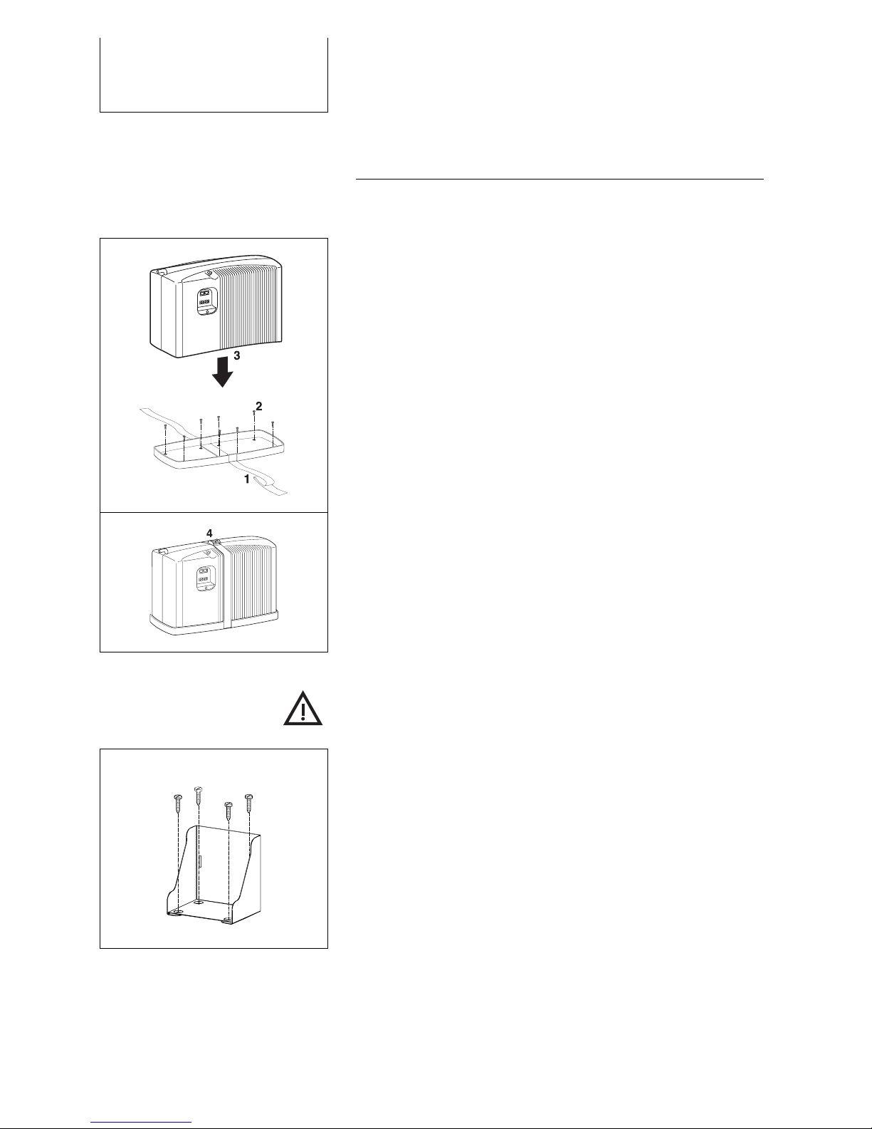
4.2 Securing
Securing the unit
Select a suitable location as described in Chapter 4.1,
paying attention to the dimensions in Chapter 3.4
Specifications.
1. Run the belt in the groove under the mounting plate.
2. Secure the mounting plate tightly to the desired
location. Use proper screws and dowels, if
necessary, so that the mounting plate cannot shake
loose in an accident, for example.
3. Place the unit onto the mounting plate.
4. Strap the unit tightly to the mounting plate.
Securing the fuel-cartridge holder
Keep fuel cartridge and reserve cartridges away from
children, heat and out of direct sunlight.
Select a suitable location for the fuel cartridge and
reserve cartridges as described in Chapter 4.1 “Space
requirements“.
Install device and fuel cartridge on the same level.
Secure the fuel-cartridge holder with four suitable
screws and dowels, if necessary, so that it does not
shake loose in an accident, for example.

4. Installation
16
4.3 Connecting the Exhaust Hose
The unit converts methanol and oxygen into water and
carbon dioxide. The process generates heat, which
together with water vapor, carbon dioxide and trace
amounts of methanol, must escape.
Attach the exhaust hose (included) to conduct by
products to the exterior.
Remove the cap from the exhaust port. Retain the
cap for winter storage or for possible returns.
Attach the exhaust hose (included) to the exhaust
port.
Feed the hose from the chassis to the exterior and
use a suitable sealant to seal the opening. The hose
may be shortened as needed.
Make sure the exhaust hose has no kinks or
blockage and that exhaust can escape freely.
Exhaust gasses contain moisture and may exceed 60°
C, thereby causing scalding. Exhaust byproducts may
contain injurious substances. Avoid inhaling exhaust
directly or for long periods of time.
At no time may siphoning occur in the hose. Make sure
that the hose is neither closed nor blocked.
The exhaust hose may not be longer than 50 cm in
order to prevent freezing in winter. The hose may be up
to 150 cm long for summer operation and during
transitional seasons.
Routing the exhaust hose
Up
Down
Avoid siphoning

4. Installation
17
4.4 Off-heat duct
The off-heat duct (included) extracts warm air so that the
unit can also be operated in close quarters.
12
3
1. Off-heat flange
2. Off-heat tube
3. Off-heat bow
Fasten the off-heat flange (1) to the unit using the pre-
sunk screw holes. Attach the off-heat tube (2) to the off-
heat bow and conduct the tube to the exterior. Should
the off-heat bow (3) not be needed, you can remove it
from the off-heat flange and attach the off-heat tube
directly to the flange.
Make sure that the hose is not crimped and that there is
no moisture or foreign objects inside. The hose may be
shortened as needed.
It may be necessary to use an external face plate to
protect the outlet.
4. Installation
18
4.5 Electrical Connections
All work should be carried out by qualified technicians in
accordance with technical regulations.
Improper connections or the use of wrong gauge wires
could result in fire.
All wires must be properly insulated and have adequate
voltage rating. All connections must be tight. The use of
uninsulated wires and contacts is not permitted.
Use the battery charging line (included). The circuit
connecting the battery must contain a fuse. Alternatively,
use the fuse (available as optional equipment) to connect
the battery.
Power lead
Sense lead
The battery charging cable consists of four leads that
must be connected to the battery as follows:
Power lead:
This lead carries current to the battery.
Sense lead:
This lead measures battery voltage.
To minimize current loss in the leads, the following
cross section is recommended, should the battery
charging cable, included as standard equipment, be
insufficient:
Length [m] min. cross section
< 5 m 2.5 mm²
5 – 10 m 4 mm²
10 – 15 m 6 mm²

4. Installation
19
unit
Strom –
Sense+
Sense–
–+
12 V Bleiakku
Strom +
+
–
–+
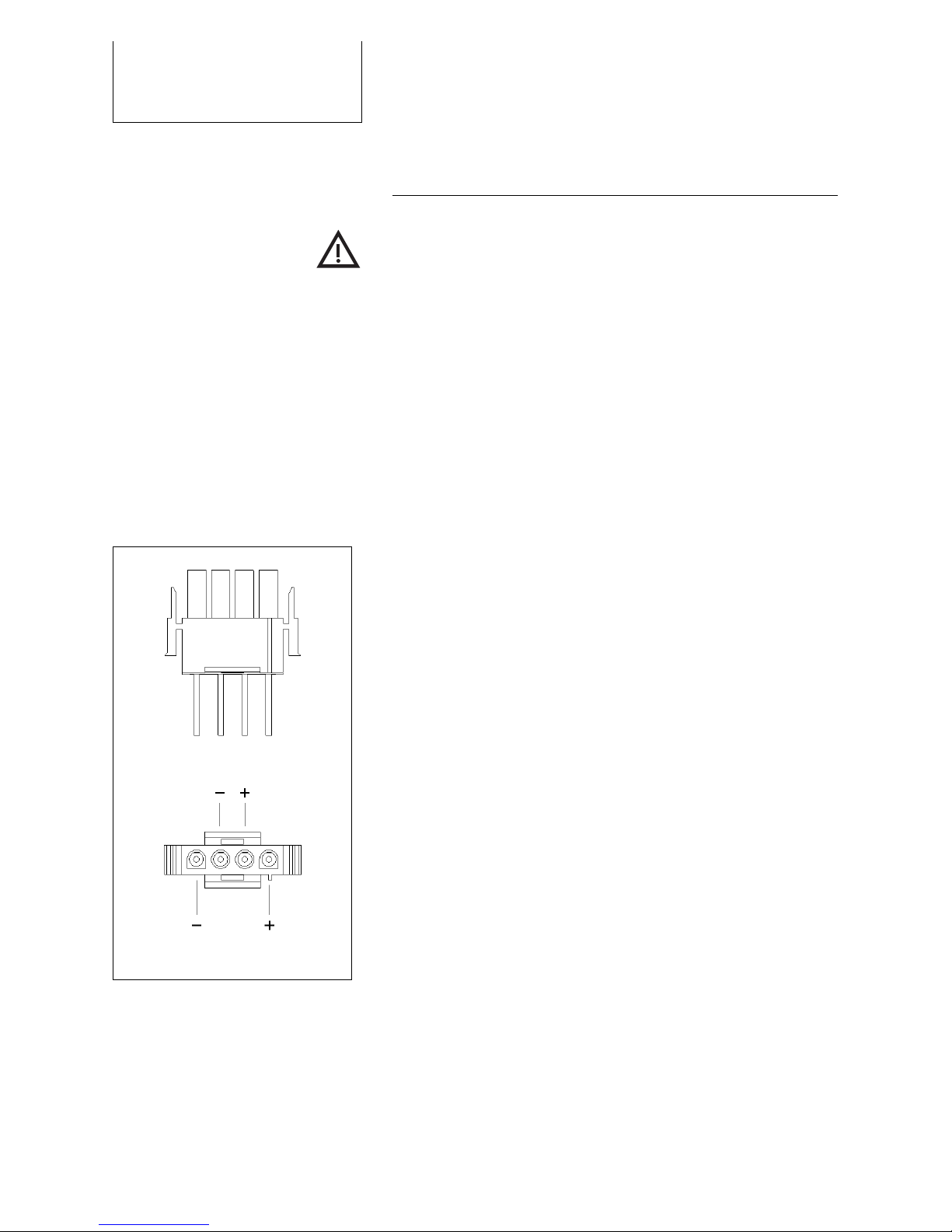
Make sure that the polarity is correct (see illustration).
Connect the positive wire + and the positive sensor cord
+ to the battery fuse. Then connect the battery fuse to
the battery’s positive terminal.
Then connect the negative wire – and the negative
sensor cord to the battery’s negative terminal.
Installation in recreational vehicles (RV)
See IM1 installation manual for RVs with Electroblock
(EBL).
4.6 Connecting the Remote Control
The remote control (1) displays the current status and
is used to control the device. Mount the panel where it
is easily accessible such as in the cockpit.
If installing the panel flush with the surface of the unit,
make sure that there is sufficient opening for the
electronic components behind the opening.
1 2
3 4
1 Control panel
2 Surface mount
3 Frame
4 Screws
Use templates for drilling and sawing when flush or
surface mounting (2). Use a drill to start the opening
and then cut out the rest of the opening with a keyhole
or compass saw.
12 V lead
battery
Then secure the control panel (1) with four suitable
screws (4) and place the frame (3) over the control
panel

4. Installation
20
Connect the control panel with the data line (included)
or with any commercially available network cable such
as a Cat. 5 patch cable.
Then insert the plug into the left socket on the unit
marked “Remote Control“.
Automatic
Standby
The display contains two lines with 16 characters
apiece.
The first line provides information as to the operating
mode selected:
Automatic
On
Off
It also provides information as to the language
selection. (See Chapter 4.7)
The second line provides information as to the
operating status:
Standby
Charging mode
Antifreeze mode
Shutting down
The second line also indicates operating parameters
such as charging current and such maintenance
parameters as “Please change fuel cartridge“.
Other manuals for 600
1
This manual suits for next models
2
Table of contents
Other EFOY Batteries Charger manuals


