EG4 6500 User manual

Version 2.0.0 - August 2022
6.5KVA 120V AC
6500 EX-48
EG4 Electronics
www.eg4electronics.com
1

Table of Contents
About This Manual
• Purpose & Scope 3
• Safety Notice 3
Introduction
• Features 4
• Basic System Architecture 4
• Product Overview 5
• Specifications 6
• Dry Contact Relay 9
Preparation & Installation
• Unpacking and Inspection 10
• Mounting the Inverter 11
• Battery Connection 12
• BMS Communications 13
• EG4 Battery Communications and Configuration 14
○ AC Input and Output Connections 17
○ PV Connections 19
• Parallel Inverter Connections 20
• Remote Display 27
• Final Assembly 27
Operating the Inverter/Charger
• Powering On/Off 29
• Display Panel 29
• Operating Modes 37
• System Settings 40
• USB Function Settings 51
Commissioning
• Single Phase 120V 54
• Split-Phase 240V 55
• Three Phase 56
Maintenance & Troubleshooting
• Cleaning and Care 58
• Troubleshooting Tables 59
Appendix I
• Fault Code Table 61
• Warning Code Table 63
• Lead Battery Chemistry Equalization 64
Appendix II
• Wifi Operation Guide 65
Appendix III
• UL Documentation 74
EG4 Electronics
www.eg4electronics.com
2

ABOUT THIS MANUAL
Purpose
This manual describes installation, commissioning, operation, and troubleshooting. Please read the
manual fully and carefully before installing and operating. Keep this manual for future use.
Scope
This manual provides basic safety and installation guidelines as well as information on tools and wiring.
SAFETY NOTICE
ATTENTION: The following contains important safety and operating instructions. Read
and keep this manual for future reference.
1. Before installing or using the unit, read all instructions and cautionary markings on the unit, the
batteries, and all appropriate sections of the manual.
2. CAUTION- Do not disassemble the unit. Take it to a qualified service center when service or repair
is required. Incorrect re-assembly may result in a risk of electric shock or fire.
3. To reduce risk of electric shock, shutdown and disconnect all wirings before attempting any
maintenance or cleaning. Turning off the unit alone will not reduce the risk of shock or injury.
4. CAUTION – Only qualified personnel can install this equipment.
5. NEVER charge a battery below specified minimum temperature; refer to the battery data sheet.
6. Wire size is critical for safe operation, and optimal performance of the equipment. Refer to a
accredited sizing resource or cable manufacturer specifications to meet inverter/charge requirements.
7. Use caution when working with metal tools on or around all systems and batteries. Risk of electrical
arcs and/or short circuiting of equipment can lead to severe injury and damage.
8. Strictly follow installation procedure when connecting and disconnecting AC or DC terminals. Refer to
INSTALLATION section of the manual for details.
9. The included breaker is not a guarantee of battery protection. Size and install the correct over current
protection for the batteries if not included with the product.
10. GROUNDING -This inverter/charger should be connected to a permanent grounded wiring system.
The grounding system must meet the Authority Having Jurisdiction (AHJ) requirements in your area.
11. NEVER short AC output and DC inputs. Do NOT connect to the grid with a shorted DC input.
12. Warning!! Only qualified service persons are able to service this device. If errors still persist after
following troubleshooting table, please contact your retailer for further assistance.
13. WARNING: Because this inverter is non-isolated, only three types of PV modules are acceptable:
Mono-crystalline, Polycrystalline with class A-rated, and CIGS modules. To avoid any malfunction, do
not connect any PV modules with possible current leakage to the inverter. For example, grounded PV
modules will cause current leakage to the inverter. When using CIGS modules, please be sure NOT to
ground.
14. CAUTION: DC breakers and surge protection on PV lines is recommended. Without breakers the
equipment is at higher risk of damage from sources such as surges and lighting strikes.
EG4 Electronics
www.eg4electronics.com
EG4 Electronics
www.eg4electronics.com
3

INTRODUCTION
This is a residential self consumption multi-function inverter, combining the functions of an inverter, solar
controller, and battery charger to offer uninterrupted power support in a single package. The
comprehensive LCD display offers user-configurable and easily-accessible button operations such as
battery charging current, AC or solar charging priority, and acceptable input voltage based on different
applications.
Configurable color with the built-in RGB LED bar
Built-in Wi-Fi for mobile monitoring (APP is required)
Supports USB On-the-Go function to easily upgrade firmware
Built-in anti-dust kit
Detachable LCD control module with multiple communication ports for BMS (RS485, CAN-BUS,
RS232)
Configurable input voltage tolerances for home appliances and personal computers via LCD control panel
Configurable AC/PV output usage timer and prioritization
Configurable AC/Solar charger priority via LCD control panel
Configurable battery charging current based on applications via LCD control panel
Compatible with the grid or generator power
Auto restart on AC reconnect
Overload / Over temperature / short circuit protection
Smart battery charger design for optimized battery performance
Basic System Architecture
The following illustration is an example of a basic application for this unit showing multiple inputs and
outputs. Please note an AC source may not be required for operation and is listed as an example only:
Generator or Utility
48V Battery
PV modules
Consult with a system installer and/or designer for other possible system design options
depending on the specific site requirements. System design is key to proper function and
performance and sites and systems vary greatly.
Figure 1 Basic PV System Overview
Features
EG4 Electronics
www.eg4electronics.com
EG4 Electronics
www.eg4electronics.com
4

1. LCD display
2. Status indicator
3. Charging indicator
4. Fault indicator
5. Function buttons
6. Power on/off switch
7. AC input connectors
8. AC output connectors (Load connection)
9. PV terminal
10. Battery connectors
11. Remote LCD module communication
12. Current sharing port
13. Parallel communication port
14. Dry contact
15. OTG-USB port as USB communication port and USB
function port
16. BMS communication port: CAN, RS-485 or RS-232
17. Output source indicators (refer to OPERATION/Operation
and Display Panel section for details) and USB function
setting reminder (refer to OPERATION/Function Setting for
the details)
18. RS-232 communication port for firmware updates from a
PC
19. RGB LED bar (refer to LCD Setting section for the details)
Port
EG4 Electronics
www.eg4electronics.com
Product Overview
EG4 Electronics
www.eg4electronics.com
5
Installation Note: The EG4 6.5KW unit is a parallel capable model. For parallel 120V, 240V Split-phase, or
3-phase installation diagrams and instructions, please check the
Parallel Connections
and
Commissioning
sections of the manual for further details.

SPECIFICATIONS
Table 1 Line Mode Specifications
MODEL
6.5KW
Input Voltage Waveform
Sinusoidal (utility or generator)
Nominal Input Voltage
120Vac
Low Loss Voltage
90Vac±7V (UPS)
80Vac±7V (Appliances)
Low Loss Return Voltage
100Vac±7V (UPS);
90Vac±7V (Appliances)
High Loss Voltage
140Vac±7V
High Loss Return Voltage
135Vac±7V
Max AC Input Voltage
150Vac
Max AC Input Current
60A
Nominal Input Frequency
50Hz / 60Hz (Auto detection)
Low Loss Frequency
40±1Hz
Low Loss Return Frequency
42±1Hz
High Loss Frequency
65±1Hz
High Loss Return Frequency
63±1Hz
Output Short Circuit Protection
Line mode: Circuit Breaker (70A)
Battery mode: Electronic Circuits
Efficiency (Line Mode)
>95% ( Rated R load, battery full charged )
Transfer Time
10ms typical (UPS);
20ms typical (Appliances)
Power Limitation
Input Voltage
Output Power
Rated Power
50%
Power
80V110V140V
EG4 Electronics
www.eg4electronics.com
EG4 Electronics
www.eg4electronics.com
6

Table 2 Inverter Mode Specifications
MODEL 6.5KW
Rated Output Power 6,500W
Output Voltage Waveform Pure Sine Wave <3% THD
Output Voltage Regulation 120Vac±5%
Output Frequency 60Hz or 50Hz
Peak Efficiency 91%
Overload Protection 100ms@≥205% load;5s@≥150% load; 10s@110%~150% load
Surge Capacity 13,000W
Nominal DC Input Voltage 48.0Vdc
Cold Start Voltage 46.0Vdc
Low DC Warning Voltage
@ load < 20% 46.0Vdc
@ 20% ≤ load < 50% 42.8Vdc
@ load ≥ 50% 40.4Vdc
Low DC Warning Return Voltage
@ load < 20% 48.0Vdc
@ 20% ≤ load < 50% 44.8Vdc
@ load ≥ 50% 42.4Vdc
Low DC Cut-off Voltage
@ load < 20% 44.0Vdc
@ 20% ≤ load < 50% 40.8Vdc
@ load ≥ 50% 38.4Vdc
High DC Recovery Voltage
64.0Vdc
High DC Cut-off Voltage 66.0Vdc
DC Voltage Accuracy +/-0.3V@ no load
THDV <5% for linear load,<10% for non-linear load @ nominal voltage
DC Offset ≦100mV
EG4 Electronics
www.eg4electronics.com
EG4 Electronics
www.eg4electronics.com
7

Table 3 Charge Mode Specifications
Utility Charging Mode
MODEL 6.5KW
Charging Current (UPS)
@ Nominal Input Voltage 120A
Bulk Charging
Voltage
Flooded
Battery 58.4Vdc
AGM / Gel
Battery 56.4Vdc
Floating Charging Voltage 54.0Vdc
Overcharge Protection 66.0Vdc
Charging Algorithm 3-Step
Charging Curve
Time
Battery Voltage, per cell Charging Current, %
100%
50%
Bulk
(Constant Current)
Absorption
(Constant Voltage)
Maintenance
(Floating)
Current
Voltage
T1 = minimum 10mins, maximum 8hrs
2.43Vdc (2.35Vdc)
2.25Vdc
Solar Input
MODEL 6.5KW
Rated PV 8000W
Max. PV Array Open Circuit
Voltage 500Vdc
PV Array MPPT Voltage Range 90Vdc~450Vdc
Max. Input Current Draw 18A x 2
Start-up Voltage 80V +/- 5Vdc
Power Limitation
PVCurrent
MPPTtemperature
18A
9A
75°85°
EG4 Electronics
www.eg4electronics.com
EG4 Electronics
www.eg4electronics.com
8

Table 4 General Specifications
MODEL 6.5KW
Safety Certification UL 1741 Certificate by TUV
Operating Temperature Range -10°C to 40°C
Storage temperature -15°C~ 60°C
Humidity 5% to 95% Relative Humidity (Non-condensing)
Dimension
(D*W*H), in 58.03in x 170.2in x 226.6in (244.3in) (with extension box)
Net Weight, lbs 40.5lbs
Table 5 Parallel Specifications (Parallel model only)
Max parallel numbers
6
Circulation Current under No Load Condition
Max 2A
Power Unbalance Ratio
<5% @ 100% Load
Parallel communication
CAN
Transfer time in parallel mode
Max 50ms
Parallel Kit
YES
Note: Parallel feature will be disabled when only PV power is available
EG4 Electronics
www.eg4electronics.com
Dry Contact Relay
There is one dry contact (3A/250VAC) available on the bottom of the inverter display. It can be used to
deliver signal to external device when battery voltage reaches a set warning level.
Unit Status Condition
Dry contact port:
NC & C NO & C
Power Off Unit is off and no output is powered. Close Open
Power On
Output is
powered
from Battery
power or
Solar energy.
Program 01
set as USB
(utility first)
or SUB (solar
first)
Battery voltage < Low DC
warning voltage Open Close
Battery voltage > Setting
value in Program 13 or
battery charging reaches
floating stage
Close Open
Program 01 is
set as SBU
(SBU priority)
Battery voltage < Setting
value in Program 12 Open Close
Battery voltage > Setting
value in Program 13 or
battery charging reaches
floating stage
Close Open
EG4 Electronics
www.eg4electronics.com
9
PREPERATION & INSTALLATION:
Unpacking and Inspection
Before installation, please inspect the unit. Be sure that nothing inside the package is damaged. The
following items should be included in the package:
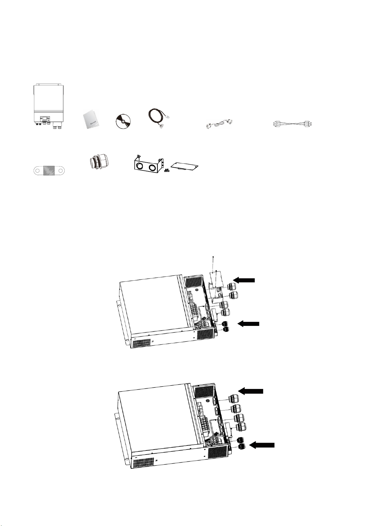
Inverter unit Manual software CD RS-232 cable Parallel communication cable Current sharing cable
DC Fuse Cable gland x 4 pcs Extension Box Kit
Installation of Battery Wiring Extension Box, Cable Glands, and
Conduit Fittings 1/2" or 3/4"
Install two (2) cable glands or conduit fittings on the extension box, then fix the extension box on the
rear panel of the inverter.
Note: Installation of the battery wiring extension box is necessary for UL
conformity. If UL conformity is not required in your region, it is sufficient to only install the cable glands
(Graphic 2) shown below.
Fig.1 6500 with Extension Box
Fig.2 6500 without Extension Box
EG4 Electronics
www.eg4electronics.com
EG4 Electronics
www.eg4electronics.com
10

Before connecting all wirings, please take off bottom cover by removing the five screws. When
removing the bottom cover, be carefully to remove three cables as shown below.
Mounting the Inverter
Consider the following points before selecting an install location:
⚫Do not mount the inverter on flammable materials.
⚫Mount on a solid surface.
⚫For optimal operation, install in a location where ambient
temperature stays between 0℃ - 40℃ (32℉ - 104℉).
⚫Mount the unit in a vertical position and following the clearance
guide for proper cooling and longevity.
⚫Follow clearance guidelines shown to the right diagram to
guarantee sufficient heat dissipation and clearance for conduit
and wire runs.
⚫Ensure mounting location follow your local authority having
jurisdiction rules on working space requirements. For the US
market, refer to the NEC version adopted by your AHJ.
Mount the unit using the 4 holes denoted below. M5 (#10 Imperial) screw/bolt diameter is recommended.
SUITABLE FOR MOUNTING ON CONCRETE OR OTHER NON-COMBUSTIBLE SURFACE ONLY.
EG4 Electronics
www.eg4electronics.com
EG4 Electronics
www.eg4electronics.com
11

Battery Connection
CAUTION: For safe operation and regulation compliance, DC overcurrent protection and means of
disconnect should be installed between the battery and inverter. In many cases individual battery units
will come with breakers, however overcurrent and disconnecting means should be added for banks of
multiple batteries. Please refer to the typical amperage in table below for required fuse or breaker size.
WARNING! All wiring design and install must be performed by qualified personnel.
WARNING! For safe and efficient operation use the appropriate cable size for
battery connections. To reduce risk of injury and equipment damage, use properly
rated cable and terminal sizes.
Recommended battery cable and terminal size:
Model Typical
Amperage
Battery
capacity
Minimum
Wire Size
Cable
mm2
Ring Terminal Torque
value
Dimensions
D (mm) L (mm)
6.5KW 153A 250AH 1*2/0AWG 67 8.4 47 5 Nm
Please follow the below steps for battery connection:
1. Insert the ring connection end of the battery cable through the cable gland of the inverter.
2. Ensure the bottom (flat) side of the cable ring termination is fully seated on the inverter battery terminals.
3. Tighten the terminal nuts to a torque of 5 Nm (3.6ft lbs). Make sure polarity at both the battery and the
inverter/charge is correctly connected and ring terminals are tightly screwed to the battery terminals.
WARNING: Shock Hazard
Arc and shock hazards are present! Do not touch uninsulated wires, and use caution when
making connections. Ensure all equipment is turned off, use proper safety equipment, and follow
best practices.
CAUTION!! Do not place anything between the inverter terminal and the battery cable ring
connector. Overheating and equipment damage can occur.
CAUTION!! Do not apply anti-oxidant substance on the terminals.
CAUTION!! Before making the final DC connection or powering on DC circuits ensure both
positive and negative cable runs are correctly connected throughout the system. Incorrect or loose
connections will damage equipment and pose electrical shock, arc, and fire risks.
Ring terminal:
EG4 Electronics
www.eg4electronics.com
EG4 Electronics
www.eg4electronics.com
12

BMS Communication Installation- EG4-LL
1. Introduction
When connecting to LFP battery, it is recommended to purchase a custom-made RJ45 communication
cable. Please check with your dealer or integrator for details.
This custom-made RJ45 communication cable delivers information and signal between lithium battery and
the inverter. The information is listed below:
⚫Re-configure charging voltage, charging current and battery discharge cut-off voltage according to the
lithium battery parameters.
⚫Starting and stopping of charging is based on the batteries SOC (State Of Charge)
2. Pin Assignment for BMS Communication Port
Definition
PIN 1
RS232TX
PIN 2
RS232RX
PIN 3
RS485B
PIN 4
NC
PIN 5
RS485A
PIN 6
CANH
PIN 7
CANL
PIN 8
GND
EG4 Electronics
www.eg4electronics.com
13
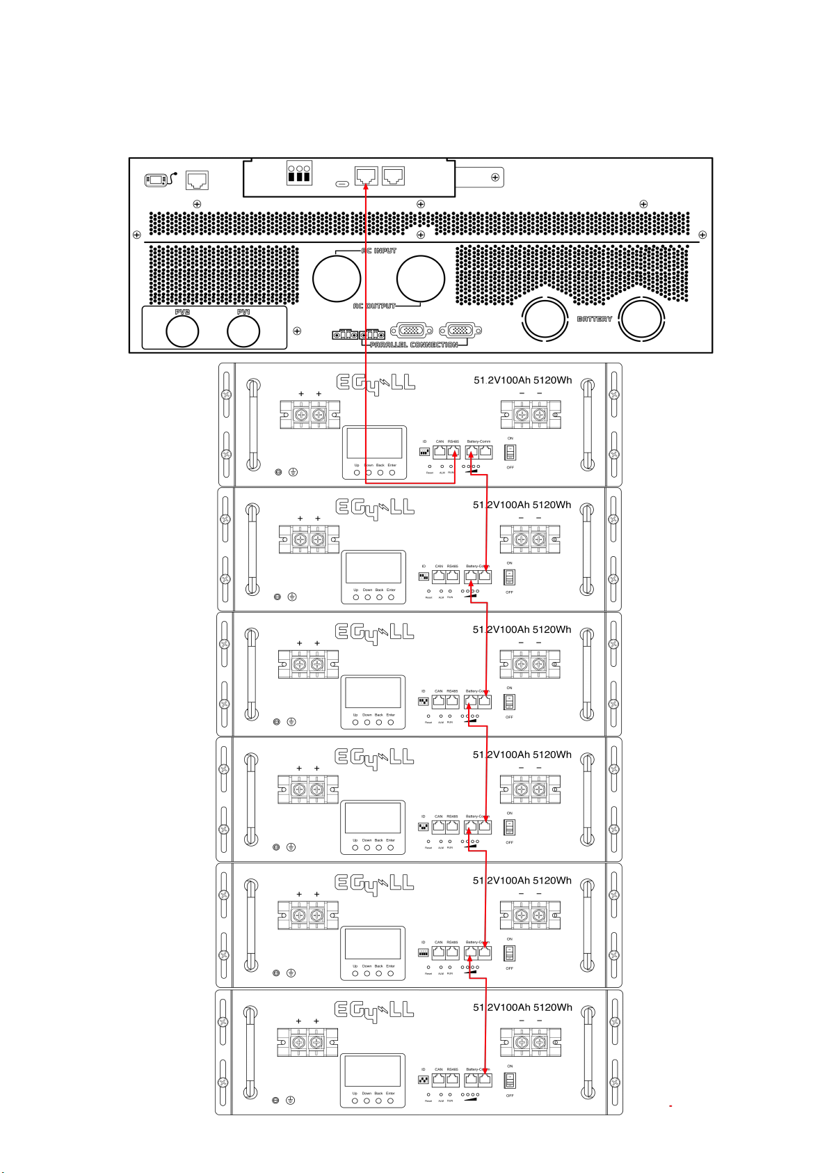
Battery Networking- EG4-LL
Using the 1ft RS485 cable interconnect your batteries as illustrated in the
diagram below.
EG4 Electronics
www.eg4electronics.com
14

Battery Networking-LiFePower4
Using the 1ft RS485 cable interconnect your batteries as illustrated in the
diagram below.
EG4 Electronics
www.eg4electronics.com
15

Settings for EG4 Lithium Batteries- Master/Slave
1). Dip Switch: There are 4 Dip Switches which set different baud rates and battery
group addresses. If switch position is turned to the “OFF” position, it means “0”. If
switch position is turned to the “ON” position, it means “1”.
•Dip 1, 2, and 3 are in the
“ON” position*on = down
•Dip 4 is in the "OFF"
position*off = up
•The 1-3 "ON" & 4 "OFF"
configuration is to indicate
Master battery status and
is reserved for
communications with the
inverter.
•A Max of 16 batteries can
communicate in a single
battery bank using
different dipswitch
addresses.
EG4-LL Battery
•Dip 1, 2, 3, and 4 are in the
“OFF” position*off = down
•The ALL "OFF" position is to
indicate the Master battery
status and is reserved for
communications with the
inverter
•A Max of 16 batteries can
communicate in a single
battery bank.
EG4-LifePower4 Battery
Please Note: If you change the dipswitches, you must power cycle the batteries
for the BMS to recognize the new dipswitch address.
2). Installation
Step 1. Use the RS485 cable to connect the inverter and Lithium battery as Fig 1.
Step 2. Switch on the battery breaker/s.
Step 3. Turn on the inverter.
Step 4. Select battery type as “EG4” in LCD program 5 for the Master inverter. For other paralleled
inverters, set to "USE".
If communication between the inverter and battery is successful, the battery icon on LCD display will flash
EG4 Electronics
www.eg4electronics.com
16
NOTE:
For EG4-LL ensure the red power switch is set to "ON" as well as the breaker.
NOTE:
Even with the EG4 batteries having built-in breakers, a minimum 150A in line breaker is required, and a 200A
in line breaker is recommended.
NOTE:
Refer to each battery manual for setting master and follower battery address settings.

AC Input/Output Connections
CAUTION!! Install a breaker at the source of the AC input power source per requirements of authority
having jurisdiction. Ensure the AC source circuit is properly rated for the inverter/charger load
specification.
CAUTION!! There are two terminal blocks with “IN” and “OUT” markings. Do NOT reverse the input and
output connections. Ensure Line, Neutral, and Ground are wired to the correct terminals.
WARNING! All wiring must be performed by a qualified personnel.
WARNING! It is very important for system safety and efficient operation to use appropriate cable for AC
input connection. To reduce risk of injury and equipment damage, use properly sized cables according to local
jurisdiction and electrical code/requirements.
Suggested cable requirement for AC wires
Model Gauge Torque Value
6.5KW 4 AWG Max 1.4~ 1.6Nm
Follow the below steps to connect the AC input and output:
1. Before making AC input/output connection, be all power sources are off.
2. Remove 10mm (3/8in) wire insulation from the ground wires. Remove 7mm (~1/4in) of wire insulation
from the Line and Neutral conductors. Ensure no conductor is exposed beyond terminal block, paying
special attention to possible stray wire strands.
3. Fix two cable glands into input and output sides.
4. Insert AC input wires according to polarities indicated on terminal block and tighten the terminal screws. Be
sure to connect PE protective conductor ( ) first.
L→LINE(Black for Line 1)(Red for Line 2 in 120/240 split-phase configuration)
N→Neutral (White or Gray)
WARNING:
Ensure all AC sources remain off and all loads are turned off at the breakers before continuing with the
wiring process. Confirm AC source is off with multi-meter or non-contact voltage pen/tester.
EG4 Electronics
www.eg4electronics.com
17
Ground (Green or Green with Yellow stripe)

5. Connect the AC output wires according to labels printed on the case above the terminal blocks.
Connect the ground wire first ( ).
Ground (Green or Green with Yellow stripe)
L→LINE (Black for Line 1)(Red for Line 2 in 120/240 split-phase configuration)
N→Neutral (White or Gray)
6. Make sure the wires are properly connected and the terminal blocks are torqued to spec.
CAUTION: Appliances with heavy start and run demands, such as air conditioners, require
special consideration. For many air conditioners for example, at least 2~3 minutes to restart
can be required to allow enough time to balance refrigerant gases. If a power outage occurs and
recovers in a short time, it may cause damage to connected appliances. To prevent damage,
please check with the manufacturer of the appliance to see if it is equipped with a time-delay function
or soft-start feature before installation. Overload of the inverter/charger may trigger a fault leading
to sudden loss of AC output power, which may cause damage to appliances with motors/compressors.
CAUTION: Important
Connect AC wires to the correct terminals. If L and N wires are reversed, it will cause a
short-circuit and damage the equipment and loads connected to the system.
EG4 Electronics
www.eg4electronics.com
18

i. Remove 10 mm (3/8in) of insulation for positive
and negative conductors.
ii. Check correct polarity of connection cable from
PV modules and PV input connectors at the
disconnect. Connect positive pole (+) of
connection cable to positive pole (+) of PV input
connector. Connect negative pole (-) of connection
cable to negative pole (-) of PV input connector.
Step 3: Step 3: Make sure the wires are fully
inserted and the terminals are torqued to spec.
CAUTION! Ensure no wire strands are exposed
outside of the terminals blocks. No copper of the
conductions should be visible.
It is highly recommended to use red PV wire for
positive and black PV wire for negative to
reduce risk of reversing polarity in the system.
PV Connections
CAUTION: Before connecting PV modules/strings, install separate DC circuit breakers or a means of
disconnect paired with properly sized fuses between inverter and PV array/s. DO NOT work with or
connect live PV conductors to the unit. Ensure all exposed conductors are safely disconnected from
the power source.
NOTE: Use a 600VDC/30A rate circuit breaker. DC rated breakers must be used. The over voltage
category of the PV input is II. Please follow the steps below to implement PV module connection.
Step 1: Check the voltage of the PV modules/strings; ensure open circuit voltage (Voc) is designed to
never exceed the units rating (500V DC). This unit is equipped with two PV MPPT string inputs. Ensure
the maximum operating amperage (Imp) of each PV input is 18A or less. When using Rapid Shut Down
equipment refer to the RSS manufacturer's specifications for per-device and per-string ratings.
Step 2: Disconnect the circuit breaker and switch off the DC disconnect. Follow wiring process below.
CAUTION: Exceeding the maximum input voltage can destroy the unit! Check the system before wire connections.
WARNING: Because the inverter/charger is non-isolated, only three types of PV modules are
acceptable: monocrystalline and polycrystalline with class A-rated and CIGS modules.
To avoid malfunction, do not connect PV modules with possible current leakage. For example, grounded
PV modules will cause current leakage to the inverter. When using CIGS modules, please be sure NOT to
ground.
CAUTION: It is required to use a PV surge protection device. Damage to the inverter can occur from
surges such as lightning or short circuiting.
WARNING!
Open circuit Voltage (Voc of PV strings must not exceed the maximum PV array open circuit voltage of the
inverter. Check for environmental impacts on Voc, such as temperature in accordance to the module
manufacturers data sheet and reliable weather data for the installation location.
Voltage at Maximum Power (Vmp) of PV strings must be higher than the start-up voltage.
EG4 Electronics
www.eg4electronics.com
19

EG4 Electronics
www.eg4electronics.com
Parallel Inverter Connections
1. Introduction
This model of inverter is a 120V Single-phase unit able to operate in parallel with multiple other units. The
parallel function can be used to support multiple electrical system types, including multi-inverter Single-phase,
240 Split-phase, or 3-phase.
ATTENTION: Carefully review the paralleling requirements, specifically the current sharing cable connection
tables and parallel settings.
Battery Bank Considerations:
When designing the system, ensure the battery bank of the system is able to support both the potential max
load/s and constant load. Multiple inverters meeting a high load requirement with an undersized battery bank
will result in a system shutdown and potentially damage equipment.
Recommended Battery Sizing:
Inverters per System 2 3 4 5 6
Battery Capacity (48V) 200AH 300AH 400AH 600AH 600AH
WARNING! All inverters of a system must share the same battery bank. Ensure all batteries are connected to
common bus bars, with equal cable lengths between both the batteries/bus and inverter/bus connections.
2. Parallel Connections for 120V Single-phase:
Communication Connection
2
1
AC connections are the same for units 3-6.
EG4 Electronics
www.eg4electronics.com
•Inverter 1 Port A → Inverter 2 Port A
•Inverter 1 Port B → Inverter 2 Port B
Current Sharing Cables - configuration will be
noted on each diagram with dashed lines (green
when printed in color) in the following format:
•Inverter X Port A → Inverter X Port A
•Inverter X Port B → Inverter X Port B
WARNING: Damage to the inverters can occur
if current sharing cables are incorrectly
installed.
See Split-phase and 3-phase communication
connection guides for specifics.
EG4 Electronics
www.eg4electronics.com
20
Table of contents
Other EG4 Inverter manuals


Popular Inverter manuals by other brands


BARRON
BARRON EXITRONIX Tucson Micro Series installation instructions

Baumer
Baumer HUBNER TDP 0,2 Series Mounting and operating instructions

electroil
electroil ITTPD11W-RS-BC Operation and Maintenance Handbook

Silicon Solar
Silicon Solar TPS555-1230 instruction manual

Mission Critical
Mission Critical Xantrex Freedom SW-RVC owner's guide

HP
HP 3312A Operating and service manual


