Eizo CuratOR SC430-PTR User manual

Important
Please read this “Instructions for Use” carefully to familiarize
yourself with safe and effective usage.
Please retain this manual for future reference.
•For the latest product information including the “Instructions for
Use”, refer to our web site :
www.eizo-or.com
4K Surgical Field Camera System
Instructions for Use
English

SAFETY SYMBOLS
This manual and this product use the safety symbols below. They denote critical information. Please read
them carefully.
WARNING
Failure to abide by the information in a
WARNING may result in serious injury
and can be life-threatening.
CAUTION
Failure to abide by the information in a
CAUTION may result in moderate injury and/or
property or product damage.
Indicates a warning or caution. For example, indicates an “electrical shock” hazard.
Indicates a prohibited action. For example, means “Do not disassemble”.
Indicates a mandatory action. For example, means “Ground the unit”.
Thisproducthasbeenadjustedspecicallyforuseintheregiontowhichitwasoriginallyshipped.If
operatedoutsidethisregion,theproductmaynotperformasstatedinthespecications.
No part of this manual may be reproduced, stored in a retrieval system, or transmitted, in any form or by
any means, electronic, mechanical, or otherwise, without the prior written permission of EIZO Corporation.
EIZOCorporationisundernoobligationtokeepanysubmittedmaterialorinformationcondentialunless
prior arrangements are made pursuant to EIZO Corporation’s receipt of said information. Although every
effort has been made to ensure that this manual provides up-to-date information, please note that EIZO
productspecicationsaresubjecttochangewithoutnotice.
2

PRECAUTIONS
IMPORTANT
• Thisproducthasbeenadjustedspecicallyforuseintheregiontowhichitwasoriginallyshipped.
Iftheproductisusedoutsidetheregion,itmaynotoperateasspeciedinthespecications.
• To ensure personal safety and proper maintenance, please read carefully this section and the
caution statements on the product.
Location of the Caution Statements
Bottom of the CCU
Symbols on the unit
Symbol This symbol indicates
Power switch: Touch to turn the product’s power on or off.
Alternating current
Direct current
Alerting to electrical hazard
CAUTION: Refer to “SAFETY SYMBOLS” (page 2).
WEEE marking: Product must be disposed of separately; materials may be
recycled.
CE marking
English
3
PRECAUTIONS

WARNING
If the unit begins to emit smoke, smells like something is burning, or makes strange noises,
disconnect all power connections immediately and contact your EIZO representative for advice.
Attemptingtouseamalfunctioningunitmayresultinre,electricshock,orequipmentdamage.
Do not disassemble or modify the unit.
Openingthecabinetormodifyingtheunitmayresultinre,electricshock,orburns.
Referallservicingtoqualiedservicepersonnel.
Donotattempttoservicethisproductyourselfasopeningorremovingcoversmayresultinre,electric
shock,orequipmentdamage.
Keep small objects or liquids away from the unit.
Small objects accidentally falling through the ventilation slots into the cabinet or spillage
intothecabinetmayresultinre,electricshock,orequipmentdamage.Ifanobjector
liquidfalls/spillsintothecabinet,unplugtheunitimmediately.Havetheunitcheckedby
aqualiedserviceengineerbeforeusingitagain.
Properly install the product at a durable and stable place.
Install the product at a place that is strong enough to withstand the weight in accordance with the Instructions
forUse.Iftheunitisinstalledincorrectly,itmaydroporfallover,resultinginpersonalinjuryorequipment
damage. If the unit falls, disconnect the power immediately and ask your local EIZO representative for
advice.Donotcontinueusingadamagedunit.Usingadamagedunitmayresultinreorelectricshock.
Use the unit in an appropriate location.
Otherwise,re,electricshock,orequipmentdamagemayresult.
• Do not place outdoors.
• Do not place in any form of transportation (ships, aircraft, trains, automobiles, etc.).
• Do not place in dusty or humid environments.
• Do not place in locations where water may be splashed on the screen (bathrooms, kitchens,
etc.)
• Do not place in locations where smoke or steam come in direct contact with the screen.
• Donotplacenearheatgeneratingdevicesorhumidiers.
• Do not place in locations where the product is subject to direct sunlight.
• Donotplaceinenvironmentswithammablegas.
• Donotplaceinenvironmentswithcorrosivegases(suchassulfurdioxide,hydrogensulde,
nitrogen dioxide, chlorine, ammonia, ozone, etc.)
• Do not place in environments with dust, components that accelerate corrosion in the
atmosphere (such as sodium chloride and sulfur), conductive metals, etc.
To avoid danger of suffocation, keep the plastic packing bags away from babies and children.
Use the enclosed power cord and connect to the standard power outlet in your country.
Besuretousewithintheratedvoltageofthepowercord.Otherwise,reorelectricshockmayresult.
Powersupply:100-240Vac50/60Hz
Use the enclosed AC adapter.
TheenclosedACadapter(AHM100PS24)isforusewiththisproductonly.DonotusetheACadapterwith
otherequipment.DonotuseanACadapterdesignedforotherdeviceswiththisproduct.
ConnectingtopowersourcesthatdonotmatchthepowerratingsoftheACadaptermayresultinreor
electric shock.
4PRECAUTIONS

WARNING
To disconnect the power cord or adapter power cable, grasp the
plugrmlyandpull.
Tuggingonthecordorcablemaydamageitandresultinreorelectric
shock.
The equipment must be connected to a grounded main outlet.
Failuretodosomayresultinreorelectricshock.
Use the correct voltage.
• Theunitisdesignedforusewithaspecicvoltageonly.Connectiontoanothervoltagethanthatspeciedinthis
“InstructionsforUse”maycausere,electricshock,orequipmentdamage.
Powersupply:100-240Vac50/60Hz
• Donotoverloadyourpowercircuit,asthismayresultinreorelectricshock.
Handle the power cord and AC adapter with care.
HandlethepowercordandACadapterwithcare.
Do not place heavy objects on, pull or tie the power cord or the AC adapter. Using a
damagedcordorACadaptermayresultinreorelectricshock.
The operator should not touch the patient while touching the product.
This product has not been designed to be touched by patients.
Never touch the plug, AC adapter or power cord during a thunderstorm.
Touching them may result in electric shock.
Handle the batteries for the remote control with care.
Notdoingsomayresultinbatteryexplosion,liquidleakage,orburns.
• Do not disassemble, heat, short-circuit, or immerse the provided batteries in water.
• Install/change batteries in a correct way.
• When replacing batteries, use ones of the same type and model.
• When replacing batteries, replace all of them at the same time with new batteries of the same brand and type.
• Insert batteries with correct direction of the plus (+) and minus (-) sides.
• Do not use the battery with coating damaged.
• Dispose of your battery in a designated disposal area.
• In case of swallowing a battery, seek medical attention immediately.
English
5
PRECAUTIONS

CAUTION
Check the operational state before use.
Begin use after ensuring that there are no problems with the displayed image.
Securelyxcables/cordsthathaveaxingfeature.
If the cables and cords are not secured in place, they may become disconnected, leading to an interruption
of the operation.
Handle with care when carrying the unit.
Disconnect the power cord and cables when moving the unit. Moving the unit with the power cord or cables
attached is dangerous and may result in injury.
Do not block the ventilation slots on the cabinet.
• Do not place any objects on the ventilation slots.
• Donotinstalltheunitinaplacewithpoorventilationorinadequatespace.
• Do not use the unit laid down or upside down.
Blockingtheventilationslotspreventsproperairowandmayresultinre,electric
shock,orequipmentdamage.Metalpartswillalsobecomehot,leadingtoariskofburn
injury.
Do not touch the plug or AC adapter with wet hands.
Doing so may result in electrical shock.
Use an easily accessible power outlet.
This is to facilitate disconnecting the power in case of a problem.
The AC adapter becomes hot during use.
• Do not cover or place anything on top of the AC adapter. Do not place the AC adapter on top
of things that trap heat such as carpets, blankets, etc. Keep the AC adapter away from direct
sunlightandheatsources.Failuretodosomayresultinre.
• Before moving the product, be sure to turn off the power switch, disconnect the power plug
from the power outlet, and wait until it has cooled completely.
Do not suspend the AC adapter in midair.
Usingtheadapterwhileitishangingsuspendedmayresultinreorelectricalshock.
Do not place the AC adapter in a vertical orientation.
Otherwise,dustorwatermayentertheadapterandmayresultinreorelectricalshock.
See page 23 for details.
Do not apply impact to the product or drop it from a height.
Usingtheadapterafterithasbeensubjectedtoimpactmayresultinreorelectrical
shock.
Regularly wipe dust off from the power plug and the vent area.
Dust,water,oroilontheplugmayresultinre.
Unplug the unit before cleaning it.
Cleaning the unit while it is plugged into a power outlet may result in electric shock.
Ifyouplantoleavetheunitunusedforanextendedperiodoftime,disconnectthepowerplugfrom
the wall socket after turning off the power switch for safety and power conservation.
6PRECAUTIONS

About This Product
Intended Use
Thisproductisintendedtobeusedforcapturingtheoperativeeld.
Attention
• This product may not be covered by warranty for uses other than those described in this manual.
• Thespecicationsstipulatedinthismanualareonlyapplicablewhentheenclosedpowercordisused.
• Onlyuseoptionalproductsmanufacturedorspeciedbyuswiththisproduct.
Precautions for Use
• Condensationmayformonthesurface,lens,NDlter,ortheinteriorpartsofthisproductwhenthe
product kept at a cold temperature is brought into a room temperature, when the room temperature
suddenly rises, or when the product is moved to a room warmer than where it was placed. In that case,
do not turn the product on. Instead wait until the dew condensation disappears, otherwise it may cause
some damage to the product.
• Thefollowingphenomenaobservedonthecapturescreenarenotdefects.Thephenomenaareunique
to the CMOS imaging elements.
- White spots
CMOS imaging elements are known to generate small white spots on the screen in rare instances due to cosmic
rays, etc. This occurs due to the characteristics of CMOS. It is not a malfunction of the product. Note that such
white spots are likely to appear under the following conditions:
• Usages in a high-temperature environment
• Usages with increased gain
• Usages with slower shutter speed
- Aliasing distortion
When capturing subtle patterns or lines, the patterns or colors may appear differently from the original objects.
Cautions for Network Use
The following risks apply when connecting to a network.
• Unauthorized operation of this product by a malicious third party.
• Interference or shut-down of this product by a malicious third party.
Theuserisresponsibleforimplementingadequatenetworksecuritymeasures,includingthemeasures
described below, in order to prevent the aforementioned described risk.
• Usethisproductwithasafety-ensurednetworkbyusingarewallorothernetworksecuritysystem.
• Check for communication problems in advance.
English
7
About This Product

Cleaning
Periodic cleaning is recommended to keep the product looking new and to prolong its operation lifetime.
Gently wipe off any dirt attached to the product with a soft piece of cloth moistened with a small amount
of water or one of the chemical agents listed below.
Chemicals that may be used for cleaning
Material name Product name
Ethanol Ethanol
Isopropyl alcohol Isopropyl alcohol
Chlorhexidine Hibitane
Sodium hypochlorite Purelox
Benzalkonium chloride Welpas
Alkyldiaminoethylglycine Tego 51
Glutaral Sterihyde
Glutaral Cidex Plus28
Ammonia Ammonia water
Hydrogenperoxide Hydrogenperoxidesolution
Alkyldiaminoethylglycine hydrochloride Satenidin solution
Benzalkonium chloride Zalkonin solution
Benzethonium chloride Bezeton solution
Attention
• Donotusechemicalsonafrequentbasis.Chemicalagentssuchasalcoholandantisepticsolutionmaycause
gloss variation, tarnishing, and fading of the product.
• Never use paint thinner, benzene, wax, or polishing cleaner, as they will damage the surface of the product.
• Do not let the chemical agents come into direct contact with the product.
8About This Product

English
9
CONTENTS
CONTENTS
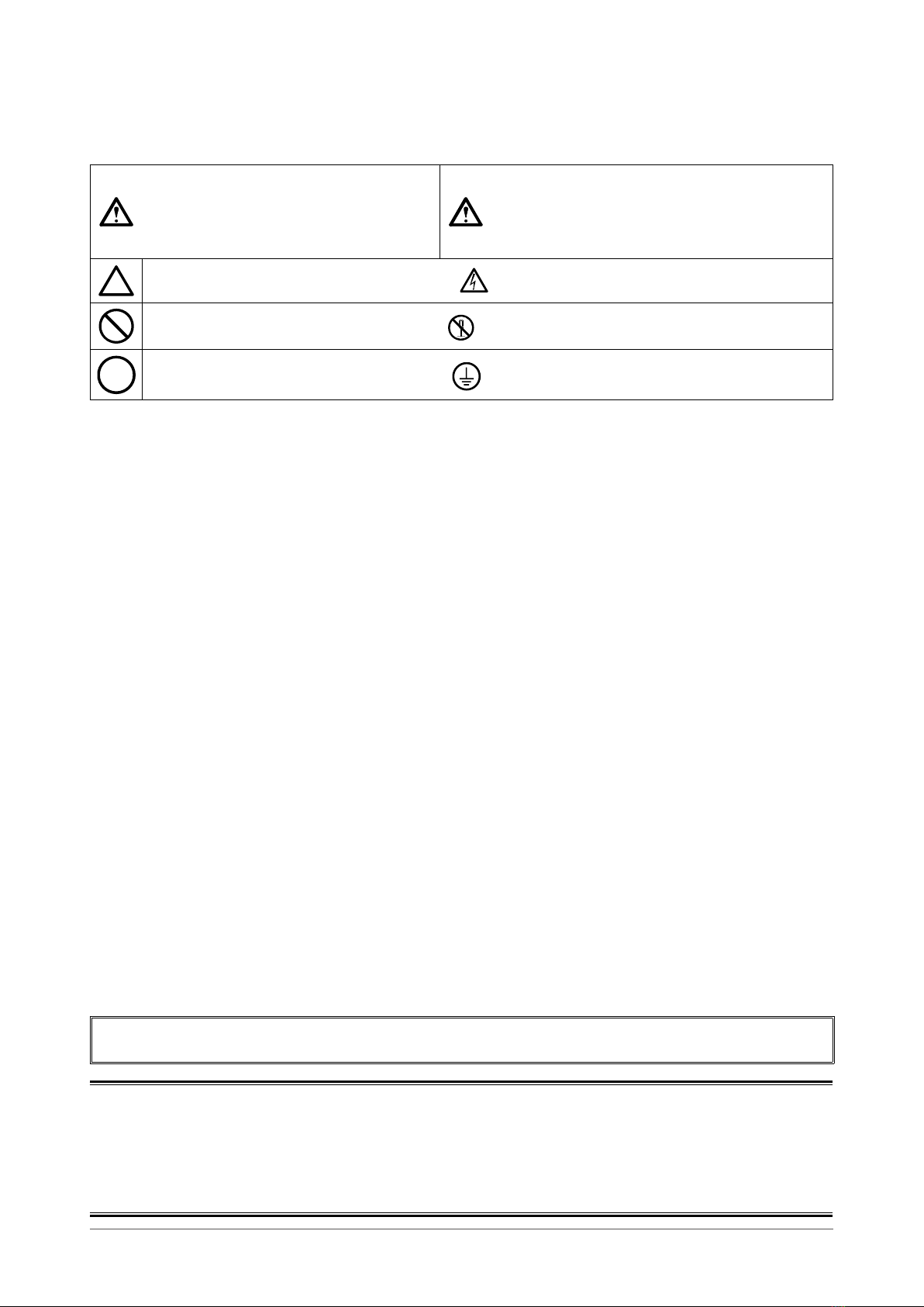
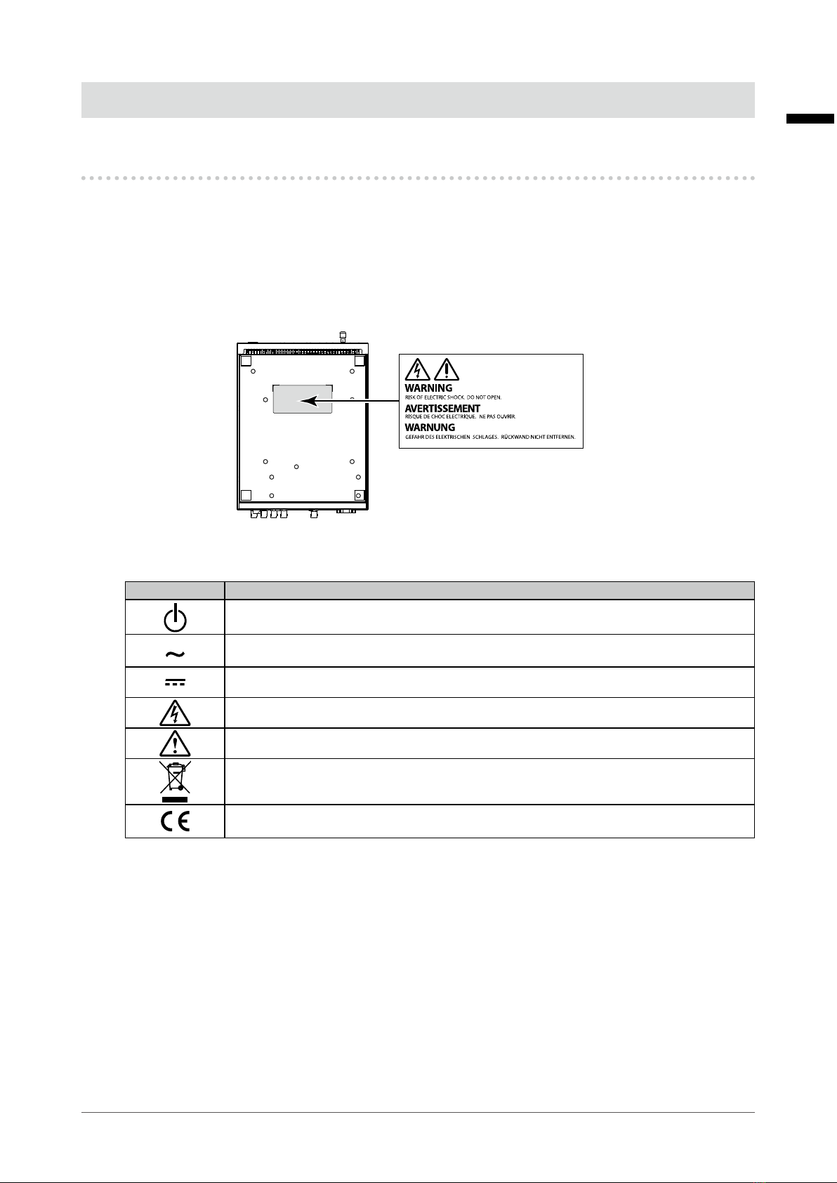
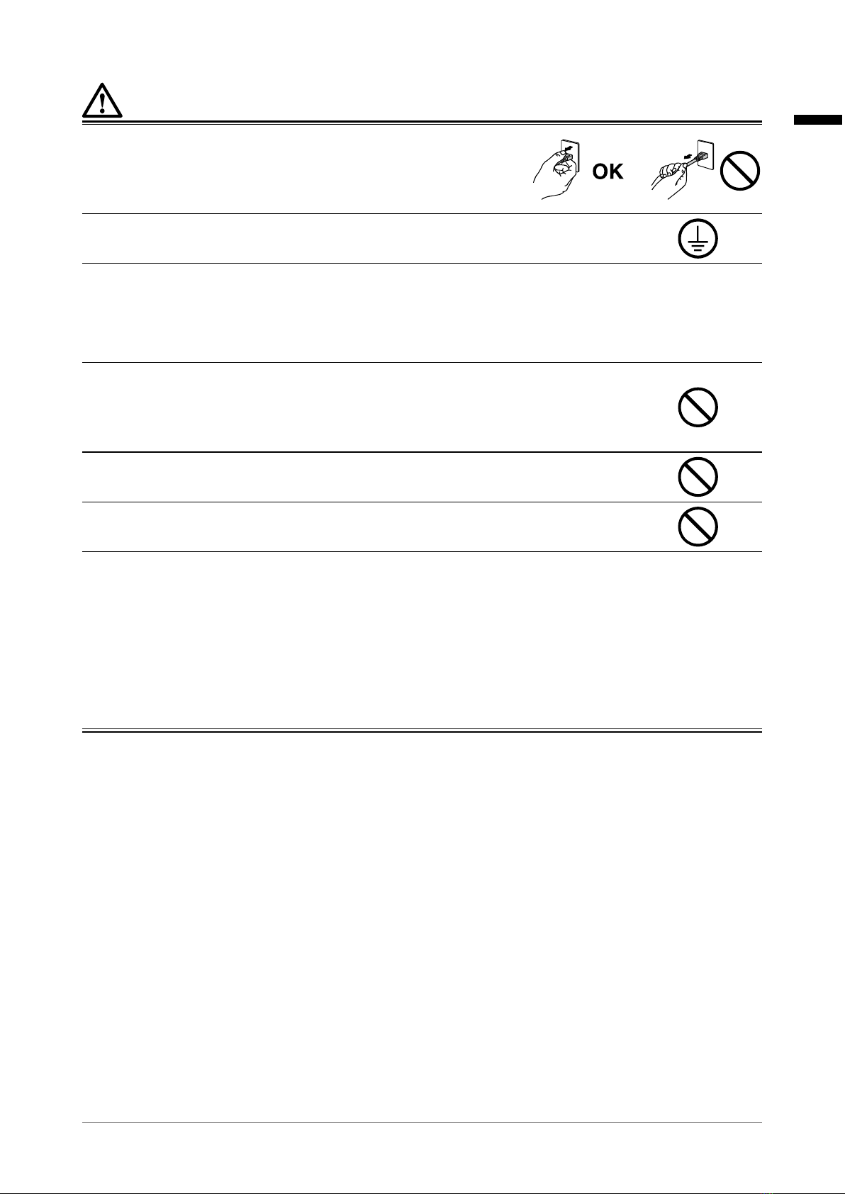
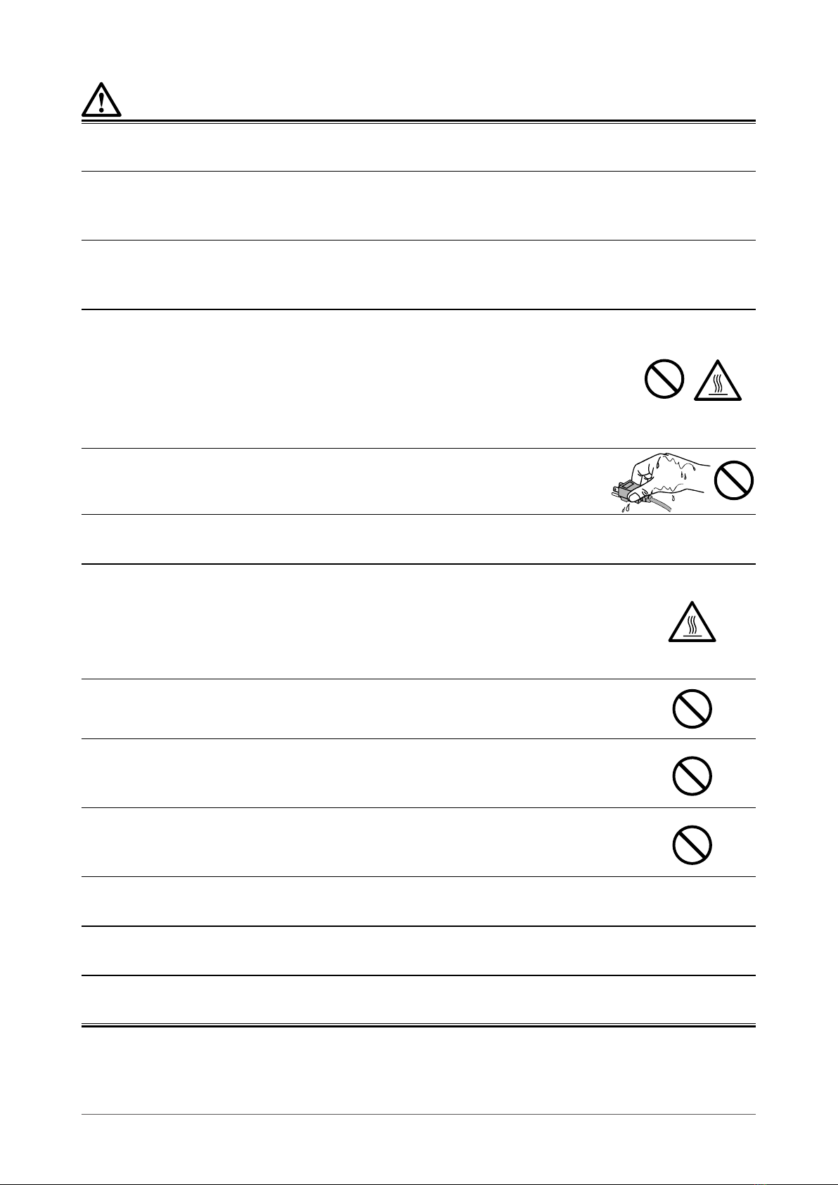
PRECAUTIONS ...................................................... 3
IMPORTANT .............................................................. 3
About This Product ............................................... 7
Intended Use ............................................................. 7
Precautions for Use ................................................. 7
Cautions for Network Use ....................................... 7
Cleaning .................................................................... 8
CONTENTS ............................................................. 9
Chapter 1 Introduction ..................................... 10
1-1. Features ........................................................10
●Camera Performance .....................................10
●Structure (Camera Mount) .............................10
●Installation ......................................................10
●Operation .......................................................10
●Output Interface .............................................10
●Other Functions ..............................................10
1-2. Package Contents ........................................11
1-3. Controls and Functions ..............................11
●AC Adapter .....................................................11
●CCU ................................................................12
●Camera ...........................................................14
Chapter 2 Setup ................................................ 16
2-1. Before Installing the CCU ...........................16
●InstallationRequirements ..............................16
●Attaching the Rubber Feet (Optional) ............16
2-2. Preparing the Camera .................................17
●Attaching a Filter or a Close-up Lens
(Optional) ........................................................17
●
Attaching the Camera to a Fixture (Arm/Stand)
...19
2-3. Connected .................................................... 20
●Connection Example ..................................... 20
●Connecting the Camera with CCU ................ 20
●Connecting Monitors and Encoders ..............21
●Connecting a Computer (Optional) ................21
●Connecting the Power Cord .......................... 22
2-4. Adjustments ................................................ 24
●Setting the Installation Direction ....................24
●Adjusting the Brightness ............................... 25
Chapter 3 Operation ......................................... 27
3-1. Camera Control ........................................... 27
3-2. Menu Operation ........................................... 28
Chapter 4 Setting .............................................. 29
4-1. ALC ............................................................... 29
4-2. Picture .......................................................... 30
4-3. Color ..............................................................31
4-4. Camera & Lens ............................................ 32
4-5. Video Output ............................................... 33
4-6. Audio ............................................................ 33
4-7. Device Setting ............................................. 34
4-8. Save/Load .................................................... 36
4-9. Information .................................................. 36
4-10. Language ......................................................37
Chapter 5 Maintenance .................................... 38
5-1. ExportingtheSettings ............................... 38
5-2. Loading the Settings .................................. 40
5-3. Software Update ......................................... 40
Chapter 6 Menu List ......................................... 41
Chapter 7 Troubleshooting .............................. 43
7-1. If No Image Is Displayed ............................ 43
7-2. Other Problems ........................................... 43
7-3. SpecicationsoftheLEDLighting ........... 44
●CCU Front ..................................................... 44
●Camera Front ................................................ 45
Chapter8 Specications ................................. 46
8-1. Specications ............................................. 46
8-2. ExternalDimensions ...................................47
●CCU ................................................................47
●Camera ...........................................................47
Appendix .............................................................. 48
Trademark ............................................................... 48
License .................................................................... 48
Medical Standard ................................................... 48
EMC Information .................................................... 49
Warning for Radio interference ............................ 53
LIMITED WARRANTY ............................................. 54
Recycling Information ........................................... 55

10 Chapter 1 Introduction
Chapter 1 Introduction
1-1. Features
●Camera Performance
• 4K resolution 60P
4K images can be captured in 60 frames per second
• Optical 30x zoom
●Structure (Camera Mount)
• Intelligent PTR (PAN/TILT/ROLL)
Integrated camera mount allows for simple control Improved movability
●Installation
• The camera can be installed sideways or upside down.
• To supply power and transmit video signals, all you need is a single cable to connect the Camera
Control Unit (CCU) with the camera. Easy to install and transport.
●Operation
• Operation on the CCU Control Panel
• IR remote controller included
• Communication Control (RS-232C/LAN)
●Output Interface
• 4K-supported
- HDMI(YUV420)
- QuadLink3G-SDI(SquareDivision(SQD)Signalor2-SampleInterleaveDivision(2SI)Signal,
YUV422, Level B not supported)
• FHD-supported
- HDMI(YUV422)
- 3G-SDI Level A (Level B not supported)
• Analog audio output
●Other Functions
• BT.2020EmulationMode(4KUHDSDI)
• Auto level control
• Noise Reduction
• ImagescanbeippedhorizontallyandverticallyCeiling-suspendedinstallationsupported
• Microphone included

English
11
Chapter 1 Introduction
1-2. Package Contents
Check that all of the following items are included in the package.
Note
• It is recommended that the box and packing materials be stored so that they can be used to move or transport the
product.
• CCU • IR remote controller (batteries included)
• Camera*1 • Rubber feet x 4
• Cover*2 • NDlter
• Close-up lens • Instructions for Use
• AC Adapter • Quick Reference Guide
• Power cord • Thread-lockinguid
• Camera cable
Attention
• Remove the batteries from the remote controller if it will not be used for a long time.
*1 A protection cover is attached to the lens at the shipment from the factory. Remove the cover before use.
*2 Cover for the rear side of the camera.
1-3. Controls and Functions
●AC Adapter
2 31
1. Main power indicator Depending on the operation status of the main power supply, the indicator of the
AC adapter turns on or off.
Lit up: Power on, Not lit up: Power off
2. AC IN terminal Connects the power cord.
3. DC OUT terminal Connects to the DC IN terminal on the CCU.

12 Chapter 1 Introduction
●CCU
Front
3
1
2
4
5
1. Power switch Turns the power on and off.
To turn the power off, press and hold the button for approx. one
second.
2. USB terminal*1 Connects a USB memory when updating the software.
See “5-3. Software Update” (page 40) for details.
3. IR sensor (light receiving section
of the remote controller)
It is the light receiving section of the remote controller. Do not block
the light receiving section.
4. LED Each LED indicator lights up according to the status of this product.
CAMERA The camera is ready to use.
LOCK The camera operation is locked.
MAINTENANCE A USB memory is connected.
See “Chapter 7 Troubleshooting” (page 43) for details.
5. Control Panel Used for controlling the camera and performing menu actions.
See “3-1. Camera Control” (page 27) for details.
*1 Remove the cover before use.

English
13
Chapter 1 Introduction
Rear
2 3 41
6
5
7 8 9 10
1. Camera connection terminal Connects the camera to the CCU with the provided cable.
2. HDMI output terminal (FHD)
*1
ConnectsamonitorequippedwithHDMIinput.FullHDimagesandaudio
are output.* 3
3. SDI output terminal (FHD) *1 ConnectsamonitorequippedwithSDIinput.FullHDimagesandaudio
are output.* 3, *4
4. HDMI output terminal (4K
UHD) *1
ConnectsamonitorequippedwithHDMIinput.4KUHDimagesand
audio are output.* 3
5. SDI output terminal (4K UHD)
*2
ConnectsamonitorequippedwithSDIinput.4KUHDimagesandaudio
are output.* 3, *5
6. RS-232C terminal Connects a computer to the CCU with a RS-232C cable (D-Sub 9 pin).
7. MODE switch DIP switches used for switching the settings are located.
No. ON/OFF Description
1 ON Set the switch to OFF.
OFF
2 ON Set the switch to OFF.
OFF
3 ON Set the switch to OFF.
OFF
4 ON PAL(50Hz)mode
OFF NTSC(60Hz)mode
* If the settings are changed, be sure to cycle the power supply.
The power is turned off for all the components in the factory
default state.
8. Ethernet connection terminal Connects a LAN cable here.* 6
9. Audio output terminal Connects an audio device. Analog audio is output.
10. DC IN terminal Connects the DC OUT terminal of the AC adapter.
*1 ImageandaudiosignalsaresimultaneouslyoutputfromrespectiveHDMIandSDIterminals(4types
total)forFullHDand4KUHDimages.
*2 Audio is output from Channel 1.
*3 Audio output is disabled in the default settings. Use “Audio” on the menu screen and enable audio output
from each port.
*4 3G/HD-SDIsupported.
*5 Quad Link 3G-SDI supported.
*6 100BASE-TX supported. Use cables in CAT 5 or higher.

14 Chapter 1 Introduction
●Camera
Front
1
4 23
1. Lens unit Itisazoomlens.AnNDlter(includedinthepackage)canbe
attached here.
2. IR sensor (light receiving section
of the remote controller)
It is the light receiving section of the remote controller. Do not block
the light receiving section.
3. LED The LED indicator lights up according to the camera status.
Flashing in green Initializing
Lit in green The camera is running.
Lit in orange PAN/TILT/ROLL is running.
Green and orange
lightsareashing
alternately
PAN/TILT/ROLL is restored to the origin.
See “Chapter 7 Troubleshooting” (page 43) for details.
4. Microphone It is a microphone used for recoding voice.

English
15
Chapter 1 Introduction
Rear
P/N
0FTD0000 ###
Mfd./ :yyyy-mm-dd
S/N/ 20000000 ## ##
05B29402A1
1 32 4
1. CCU connection terminal Connects the camera to the CCU with the provided cable.
2. MODE switch DIP switches used for switching the settings are located. The power
is turned off for all the components in the factory default state. Keep
this switch turned OFF.
3. USB terminal Used for maintenance
4. 3.5 mm mini-jack Used for maintenance

16 Chapter 2 Setup
Chapter 2 Setup
2-1. Before Installing the CCU
●Installation Requirements
• The product must be installed at a stable place that is strong enough to withstand the weight.
• The product must be installed at an appropriate location. Be sure to turn the power off and observe
the safety precautions when installing.
• Do not place the product in areas described below.
- Hotorcoldareas
The temperature range in the operating environment is from 0°C to 40°C/ 0°C to 35°C for
Camera.
- Highlyhumidareas
Thehumidityrangeintheoperatingenvironmentisfrom20to85R.H.(nocondensation)
- Neartheequipmentemittingstrongmagneticwavessuchastransformersandmotors
- Neartheequipmentemittingradiowavessuchaswalkie-talkiesandmobilephones
- Near a radio or TV station emitting strong radio waves
- Areasaffectedbythelightreectedfromawindoworauorescentlamp
- Underunstablelighting(whereickeringoccurs)
- Near laser light
- Near high-voltage cables or rail tracks
- Dusty or sandy areas
- Oscillating areas
- Areas where water droplets are likely to be formed
- Steamy or oily areas
- Specialenvironmentssuchasaammableatmosphere
- Areas where radiation, X-ray, chloride pollution, or corrosive gas is present
- Areas including pools and hot springs where chemical agent is used
• Install it horizontally. Do not install it vertically.
●Attaching the Rubber Feet (Optional)
1. When installing the CCU directly on a cart, attach the provided rubber feet (4
pcs) on the bottom.

English
17
Chapter 2 Setup
2-2. Preparing the Camera
●Attaching a Filter or a Close-up Lens (Optional)
SC430-PTRcomeswithanNDlterandaclose-uplens.
UsingtheNDlterisrecommended.
• NDlter
Thelterreducesthelightvolumeto1/4(twostagesdown).
It is effective under a surgical light or when your operating environment is too bright.
• Close-up lens
The minimum object distance for the camera is 1.5 m. By attaching the close-up lens, the minimum object
distance becomes 1.0 m.
If the focal length is shorter than 1.5 m, attaching the close-up lens is recommended.
Attention
• With the close-up lens attached, it is not possible to set the focal point farther than 2m.
Attention
• WhenusingtheNDlterand/ortheclose-uplens,usetheprovidedthread-lockinguidinordertoavoidthem
becoming loose or falling off.
Notethatoncetheyaresecuredinplace,itwillbedifculttoremovethem.Besuretocheckyouroperating
environment before attaching them.
• ToattachboththeNDlterandtheclose-uplens,attachtheclose-uplensrst.
ND filter
Close-up lens Camera
• Once the setup is complete, make sure that the light volume is appropriate by viewing actual images.

18 Chapter 2 Setup
1. Applyadropoftheprovidedthread-lockinguidatapproximatelythree
locationsonthelterattachingarea.
Attention
• Usetheprovidedthread-lockinguid.
• Thethread-lockinguidisnotanadhesiveagent.ForciblyrotatingtheNDltertoleftmaycausethelterto
be detached.
Thread-locking fluid
2.
RotatetheNDltertorightandtightenitsecurely.

English
19
Chapter 2 Setup
●AttachingtheCameratoaFixture(Arm/Stand)
The camera should be installed using an arm or stand.
Attention
• When installing, do so by carefully following the information in the User Manual about the arm or stand.
• Checkthatthexturemeetsthefollowingstandards.
- Clearance between the screw holes: 100 mm x 100 mm
- Max. weight allowed: Strong enough to support the total weight including the camera and accessories such
as cables
- Thescrewlengthmustmeetthefollowingspecication.
Camera's screw hole
Up to 30 mm deep
Fixture
Commercially available screw
• Pleasefollowthespecicationsforthescrewtighteningtorque.
If the tightening is not performed correctly, the attached part may be damaged, which may result in injury or
equipmentdamage.
Screwtighteningtorque 1.0 N·m to 1.4 N·m
Requiredtools Phillips screwdriver (No. 2)
• Connect the cables after attaching an arm or stand.
• Thecamera,arm,andstandareheavy.Droppingthemmayresultininjuryorequipmentdamage.
• Periodicallycheckthetightnessofthescrews.Ifnotsufcientlytight,themonitormaydetachfromthearm,
whichmayresultininjuryorequipmentdamage.
1. Fasten the attachment screws at the four screw holes on the bottom of the
cameratosecuretheattachmentxtureinplace.
Attention
• Pleasefollowthespecicationsforthescrewtighteningtorque.
Screwtighteningtorque 1.0 N·m to 1.4 N·m
Requiredtools Phillips screwdriver (No. 2)
Bottom of the Camera
Unit: mm
4 x M4 (MAX depth 30 mm)
100
25
100 9

20 Chapter 2 Setup
2-3. Connected
Attention
• Do not move the drive unit of the camera with your hand. Be sure to use the CCU Control Panel or the remote
controller.
●ConnectionExample
Camera cable
Camera Monitor, etc.
HDMIcable,etc.
Power cord
CCU
●Connecting the Camera with CCU
1. Connect the camera and CCU using a provided camera cable.
Attention
• Use the provided camera cable.
• In case of any damage is found with the cable, do not use it.
• Disconnect the power cord.
• During the work, be sure to observe the following:
- Do not touch the connector pins.
- Do not touch pins at the end of any cable connected to a connector.
- Take anti-static precautions such as using an anti-static wrist wrap when working.
Camera
Camera cable
CCU
2.
Attach the cover to the rear side of the camera.
Table of contents
Other Eizo Medical Equipment manuals