Ekinex EK-AM1-TP User manual

1
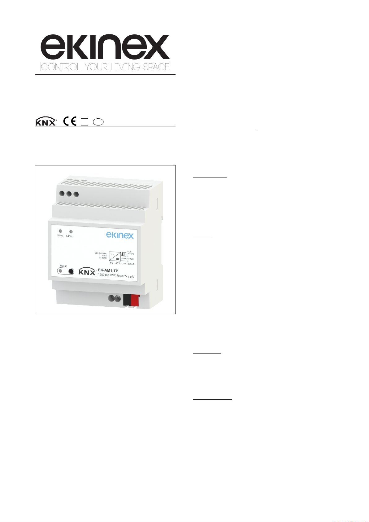
KNX bus power supply 1280 mA with 30
Vdc auxiliary output
Product code: EK-AM1-TP
• Cooling by free air convection
Main characteristics
• Housing in plastic material
• Mounting on 35 mm rail (according to EN 60715)
• Protection degree IP20 (installed device)
• Isolation class I
• Safety class II
• Overvoltage cathegory III (according to EN 61558, EN
50178, altitude up to 2000 m. s.l.m.)
• 4 modular units (1 UM = 18 mm)
• Dimensions 72 x 90 x 70 mm (WxHxD)
• Weight: 296 g
Environmental conditions
• Operating temperature: - 30 ~ + 70°C
• Storage temperature: - 40 ~ + 85°C
• Working humidity: 20 ~ 95% RH not condensing
• Storage humidity: 10 ~ 95% RH not condensing
Technical data
Power supply
• Mains voltage range 180 ~ 264 Vac, 176 ~ 280 Vdc
• Frequency range 47 ~ 63 Hz
• Power consumption 38.4 W
• Input AC current (typical) 0.5 A @ 230 Vac
• Inrush current (typical): cold start 60 A (twidth=1200 µs
measured at 50% lpeak) @ 230 Vac
• Leakage current: < 1 mA @ 240 Vac
Outputs
• Bus line voltage: 30 Vdc SELV
• Auxiliary voltage: 30 Vdc SELV
• Rated current (total outputs): 1280 mA
• Short circuit current: 2.8 A
• Setup, rise time: 1000 ms, 50 ms @ 230 Vac at full load
• Ripple & noise (max): 100 mVp-p (*)
• AC mains failure back-up time (typical): 200 ms @ 230
Vac at full load
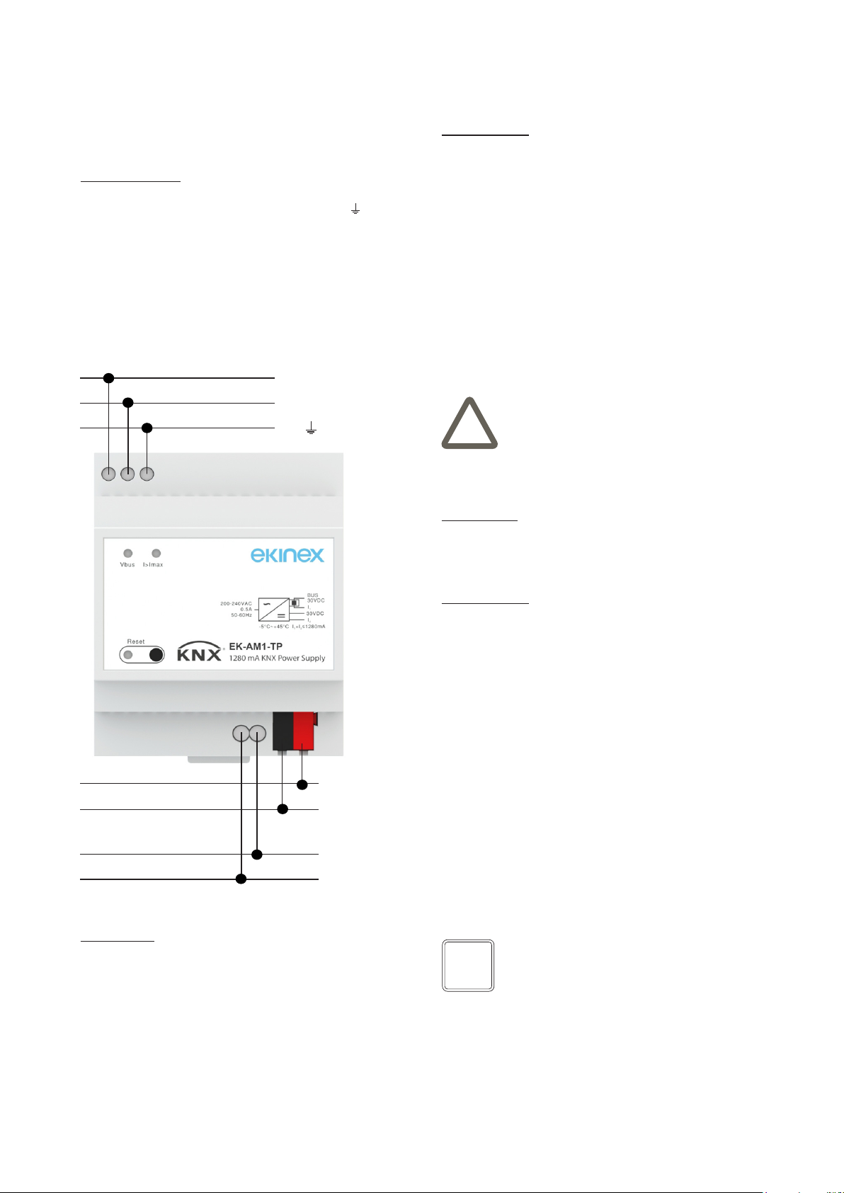
• Bus line connection: KNX terminal block (black/red) in-
cluded in delivery
• Auxiliary output connection: dedicated screw terminal
block
KNX device with function of power supply for a bus line
with auxiliary output. It has to be used in KNX installations
for control of homes and buildings.
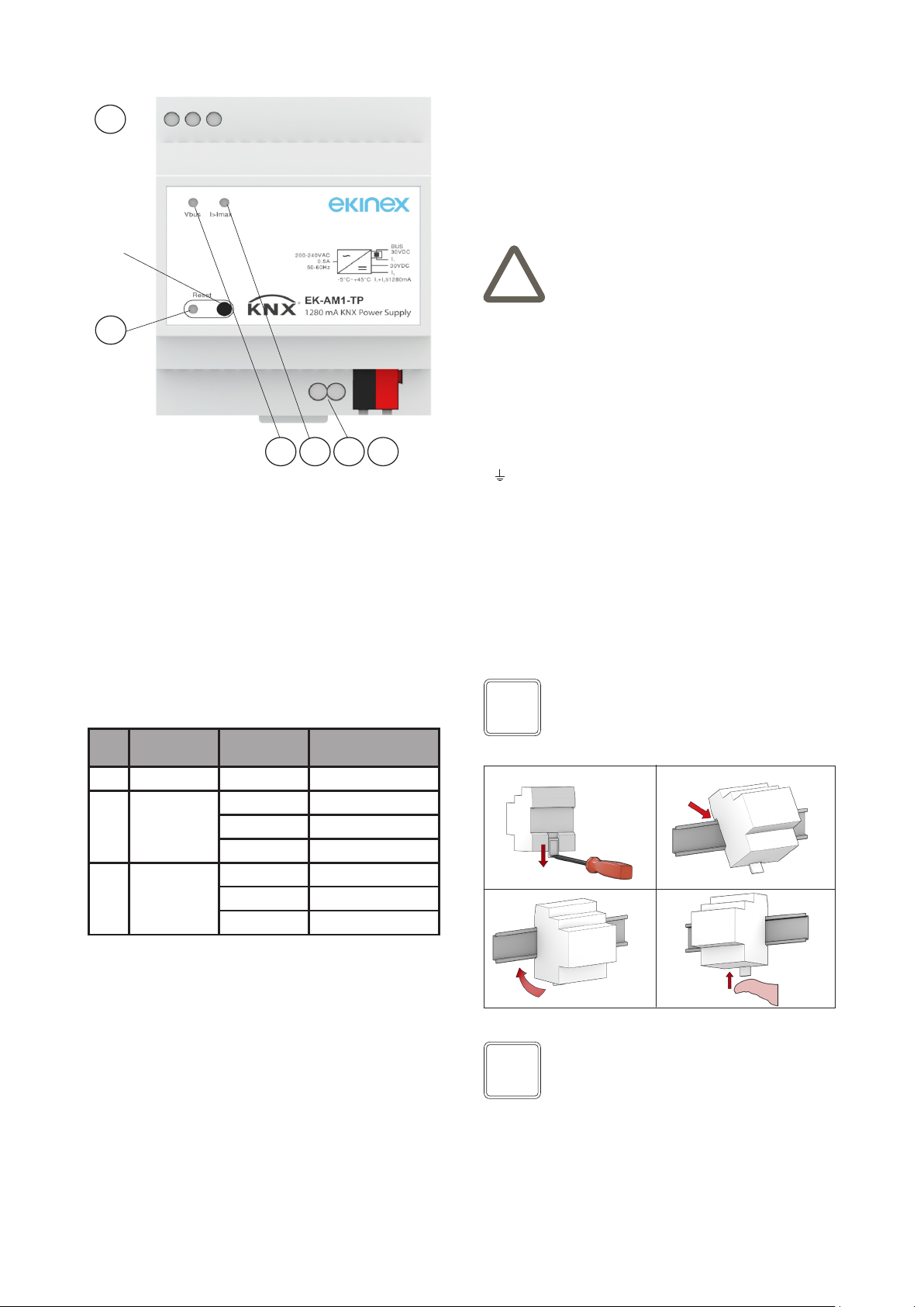
Description
The ekinex®power supply EK-AM1-TP is a KNX device
for rail mounting which produces and monitors the 30 Vdc
voltage required to operate the bus system. It has a 30
Vdc additional output, which can be used as a SELV (sa-
fety extra low voltage) auxiliary power for bus devices.
The device has an integrated choke which provides the
decoupling between the power supply and the information
on the bus line. On a KNX bus line can be connected up
to 256 KNX bus devices. The output is protected from
overload, short circuit and overvoltage. The total current
absorbed by the two outputs (KNX bus and auxiliary) can-
not exceed 1280 mA. The device can support short inter-
ruptions of the mains voltage (max 200 ms at full load).
Functions
• 30 Vdc SELV power supply for a KNX bus line with max
256 connected devices (depending on the current con-
sumption of each device)
• Auxiliary power supply 30 Vdc
• Reset of the connected bus line with a dedicated pu-
shbutton
• LED indicators for normal operation, bus reset and bus
overload
• Protections: overload, short circuit, overvoltage
Datasheet STEKAM1TP_EN
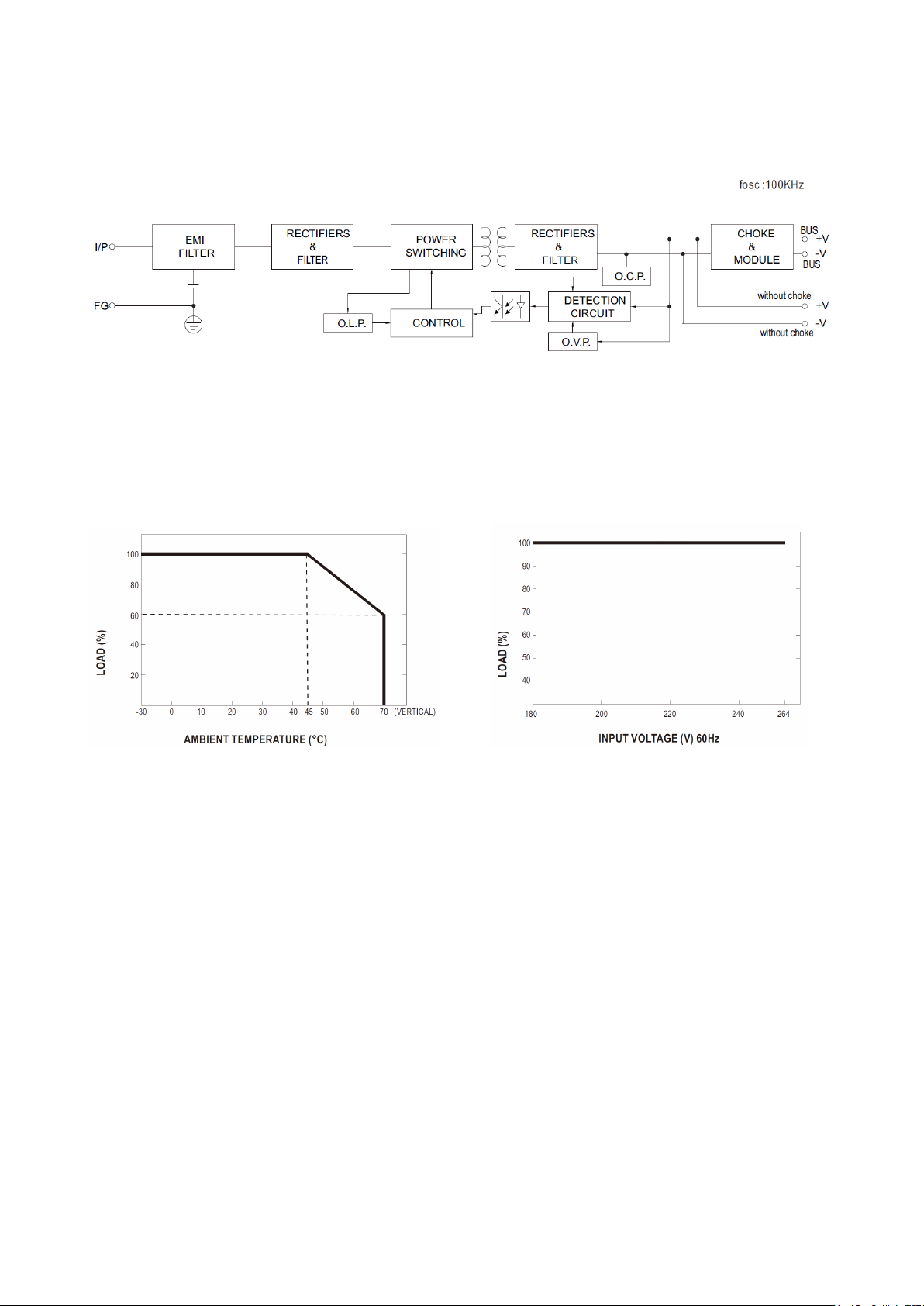
Protections
• Overload: 205 ~ 235% rated output power. Protection
type: constant current limiting, recovers automatically
after fault condition is removed
• Overvoltage: 33 ~ 35 V. Protection type : Hiccup mode,
recovers automatically after fault condition is removed
Safety and EMC
• Safety standards: EN 61558-1, EN 61558-2-16; EN
50491-3
• Withstand voltage I/P-O/P: 4, 2KVAC I/P-FG: 2KVAC
• Isolation resistance: I/P-O/P, I/P-FG: 100 MΩ @ 500 Vdc
@ 25 °C @ 70% RH
• EMC emission: compliance to BS EN 50491-5-2, -5-3;
BS EN 61000-3-2, -3-3
• EMC immunity: compliance to BS EN 50491-5-2, -5-3;
BS EN 61000-4-2, 3, 4, 5, 6, 8, 11.
TP
S
REAEKAM1TP
(*) Note: Ripple & noise are measured al 20 MHz of bandwidth
by using a 12’’ twisted pair-wire terminated with a 0,1 μF and 47
μF parallel capacitor. The measure is done before the decoupling
choke.

2
Mounting
The device has degree of protection IP20, and is the-
refore suitable for use in dry interior rooms. The hou-
sing is made for rail mounting according to EN 60715
in boards or cabinets for electrical distribution. The
installation is in horizontal position, the correct posi-
tion is when the terminals for KNX bus line and auxi-
liary output are located at the bottom and the terminals
( , L, N) for connecting the input mains power supply
Vac, Vdc are located at the top. For the installation of the
device on the rail proceed as follows:
For the installation of the device on the rail proceed as
follows:
• with the aid of a tool bring the locking device in the
fully lowered position (a);
• place the upper edge of the rear inner prole on the
upper edge of the rail (b);
• rotate the device towards the rail (c);
• push the locking device upward until it stops (d).
At the same bus line can be connected not more than two
power supplies. A second power supply may be necessa-
ry when the installation in distribution boards requires a
particular concentration of the bus devices (tipically more
than 30 units installed within 10 m). In this case a po-
wer supply has to be installed near the group of devices.
Between two power supplies installed on the same bus
line a minimum distance of 200 m is required, measured
along the line.
Planning
Planning a KNX bus installation, the use of a 1280 mA po-
wer supply unit requires to take into account the following
guidelines:
• the maximum number of bus devices connected is
256;
• the maximum length of a line segment is 350 m, me-
asured along the line between the power supply and
the furthest bus device;
• the maximum distance between two bus devices can-
not exceed 700 m;
• the maximum length of a bus line is 1000 m, keeping
into account all segments.
Switching, display and connection elements
The device is equipped with a reset pushbutton, 3 LEDs
and terminal blocks for mains voltage 180 ~ 264 Vac (or
176 ~ 280 Vdc), KNX bus line and auxiliary output.
The LEDs behaviour is as follows:
a b
dc
EKINSTGUIDAEKAM1TP
Warning! In order to supply the KNX bus lines use
only KNX bus power suppliers. The use of dierent
power suppliy units can compromise the communi-
cation and damage the devices connected to the
bus.
!
Note. When mounting the device in boards and ca-
binets it shall be provided the necessary ventilation
so that the temperature can be kept within the ope-
rating range of the device.
i
1) Terminal blocks for input power supply 180 ~ 264 Vac, 176 ~ 280 Vdc
2) Reset pushbutton
3) Reset LED (red)
4) Terminal block for KNX bus line
5) Terminal block for auxiliary 30 Vdc output
6) KNX output voltage LED (green/orange/red)
7) Output current LED (green/orange/red)
3
2
1
5 467
LED Type LED colour /
display
Meaning
3 KNX reset Red / solid KNX bus restart
6 KNX output
voltage, Vbus
Green / solid 28 < Vbus < 31 Vdc
Orange / solid Vbus < 28 Vdc
Red / solid Vbus > 31 Vdc
7 Output cur-
rent, I > Imax
Green / solid I < 1280 mA
Orange / solid I = 1280mA ~ 1600mA
Red / solid I > 1600mA (overload)
Note. It is recommended that the installation of the
device always ensure the full accessibility of the
front side to allow the operation of the pushbuttons.
i

3
KNX bus line
The connection to the KNX bus line is made with the ter-
minal block (black/red) included in delivery and inserted
into the slot located on the left bottom part of the front.
Characteristics of the KNX terminal block:
• spring clamping of conductors
• 4 seats for conductors for each polarity
• terminal suitable for KNX bus cable with single-wire
conductors and diameter between 0.6 and 0.8 mm (20
~ 22AWG)
• recommended wire stripping approx. 5 mm
• color codication: red = + (positive) bus conductor,
black = - (negative) bus conductor
Auxiliary output
The 30 Vdc auxiliary output has a dedicated connection
screw terminal block.
Characteristics of the terminal block for the auxiliary ou-
tput:
• screw clamping of conductors
• conductor wiring size: solid 0.5 ~ 4.0 mm2 or stranded
0.5 ~ 2.5 mm2 (12 ~ 26AWG)
• recommended wire stripping approx. 6 mm
• torque max 0.8 Nm
For the connection of the auxiliary output and the powe-
red devices it is recommended to use a cable with a she-
ath of a dierent color than the cable connecting the KNX
bus line.
Warning! The electrical connection of the device
can be carried out only by qualied personnel. The
incorrect installation may result in electric shock or
re. Before making the electrical connections, make
sure the power supply has been turned o.
!
Note. The conguration and commissioning of KNX
devices require specialized skills. To acquire these
skills, you should attend the workshops at KNX cer-
tied training centers.
i
Before removing the device, be sure the inputs have been
disconnected and the bus terminal has been extracted
from its slot. Use a screwdriver to slide down the locking
device and remove the device from the rail.
Electrical connections
Input main supply
The connection to the input main supply 180 ~ 264 Vac,
176 ~ 280 Vdc is made with screw terminals ( , L, N)
located on the upper front of the device.
Characteristics of the terminal blocks:
• screw clamping of conductors (use a slotted screwdri-
ver 2.5*0.4-3.5*0.6)
• Conductor wiring size: 0.5 ~ 4.0 mm solid core or 0.5 ~
2.5mm nely stranded
• recommended wire stripping approx. 6 mm
• torque max 0.8 Nm
Conguration and commissioning
Conguration
The device does not require any conguration with ETS®
(Engineering Tool Software) tool. The application softwa-
res APEKAM1TP##.knxprod (## = version) is available in
order to add the power supply to an ETS project.
Commissioning
For the commissioning of the device turn on the input
mains power supply to which the device is connected.
The LED marked “Vbus” solid green indicates the device
operating in the normal range.
Reset
The device has a reset pushbutton. By keeping it pressed
for at least 20 seconds, the bus line is not powered for
20 seconds and the bus devices connected are restored
to their original condition. During this interval of time the
reset LED (red) is turned permanently on.
Failure
When the LED labeled “I > Imax”, is turned on solid oran-
ge or red, this means that the KNX output is overloaded or
short-circuited. The problem can be solved by removing
the cause of the short circuit or by reducing the number of
KNX devices connected to the line. After the removal of
the problem only the green LED “Vbus” is turned on, at this
time it is recommended to reset the line.
L
N
PE
+
-
V input
AUX
30Vdc
Bus
KNX
+
-

4
Disposal
At the end of its useful life the product
described in this datasheet is classied
as waste from electronic equipment in
accordance with the European Direc-
tive 2012/19/UE (WEEE recast), and
cannot be disposed together with the
municipal undierentiated solid waste.
Marks
• KNX
• CE: the device complies with the Low Voltage Directi-
ve (2014/35/EU) and the Electromagnetic Compatibility
Directive (2014/30/EU).
• Tests carried out according to BS EN 61558-
1:2005+A1:2009, BS EN 61558-2-16:2009+A1:2013,
BS EN 50491-5-2:2010, BS EN 50491-5-3:2010, BS
EN 61000-3-2:2014, BS EN 61000-3-3:2013, BS EN
61000-4-2, 3, 4, 5, 6, 8, 11
Maintenance
The device is maintenance-free. To clean use a dry cloth.
It must be avoided the use of solvents or other aggressive
substances.
Dimensions [mm]
Documentation
This datasheet refers to the release A1.0 of the ekinex®
device EK-AM1-TP and it is available for download at
www.ekinex.com as a PDF (Portable Data Format) le.
Warnings
• Installation, electrical connection, conguration and
commissioning of the device can only be carried out
by qualied personnel in compliance with the appli-
cable technical standards and laws of the respective
countries
• The use of the device in security applications is not
allowed.The device may however be used for auxiliary
signaling functions
• Opening the housing of the device causes the imme-
diate end of the warranty period
• In case of tampering, the compliance with the essen-
tial requirements of the applicable directives, for which
the device has been certied, is no longer guaranteed
• ekinex®KNX defective devices must be returned to the
manufacturer at the following address: EKINEX S.p.A.
Via Novara 37 I-28010 Vaprio d’Agogna (NO) Italy
Other information
• This datasheet is aimed at installers, system integra-
tors and planners
• For further information on the product, please contact
the ekinex®technical support at the e-mail address:
com
• Each ekinex®device has a unique serial number on
the label. The serial number can be used by installers
or system integrators for documentation purposes and
Warning! Incorrect disposal of this product may
cause serious damage to the environment and hu-
man health. Please be informed about the correct
disposal procedures for waste collecting and pro-
cessing provided by local authorities.
!
File name Device release Updating
STEKAM1TP_EN.pdf 1.0 04 / 2022
-V +V

5
has to be added in each communication addressed to
the EKINEX technical support in case of malfunctio-
ning of the device
• KNX®and ETS®are registered trademarks of KNX
Association cvba, Brussels
© EKINEX S.p.A. The company reserves the right to make changes to this
documentation without notice.

6
Annex 1 - Powering KNX bus only
+
-
Bus
KNX
L
N
PE
V input
Lightning
device
HVAC
device
Blind / Shutter
actuator Other devices
I1
-V +V -V +V
Bus wiring consideration:
• the maximum number of bus devices connected is 256
for TP1-256 topology;
• the maximum length of a line segment is 350 m, mea-
sured along the line between the power supply and the
furthest device bus;
• the maximum distance between two bus devices can-
not exceed 700 m;
• the maximum length of a bus line is 1000 m, keeping
into account all segments;
• It is possible to connect two EK-AM1-TP in parallel with
the following conditions: two chokes installed in one
line with at least 200m apart.
Annex 2 - Powering KNX bus and KNX devices
+
-
Bus
KNX
L
N
PE
V input
I1
I2
-V +V
-V +V
• Use the auxiliary output of EK-AM1-TP only to power
the KNX device;
• The totaI current I1+I2should be equaI or less than 1280
mA;
• The above bus wiring consideration (Annex 1) is still
applicable.
Lightning
device
HVAC
device
Blind / Shutter
actuator Other devices

7
Annex 3 - Block diagram
Annex 4 - Characteristics
Derating curve Static characteristics
Table of contents
Other Ekinex Power Supply manuals
Popular Power Supply manuals by other brands

Pyle
Pyle PSL462X instruction manual

StarTech.com
StarTech.com ATXPOW300SL Instruction guide

Omron
Omron E39-VA instruction sheet

Elektro-Automatik
Elektro-Automatik EL 9000 HP Series instruction manual

CARLO GAVAZZI
CARLO GAVAZZI XAP10RSEXX Configuration manual

EFLOW
EFLOW eFlow 104N Series installation guide

ELC
ELC AL 912AE instruction manual

IFM
IFM AC1253 installation manual

ARBOR SCIENTIFIC
ARBOR SCIENTIFIC Spectrum Tube Carousel System Instructional guide

Broncolor
Broncolor SENSO A2 operating instructions

Avansa
Avansa PREMIUM 300W/500VA-12VDC user manual

Keysight Technologies
Keysight Technologies E36150 Series Service guide