Guidance Notes:
The total load must not exceed the rating of the incoming device or the assigned assembly rating (InA) whichever is the lower. Each neutral and earth
connection must correspond numerically to its outgoing way. Additional blanks (ref. JK01B) are available to cover spare ways.
A pack is provided to label this consumer unit, please consult us for spares or replacements.
Operating Instruction leaet is provided overleaf. This leaet should be left for the end user.
Single conductors below 1.5mm² need to be doubled back in the terminal bar.
Consumer Units incorporating RCDs in TT systems should incorporate an S type (time Delayed) RCCB, e.g. 100 mA s-type RCCB . Alternatively a main
switch with RCBO protection on all outgoing circuits should be used.
Precautions need to be taken to prevent faults to earth on the supply side of the RCD (as per BS7671 regulation 531.4.1)
IP Ratings:
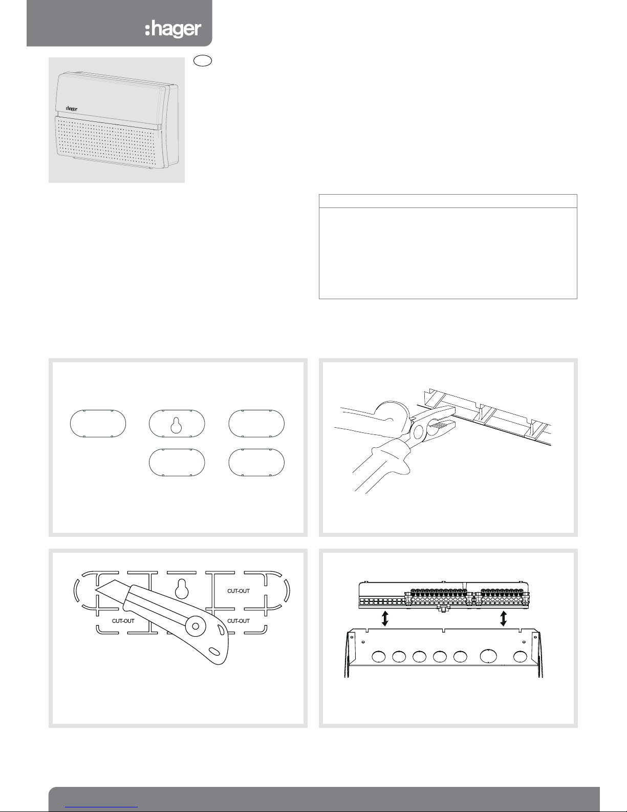
Cable access into the consumer unit must maintain the integrity so far as reasonably practicable. In essence, for surfaces accessible after installation,
this means maintaining the requirement for the horizontal top surface of the enclosure to provide a degree of protection of at least IP4X and elsewhere,
IP 2XC. For rear cable access, the minimum number of knockout(s) shall be removed.
Warranty
This distribution board is offered with a 24 month warranty against defective material or manufacture. If a warranty claim is necessary, please call the
technical support number given at the bottom of the page and we will be pleased to help.
For dimensional information and weights please consult the Hager catalogue.
Hager Technical Help Line: 01952 675 689
Hager Technical Fax: 01952 675 557
Website: www.hager.co.uk
E-mail us: info@hager.co.uk
Fitting Hager MCBs and RCBOs:
Only equipment and arrangements specied in Hager’s technical
documentation / catalogue shall be used.
Isolate the electrical supply from the consumer unit.
1. Isolate the electrical supply from the consumer unit.
2. Remove the front cover.
3. Fully slacken the lower terminal of the device.
4. Fully open the bottom device clip (g 1.)
5. Locate the device onto the din rail, and busbar. Ensure that the
busbar tooth is within the device terminal cage.
6. Close the bottom device clip.
7. While holding the device rmly onto the busbar, fully tighten the lower
terminal screw.
8. After tting all outgoing devices and connecting all outgoing cables,
please check the tightness of all cable connections. This should
include all factory made connections, which may have loosened
during installation or transit.
g 1.
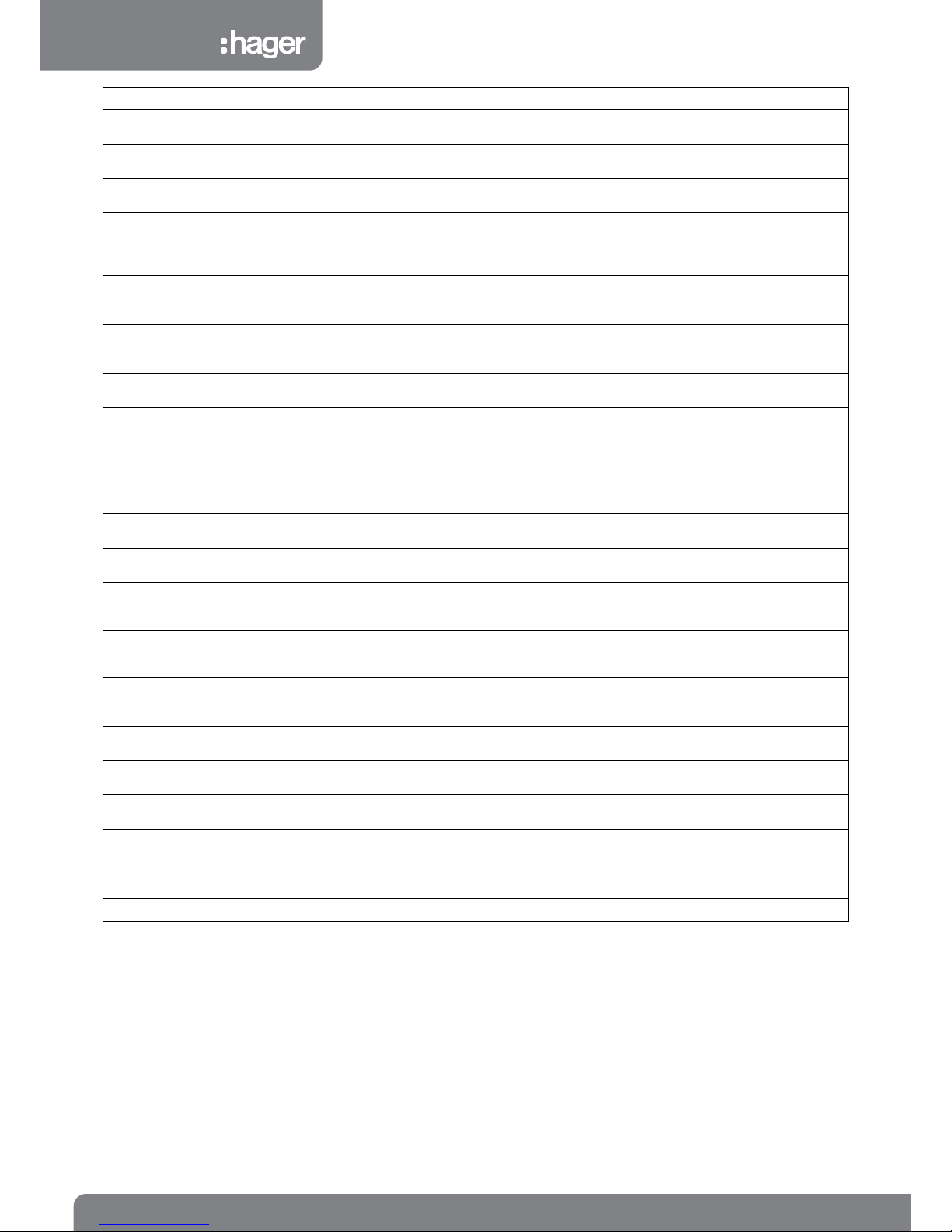
IP Code Description
IP2XC Protection against access
with a tool (2.5mm diameter,
100mm long) making contact
with live hazardous parts
IP4X A probe of 1mm diameter
shall not enter the enclosure
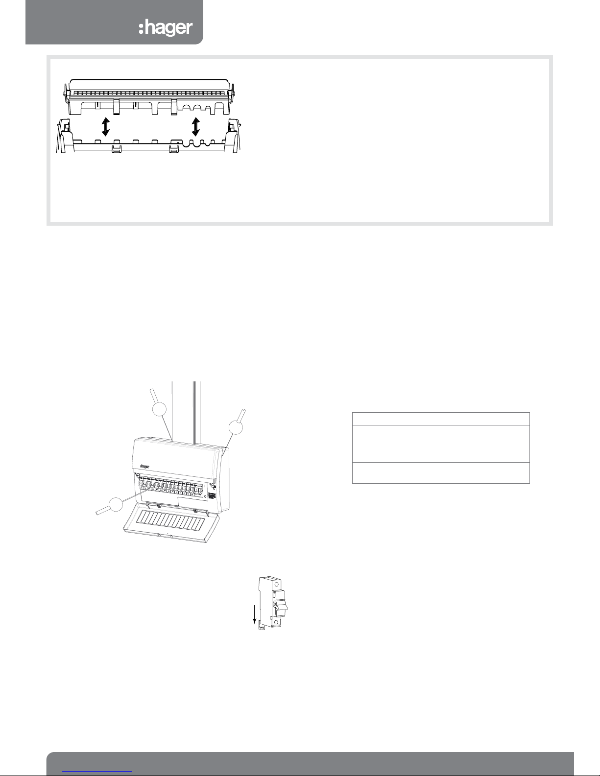
Insulated Unit - Removing and replacing the top wall for top surface cabling
(IP4X using foam inserts; 1mm2- 10mm2 conductors BS6004)
1. Press in with index nger on one end release clip while pressing in with thumb
on the inner release clip repeat on the other and lifting the wall away from the
unit.
2. After xing the unit, to replace and reseal, place one of the foam seal strips in
the underside of the wall feature and the other in the base (behind the cables).
Locate the wall and press down. Additional xing points are provided.
Max outgoing top entry cable size 10mm2CSA.
Max incoming Main tails top entry cable size 25mm2CSA.
If larger cables are needed, then enter from any other cable entry point other than
top.
2ZD0632 - Issue 5 03-15
ZD0632 ZD0632
IP2XC
IP2XC
IP4X