EKKO EP15LI User manual

1
SPECIFICATION
Lithium-ion Walkie Electric Pallet truck
EP15LI

2
Introduction
In order to meet the needs of the national environmental protection request, To reduce
industrial pollution and improve productivity, we develop new series of EP15LI walkie
Electric Pallet truck on the basis of absorption of the advantages of domestic & overseas
battery Pallet truck. They are especially suitable for cargo loading and unloading, handling,
stacking, etc for food, bank, light textile, station, port, logistics and other enterprises.
This manual describes the technical parameters of the Pallet truck, working principle and
operation, maintenance, and other aspects. It can help operators use the Pallet truck more
reasonable, make its maximum effect.
It is hoped that Operator strictly abide the regulations and the precautions in this manual
when using the Pallet truck. Carefully use them so that your Pallet truck can be in the best
working condition for long period of time to maximize its effectiveness. And create better
economic benefits.

3
The Statement
Our company production model EP15LI type 3300LBS Walkie Electric Pallet Truck is a
special motor vehicle used in factory ,tourist attractions ,amusement places which is
specified by “special equipment safety supervision regulations”.

4
Catalogue
1.The General Introduction ......................................................................................5
2.Proper usage............................................................................................................6
Modification...........................................................................................................6
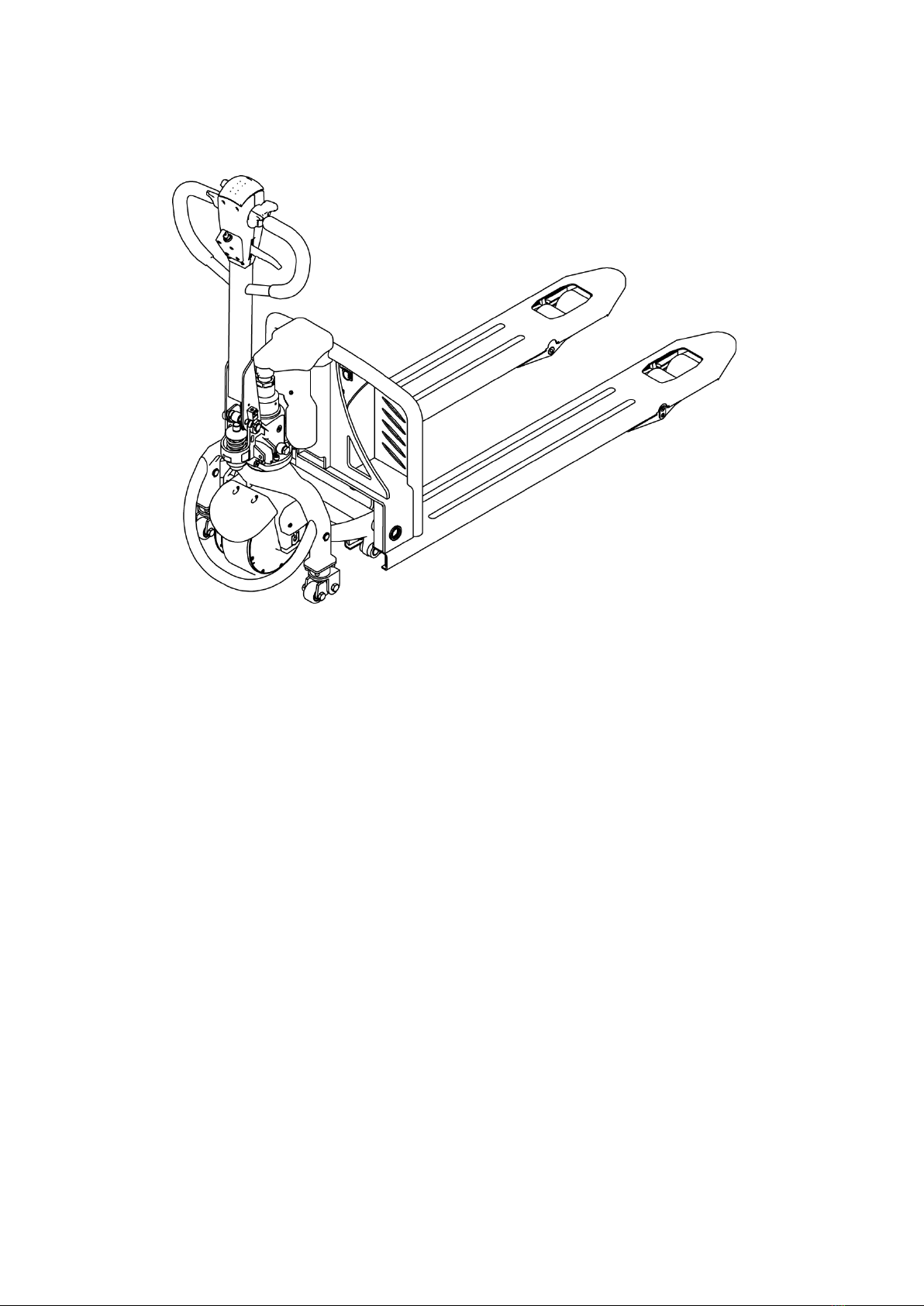
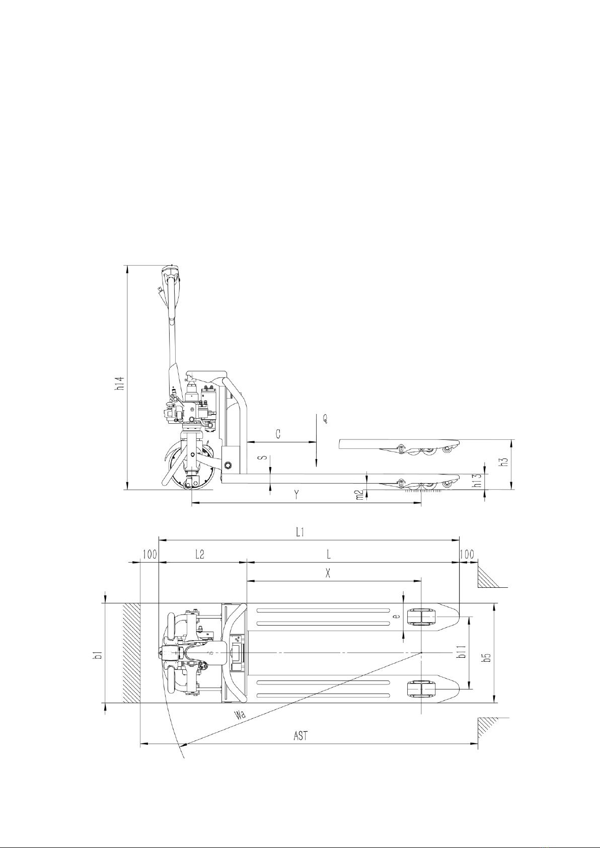
3.Introduction of the product......................................................................................7
3.1Model overview................................................................................................7
4.Operating principle ................................................................................................9
Operating mechanism diagram:...........................................................................9
5.Operating principle ..............................................................................................10
5.1Running system..............................................................................................10
5.2Steering system ..............................................................................................10
5.3 Brake structure and brake schematic diagram...........................................10
5.4 Operating System ..........................................................................................12
5.5 Electric System ..............................................................................................12
5.6 Hydraulic principle .......................................................................................12
6. Electrical schematic diagram ............................................................................13
6.1Electrical schematic diagram ........................................................................13
7. Hydraulic Scheme ................................................................................................14
7.1Hydraulic Scheme ..........................................................................................14
8.Operating Instruction ..........................................................................................15
8.1 Operation .......................................................................................................15
8.2Emergency reverse function .........................................................................17
8.3 The use of the horn and the reversing horn ...............................................17
8.4 Battery capacity display ...............................................................................17
8.5 operation........................................................................................................17
9.Safety operation and matters needing attention ...........................................18
9.1 Repair and Maintenance...............................................................................18
9.2 Routine Maintenance ....................................................................................19
9.3 Professional Maintenance Manual...............................................................19
9.4 battery maintenance, charging and maintenance. .....................................22
10.Safety Caution......................................................................................................26
10.1 General rule .................................................................................................26
10.2 Storage and transportation........................................................................26
10.3 Check before using......................................................................................27
10.4Safety operation regulation ........................................................................27
11.Service Manual....................................................................................................31
11.1 Troubleshooting.......................................................................................31
11.2 Preparation before repair ..........................................................................32
11.3Check the amount of hydraulic oil..............................................................32
11.4 Complete repair, the preparation before using........................................32
12.After Sales Service..............................................................................................33

5
1.The General Introduction
EP15LI is a Walkie type electric pallet truck. It adopts the advanced structure such as ring
rod lifting system and new AC controller, at same time it is equipped with high quality motor,
lithium battery and pump station motor. It has the characteristics of superior performance,
convenient operation, flexible steering, reliable braking, good dynamic performance, less
noise, less pollution and beautiful appearance.
This series truck is suitable for working on the smooth ground in warehouse, if not, please
don’t use it.
The service environment:
a. temperature not over +40℃,not under-10℃;
b. the gradient can’t over 3%;
c. when environment temperature at +40℃,the relative humidity can’t over 50%,At
low temperature,allow big relative humidity;
d. ground need hard and flat;
e. It is forbidden to use this car in corrosive environment such as flammable and
explosive or acid base.

6
2.Proper usage
Please using the electric pallet truck accord to this specification.
This is a tramp type electric pallet truck with autonomous control , lifting and lowering
is controlled by the handle button. Improper use can cause personal injury or machine
damage. Operators or operating companies need to ensure proper using,
The Truck needs to be used on a firm ,flat ,intact surface and suitable surface ,The truck
is designed for indoor use at room temperature from-10°C to +40°C
Use under light load without using permanent barriers or pits ,It is forbidden to operate
on the slopes .During Operation ,The goods must be placed approximately at the center of
the truck’s load center
Lifting or Carrying people is strictly prohibited ,If carried goods .The goods must fall on
the lifting point 。
It is prohibited to use this truck on lifting or loading ramps.
The rated capacity is marked on the capacity label or nameplate. And the operator must
pay attention to the warming signs and safety instructions.
Operating lighting must be at lest 50LUX
Modification
Any modification that may affect the truck rated capacity, stability, or safety operations must
be approved in advance by the Truck’s original manufacturer or Its authorized Manufacturer
or its successor. This includes the effects of changes such as Braking ,steering ,Visibility, and
the addition of removable accessories.
After the manufacturer or its successor approves the modification or change ,The capacity
name plate ,Label, identification marks, operation and maintenance manual must be changed
accordingly
Truck damage caused by not following Instruction will lose its warranty.

7
3.Introduction of the product
3.1Model overview
This specification is for EP15LI series3300LBS Walkie type electric pallet truck(follow as
truck).
The type is“EP15LI—15 load capacity is 3300LBS”
3.2Model parameters

8
Mode
EP15LI
Drive type
Electric
Manner of operation
Tramp type
Load Capacity
Q (LBS)
3300
Load Centre
c (Inch)
23.62
Distance between fork backrest and front
wheel
x (Inch)
37.17
Wheelbase
y (Inch)
48.94
Service Weight with battery)
LBS
352
Tire material
PU
Driving wheel size
Φ×w (Inch)
Φ9.84×2.91
Balance wheel size
Φ×w (Inch)
Φ3.15×2.36
Qty of wheel Front/Rear=driving wheel)
2/1x
Tread
b11 (Inch)
21.06
Lifting Height
h3 (Inch)
7.87
The height of handle in the operation position
h14 (Inch)
24/47.72
Lowered fork height
h13 (Inch)
3.35
Overall Length
l1 (Inch)
63.58
Body Length
l2 (Inch)
18.3
Overall Width
b1/ b2 (Inch)
26.97
Fork Size
s/e/l (Inch)
1.97/5.9/45.27
Fork Width
b5 (Inch)
26.97
Ground clearance under mast
m2 (Inch)
1.38
Aisle width for pallets 1000*1200 crossways
Ast (Inch)
71.46
Aisle width for pallets 1000*1200 lengthways
Ast (Inch)
73.42
Turing Radius
Wa (Inch)
55.23
Driving Speed, load/unload
(km/h)
4.2/4.5
Maximum gradeability load/unload
(%)
5/8
Brake Type
Electromagnetic brake
Drive Motor
(kW)
0.75

9
Lift Motor
(kW)
0.8
Battery,according to DIN 43531/35/36
A,B,C,no
no
Battery voltage/rate capacity
(V/Ah)
24v/35ah
Battery Weight(±5%)
(LBS)
15.4
Noise level
(dB(A))
≤70
Steering type
Manual steering system
4.Operating principle
The Truck with battery as power producer and controlled by electrical and hydraulic, trucks
can do some actions like walking, turning, pallet fork lift, etc.
Operating mechanism diagram:
1. Falling knob 2.Driving button 3.Lifting button
4.Emergency Reverse Button 5.Horn 6.Electricity meter

10
5.Operating principle
5.1Running system
The truck is powered by a battery, which is realized by controlling the AC motor on the drive
wheel. The speed of walking is realized by frequency conversion control motor speed, which
is controlled by the accelerator.
5.2Steering system
The steering of the moving car is driven by the handle lever through the handle lever to
drive the drive motor to realize the steering.
5.3 Brake structure and brake schematic diagram.
Braking performance depends on road conditions and vehicle load conditions.
5.3.1The brake function can be activated by the following ways:
⚫Turn the travel switch (2) to "0" position or release the switch to make truck brake until
it stops.
⚫With the driving switch (2) moving directly from one driving direction to the opposite
direction, the vehicle regenerates the brake until it begins to move in the opposite
direction.
⚫The handle moves up and down to the braking area (' B ') and the truck brakes.If the
handle is released, the handle automatically moves to the upper braking area (' B ') and
the truck stops until it stops.
⚫Emergency Reverse button (4) can prevent the operator will be squeezed, when trucks

11
are driven towards (' Fw) encounters an obstacle, body touch belly to slow down or
start to switch truck (' Bw) driven a short distance, then stop.If the handle is in the
operating area and the truck is not moving, please consider that this is still working.
5.3.2Braking operation principle:
As follow picture:The brake constitute by magnetic yoke 6 ,magnet exciting coil,7 , the
spring 2, the brake disc 5,the armature 1, the gear sleeve 4, the mounting screw 3,And so
on .The brake is mounted on the end cap of the motor and the mounting screw is adjusted to
the specified air gap value.
When magnet exciting coil 7 for brake on power,The coil generates a magnetic field to
to attract the armature 1 to the yoke assembly 6, and the armature 1 is disengaged (released)
from the brake disc 5.At this time, the motor drive shaft is normally started and operated
with the brake disc 5.When the magnet exciting coil 7 is de-energized, the magnetic flux
disappears, the armature 1 is released, and the spring 2 is pressed against the armature 1,
and the friction plate on the brake disc is pressed to generate frictional force for braking
purposes.

12
5.4 Operating System
The main working body of a moving truck is a cargo fork, which relies on a fork to carry the
pallet or cargo for transport and short distance transportation. The expansion of the cylinder
is realized by the control of the operating handle, and the pressure oil is provided by the
pumping station.
5.5 Electric System
The electrical system includes walking and operation control. The truck use AC electric
control assembly.
The meter has a battery indicator. When the battery power is too low, the electric meter will
cut off the starting control line of the oil pump motor. The moving truck can only walk
without lifting the fork, and the prompt should be charged immediately. The motor of oil
pump is the dc motor for 5 minutes, so the pump motor is not suitable for long running. That
is, the lifting movement should have time interval, can not continuously carry on, otherwise
would make the motor heating, even burn.
Special note: when the truck is used for a long time, the starter of the oil pump motor may
fail, and it can't be broken after being sucked or closed. The latter is not throw control
handle, the oil pump motor is kept in the rotation, should immediately stop at this moment,
to cut off the power supply (unplug battery plug-in), make the oil pump motor stop running,
and promptly replace the starter.
5.6 Hydraulic principle
The oil pump motor drives the gear pump to provide hydraulic power, lifting oil cylinder is
responsible of fork’s lifting and lowering, The control of the lift oil road is controlled by the
buttons on the operating handle, The lifting action is controlled by a single action oil circuit
on the valve block. This model of the hydraulic system pressure can only be adjusted on the
valve block, has been debugging good, before they go out after they leave the our company
after-sales personnel or professional maintenance personnel are strictly forbidden to adjust
themselves, so as to avoid safety accident.
Brake schematic

13
6. Electrical schematic diagram
6.1Electrical schematic diagram

14
(electric lifting)
7. Hydraulic Scheme
7.1Hydraulic Scheme

15
8.Operating Instruction
Before operation, please familiarize yourself with the functions of the switches and buttons
on the dashboard.
8.1 Operation
①、Plug in the lithium battery interface
②、Open the electric lock
③、Fork lifting and lowering:
Lifting:Control the lift button on the handle.
Lowering:Hold the drop knob.
Turn on the electric lock with
the key.
Falling knob
Lifting button

16
④、Driving
Rotate the handle to the driving range;
A and C is brake range;
B is driving range;
Slowly rotate the accelerator to start the truck. (In order to be safe, fast acceleration is
prohibited.)
⑤、Brake
When the accelerator is released normally, the truck will stop until the brake is held in the
car through the regenerative braking of the motor.

17
When emergency braking, the operating handle is quickly turned to zone A or area C (figure
9), and the brake is carried to the death to realize the emergency braking function.
⑥、Parking
Release the acceleration button to stop the moving truck and slow down the vehicle until the
brakes are on.
Lower the fork to the lowest position. Turn off the electric lock.
Park for a long time, then the battery power cord is pulled out.
8.2Emergency reverse function
The red button at the end of the handle is the emergency reverse button. When the body
is in contact with the emergency reverse button, the vehicle will stop immediately and drive
backward for a distance.This is a safety switch designed to prevent the vehicle from being
crushed when the operator encounters an obstacle.
8.3 The use of the horn and the reversing horn
In order to drive safely, the truck is equipped with a driving horn. To remind others
when driving, press the horn button in the middle of the handle, and the horn will ring to
warn pedestrians.
8.4 Battery capacity display
The battery capacity of the forklift truck on the dashboard has capacity display function.
8.5 operation
(1)How to carry goods
Emergency reverse button

18
Will truck slowly drive to the front of the need to carry items, insert the pallet fork and
move forward slowly, when the goods completely inserted into the goods after parking,
control handle upgrade button, the heavy lifting to a certain height, back slowly, don't touch
the adjacent goods, when the weight zone is put out the goods, and then walk handling.
(2)How to place the goods
When moving the goods close to the area of the goods, it will slow down. When the
moving truck is in a straight line with the goods, then the moving truck will slowly move
forward to the loading area to stop. Slowly press the down button, and once the load is held,
the fork will be lowered to the hollow position. When the fork is pulled out of the weight, the
back position will be confirmed without any obstacle. Wait for the fork to leave the weight
completely before carrying on a round of handling.
9.Safety operation and matters needing
attention
The spare parts of the truck is not allowed to change without permission. All parts supplied
by the original manufacturer are subject to strict quality inspection. To ensure the safety and
reliability of the vehicle, please use the original parts. Replacement parts, including all oils,
must be collected and processed in accordance with local environmental and health laws
and regulations.
9.1 Repair and Maintenance
Maintenance technician: The maintenance and service should only be performed by
special personnel trained by the manufacturer. After the technician sent by after-sales
department of the manufacturer completed maintenance and servicing work, they should
sign on the service log.
Cleaning Operation: Flammable liquid can not be used for cleaning the stacker. Before
cleaning, take safety precautions to prevent electric sparks (e.g. sparks caused by short
circuit). When operating the accumulator, connectors on it must be disconnected. Use soft
air suction or compressed air, non-conductive and anti-static brushes to clean electric and
electronic components.
Operation of Electric System: Operation on the electric system should only be performed
by specially trained personnel. Before performing any operation on the electric system,

19
precautions must be made to prevent electric shock. When operating the accumulator,
connectors on it must be disconnected.
Installation: When repairing or replacing hydraulic components, electric and electronic
components, make sure to install them back to their original positions.
Wheels: Quality of the wheels has significant effect on stability and driving performance of
the truck. Modification on wheels can be performed only with the approval from the
manufacturer. When replacing wheels, ensure that the truck is levelled as delivery
state(wheels must be replaced in pairs, i.e. replace right wheel together with left one).
Lifting chain and rollers: Chain and rollers will be worn quickly without good lubrication.
Perform periodic lubrication according to following maintenance table. Shorten the
lubrication period under adverse operation conditions (such as in dusty and hot
environment).
Hydraulic oil pipe: The oil pipe must be changed every 6 years. When change the hydraulic
assembled parts, the oil pipe should be also changed.
9.2 Routine Maintenance
9.2.1 check the condition of each pole, cable and protective cover of the accumulator.
9.2.2 check whether the battery box is secure.
9.2.3 check whether the vehicle is oiled.
9.2.4 check the situation of fork, oil pipe and horn.
9.2.5 check the braking condition.
9.2.6 check the wear condition of driving wheel, load wheel and so on.
9.3 Professional Maintenance Manual
It is very important for safe operation of the truck to perform overall professional
maintenance. Failure in performing maintenance according to specified interval may cause
malfunction of the truck, and potential risk to human and equipment.
Maintenance periods listed in this manual apply to single shift a day under normal operation
conditions. If using in dusty environment, the ambient temperature varies remarkably or in
multi-shift situation, the maintenance period has to be shortened.
Maintain the truck according to following maintenance list. Maintenance periods are as
follows:

20
W1 = Every 50 work hours, but at least once a week.
M3 = Every 250 work hours, but at least once every three months
M6 = Every 500 work hours, but at least once every six months
M12 = Every 2000 work hours, but at least once every 12 months
Additional operations should be performed in trial run period:
(In initial 50 –100 working hours or after two months)
—Check the nuts on the wheels and tighten them if necessary.
—Check the hydraulic components for leakage and tighten them if necessary.
—Replace the hydraulic filter.
Time interval(Month)●
Maintain list
Table of contents
Other EKKO Jack manuals