EKKO EP18LI Series User manual

The Specification
EP18LI/EP20LI Series –Lithium Iron
Walkie Pallet Jack
Note: Before using must read this manual and the various warning label!
EKKO Material Handling Equipment Manufacturing, Inc.

Introduction
In order to meet the needs of the national environmental protection request,To reduce
industrial pollution and improve productivity,we develop new series of EP18LI/EP20LI
Series Lithium Iron walkie Electric Pallet truck on the basis of absorption of the advantages
of domestic & overseas battery Pallet truck,they are especially suitable for cargo loading and
unloading, handling, stacking, etc for food, bank, light textile, station, port, logistics and other
enterprises.
This manual describes the technical parameters of the Pallet truck, working principle and
operation, maintenance, and other aspects.It can help operators use the Pallet truck more
reasonable, make its maximum effect.
It is hoped that Operator strictly abide the regulations and the precautions in this manual
when using the Pallet truck.Carefully use them so that your Pallet truck can be in the best
working condition for long period of time to maximize it’s effectiveness. And create better
economic benefits.
The Statement
Our company production model EP type 4000lb/4400lb Series Lithium Iron Walkie Electric
Pallet Truck is a special motor vehicle used in factory ,tourist attractions ,amusement places
which is specified by “special equipment safety supervision regulations”

Contents
1.The Introduction..............................................................................................................1
2.Proper usage......................................................................................................................2
Modification ................................................................................................................................2
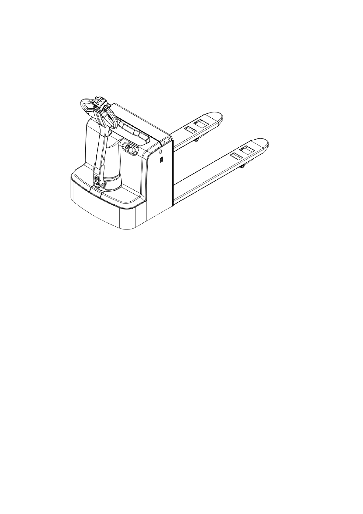
3.Introduction of the product .........................................................................................3
3.1 Model Overview .................................................................................................................3
4.Operating principle.........................................................................................................5
5.Operating principle.........................................................................................................6
5.1Running system...................................................................................................................6
5.2 Steering system ..................................................................................................................6
5.3 Braking system...................................................................................................................6
5.4 Operating System ..............................................................................................................8
5.5 Electric System ...................................................................................................................8
5.6 Hydraulic principle...........................................................................................................8
6.Electrical Schematic Diagram......................................................................................9
7.Hydraulic Schematic Diagram..................................................................................10
8.Operating Instruction.................................................................................................. 11
8.1 Start, run and parking:.................................................................................................. 11
8.2The usage of emergency safety switch.................................................................... 11
8.3 The usage of horn button. ........................................................................................... 11
8.4 Battery capacity indicator........................................................................................... 11
8.5 Handling stacking operation...................................................................................... 12
9.Maintenance ...................................................................................................................13
9.1Safety procedures for repair and maintenance................................................... 13
9.2 Daily Maintenance.......................................................................................................... 14
9.3 Professional Maintenance Manual........................................................................... 14
9.4Maintenance, Recharging and Replacement of the accumulator ................. 16
10.Safety Precautions .....................................................................................................19
10.1 general rules .................................................................................................................. 19
10.2 Transportation and storage..................................................................................... 19
10.3 Check before Using...................................................................................................... 20
10.4 Safe Operation............................................................................................................... 20
11.Repair Manual .............................................................................................................23
11.1 Malfunction analysis................................................................................................... 23
11.2 preparation work before repair............................................................................. 24
11.3 check the oil content of hydraulic oil................................................................... 24
11.4 preparation work before use after maintenance............................................ 24
12. After-sales service..................................................................................................... 24

1
1.The Introduction
EP18D is a tramp type electric pallet truck.It adopts the advanced structure such as ring rod
lifting system and new ac controller,at same time it is equipped with high quality motor,
lithium battery and pump station motor.It has the characteristics of superior performance,
convenient operation, flexible steering, reliable braking, good dynamic performance, less
noise, less pollution and beautiful appearance.
This series truck is suitable for working on the smooth ground in warehouse,if not,please
don’t use it.
The service environment:
a. temperature not over +40℃,not under-10℃;
b. the gradient can’t over 3%;
c. when environment temperature at +40℃,the relative humidity can’t over 50%,At
low temperature,allow big relative humidity;
d. ground need hard and flat;
e. It is forbidden to use this car in corrosive environment such as flammable and
explosive or acid base.

2
2.Proper usage
Please using the electric pallet truck accord to this specification.
This is a tramp type electric pallet truck with autonomous control , lifting and lowering
is controlled by the handle button.Improper use can cause personal injury or machine
damage.Operators or operating companies need to ensure proper using,
The Truck needs to be used on a firm ,flat ,intact surface and suitable surface ,The truck
is designed for indoor use at room temperature from-10°C to +40°C
Use under light load without using permanent barriers or pits ,It is forbidden to operate
on the slpes .During Operation ,The goods must be placed approximately at the center of the
truck’s load center
Lifting or Carrying people is strictly prohibited ,If carried goods .The goods must fall on
the lifting point 。
It is prohibited to use this truck on lifting or loading ramps。
The rated capacity is marked on the capacity label or nameplate.And the operator must pay
attention to the warming signs and safety instructions
Operating lighting must be at lest 50LUX.
Modification
Any modification that may affect the truck rated capacity, stability or safety operations must
be approved in advance by the Truck’s original manufacturer or Its authorized Manufacturer
or its successor. This includes the effects of changes such as Braking ,steering ,Visibility and
the addition of removable accessories.
After the manufacturer or its successor approves the modification or change ,The capacity
name plate ,Label identification marks operation and maintenance manual must be changed
accordingly
Truck damage caused by not following Instruction will lose its warranty.

3
3.Introduction of the product
3.1 Model Overview
This specification is for EP18LI/EP20LI series 4000-4400LBS tramp type electric pallet
truck(follow as truck).
The type is“EP18LI/20LI—18/20 load capacity is 4000-4400LBS” meet the requirement of
JB/T8452-1996《Battery forklift model establishment method》.
3.2 Model

4
Mode
EP18LI
EP20LI
Lift
Electric
Electric
Drive
Electric
Electric
Load Capacity
(lbs)
4000
4400
Load centre distance
(in)
24
24
Wheel base
(in)
53
53
Lowered fork height
(in)
3.3
3.3
Lifting height
(in)
7.7
7.7
Overall length
(in)
67.2
67.2
Overall width
(in)
27.5
27.5
Fork size
(in)
2/6/48
2/6/48
Outside distance of fork
(in)
27
27
Turning radius
(in)
55
55
Lifting speed,laden/unladen
(in/s)
0.8/1.1
0.8/1.1
Lowering speed,laden/unladen
(in/s)
1.5/1.5
1.5/1.5
Max. Gradient performance
laden/unladen
(%)
8/15
8/15
Brake type
electromagnetic
electromagnetic
Drive motor
kw
0.75
0.75
Lift motor
kw
0.8
0.8
Lithium Battery voltage
V/Ah
24/40
24/60
Type of the drive motor
DC Motor speed
control
DC Motor speed
control
Noise level at operator sear
dB(A)
68
68
Service weight
(lbs)
650
680

5
4.Operating principle
With battery as power producer and controlled by electrical and hydraulic, trucks can do some
actions like walking, turning, pallet fork lift, etc.
1.Switch for lifting and lowering 2.Switch for driving 3.Belly switch
4.Horn

6
5.Operating principle
5.1Running system
The truck is powered by a battery, which is realized by controlling the AC motor on the drive
wheel.The speed of walking is realized by frequency conversion control motor speed, which is
controlled by the accelerator.
Gear box in the factory has been posited enough gear lubricating oil. And please change the gear
lubricating oil every 1000 hours under normal circumstances.
If you hear abnormal sound from gear box when using, please stop and check immediately. If
there are bearing failure or some problem in gear, please replace and repair them.
5.2 Steering system
The operating handle drives the rotation direction sensor which can send out the turn signals that
makes the truck turn around.
5.3 Braking system
5.3.1Braking performance depends on road conditions and vehicle load
conditions.
The brake function can be activated by the following ways:
Turn the travel switch (2) to "0" position or release the switch to make truck brake
until it stops.
With the driving switch (2) moving directly from one driving direction to the
opposite direction, the vehicle regenerates the brake until it begins to move in the
opposite direction.
The handle moves up and down to the braking area (' B ') and the vehicle brakes.If
the handle is released, the handle automatically moves to the upper braking area ('
B ') and the vehicle stops until it stops.

7
Belly switch (3) can prevent the operator will be squeezed, when vehicles are
driven towards (' Fw) encounters an obstacle, body touch belly to slow down or
start to switch
vehicles (' Bw) driven a short distance, then stop.If the handle is in the operating area
and the vehicle is not moving, please consider that this is still working.
5.3.2Working principle of braking:
The brake is composed of magnetic yoke assembly 6, excitation coil 7, spring 2, brake disc 5,
armature 1, gear sleeve 4, mounting screw 3, etc.The brake is mounted on the end cover of the
motor and the mounting screw is adjusted to the specified air gap value.The gear sleeve is fixed on
the shaft, and its outer tooth is matched with the inner tooth of the brake disc. When working,
torque is transferred, and the brake disc can move axially on the gear sleeve.
When the brake excitation coil 7 is energized, the magnetic field generated by the coil
causes the armature 1 to attract to the yoke assembly 6, and the armature 1 is detached (released)
from the brake disc 5.At this time the motor drive shaft with brake disc 5 normal start and
operation.When coil 7 is cut off, the magnetic flux disappears and armature 1 is released. Spring 2
presses armature 1 and compresses the friction plate on the brake disc to generate friction, thus
achieving the braking purpose.
制动原理图

8
5.4 Operating System
The main working body of a moving truck is a cargo fork, which relies on a fork to carry the
pallet or cargo for transport and short distance transportation.The expansion of the cylinder
is realized by the control of the operating handle, and the pressure oil is provided by the
pumping station.
5.5 Electric System
The electrical system includes walking and operation control. The truck use AC electric
control assembly.。
The meter has a battery indicator .When the battery power is too low, the electric meter
will cut off the starting control line of the oil pump motor. The moving truck can only walk
without lifting the fork, and the prompt should be charged immediately. The motor of oil
pump is the dc motor for 5 minutes, so the pump motor is not suitable for long running. That
is, the lifting movement should have time interval, can not continuously carry on, otherwise
would make the motor heating, even burn.
Special note: when the truck is used for a long time, the starter of the oil pump motor
may fail, and it can't be broken after being sucked or closed. The latter is not throw control
handle, the oil pump motor is kept in the rotation, should immediately stop at this moment,
to cut off the power supply (unplug battery plug-in), make the oil pump motor stop running,
and promptly replace the starter.
5.6 Hydraulic principle
The oil pump motor drives the gear pump to provide hydraulic power,lifting oil cylinder is
responsible of fork’s lifting and lowering,The control of the lift oil road is controlled by the
buttons on the operating handle,The lifting action is controlled by a single action oil circuit
on the valve block.This model of the hydraulic system pressure can only be adjusted on the
valve block, has been debugging good, before they go out after they leave the our company
after-sales personnel or professional maintenance personnel are strictly forbidden to adjust
themselves, so as to avoid safety accident.

9
6.Electrical Schematic Diagram

10
7.Hydraulic Schematic Diagram

11
8.Operating Instruction
Before operation, please be familiar with the function of each switch/button on the
instrument panel.
8.1 Start, run and parking:
1).Insert the key into the key switch, turn to the right,pull the emergency power safety
switch up, open the control circuit.
2).Forks rise above ground about 3.93In.
3).Open the travel switch slowly,till the requested speed
4).Any fault of the truck happening during operation, need to cut off the power immediately,
and press the red emergency power switch down.
5).Avoid take a sudden turn during driving the truck.
6).Using truck Full load climbing a slope, need to know the condition of the slope, and press
the travel switch as much as possible to get a maximum grade ability.
7).When stop driving,put the fork in the bottom,press the emergency switch down, and pull
out the key.
8.2The usage of emergency safety switch
Press the emergency safety switch down,then the the truck’s power off. Method to open
it:pull the red button up.
Emergency safety switch is made of plastic, too much pressure may damage it.
8.3 The usage of horn button.
Press the horn button in the center of handle to notify people around.

12
8.4 Battery capacity indicator
The stacker battery capacity indicator has electricity capacity display function.
8.5 Handling stacking operation
1). How to transport the goods pile on weight
Will forklift drive to the front of the items which need to carry slowly , make fork parallel to
the ground, lifting the fork to height, it can be inserted into the freight insert goods fork and
move forward slowly, wen the goods completely inserted into the goods after parking and
stepping on the brakes, manipulating ascend handle, the heavy lifting to a certain height,
make the door frame lean back, slowly astern, don't touch the adjacent goods, when weight
completely left the heap of goods, reduce the goods to the right position, then walking for
handling.
2). The weight on the heap of goods
Will weight low, lean back door frame, to storage goods moving close to the pile of
deceleration, when determining forklift with pile goods into a linear state, stepping on the
brakes slowly adjust the door frame Angle to the vertical state, increase the weight will be
slightly more than goods pile height, and then slowly driving forklift driving forward to pile
top stop. Heap controls control lever slowly, once handling stacked drags the weight, the
goods fork to the hollow position, from the weight of the goods fork, make sure barrier-free
backward position, can retreat. After goods fork out weight reduce goods fork, door frame
round of the reentry after handling operation.

13
9.Maintenance
The parts on the vehicle, especially safety devices, shall not be modified without permission,
and the driving speed of the vehicle shall not be changed.All parts supplied by the original
manufacturer are subject to strict quality inspection.To ensure the safety and reliability of
the vehicle, please use the original accessories.Replacement parts, including all oil, must be
collected and processed in accordance with local environmental and health laws and
regulations.
9.1Safety procedures for repair and maintenance
Maintenance technician: The maintenance and service should only be performed by
special personnel trained by the manufacturer. After the technician sent by after-sales
department of the manufacturer completed maintenance and servicing work, they should
sign on the service log.
Cleaning Operation: Flammable liquid can not be used for cleaning the stacker. Before
cleaning, take safety precautions to prevent electric sparks (e.g. sparks caused by short
circuit). When operating the accumulator, connectors on it must be disconnected. Use soft
air suction or compressed air, non-conductive and anti-static brushes to clean electric and
electronic components.
Operation of Electric System: Operation on the electric system should only be performed
by specially trained personnel. Before performing any operation on the electric system,
precautions must be made to prevent electric shock. When operating the accumulator,
connectors on it must be disconnected.
Installation: When repairing or replacing hydraulic components, electric and electronic
components, make sure to install them back to their original positions.
Wheels:Quality of the wheels has significant effect on stability and driving performance of
the stacker. Modification on wheels can be performed only with the approval from the
manufacturer. When replacing wheels, ensure that the stacker is levelled as delivery
state(wheels must be replaced in pairs, i.e. replace right wheel together with left one).
Lifting chain and rollers: Chain and rollers will be worn quickly without good
lubrication.Perform periodic lubrication according to following maintenance table. Shorten

14
the lubrication period under adverse operation conditions (such as in dusty and hot
environment).
Hydraulic oil pipe: The oil pipe must be changed every 6 years. When change the hydraulic
assembled parts, the oil pipe should be also changed.
9.2 Daily Maintenance
9.2.1 Check every pole, every cable and their covers.
9.2.2Check if the accumulator box is secured.
9.2.3 Check the stacker for oil leakage.
9.2.4 Check the chain, rollers, fork, oil pipes and horn.
9.2.5Check the brake.
9.2.6 Check the wear and tear of drive wheels and loading wheels.
9.3 Professional Maintenance Manual
It is very important for safe operation of the truck to perform overall professional
maintenance. Failure in performing maintenance according to specified interval may cause
malfunction of the truck, and potential risk to human and equipment.
Maintenance periods listed in this manual apply to single shift a day under normal
operation conditions. If using in dusty environment, the ambient temperature varies
remarkably or in multi-shift situation, the maintenance period has to be shortened.
Maintain the truck according to following maintenance list. Maintenance periods are as
follows:
W1 = Every 50 work hours, but at least once a week.
M3 = Every 500 work hours, but at least once every three months
M6 = Every 1000 work hours, but at least once every six months
M12 = Every 2000 work hours, but at least once every 12 months
Additional operations should be performed in trial run period:
(In initial 50 –100 working hours or after two months)
—Check the nuts on the wheels, and tighten them if necessary.
—Check the hydraulic components for leakage, and tighten them if necessary.

15
—Replace the hydraulic filter.

16
9.4Maintenance, Recharging and Replacement of the
accumulator
The Lithium Iron Pallet Jack must be parked in a safe location before any operation on the
accumulator.
9.4.1 Maintenance Technician
Battery charging, maintenance and replacement must be operated by qualified
professionals.The user manual, supply preparation and charging requirements must be
carefully read before the preparation operation.
9.4.2 Fire protection measures
When operating the battery, smoking and open flame are strictly prohibited.Storage
batteries and charging should be kept away from combustible materials, and should be kept
at least 2 meters away. Places where batteries are placed should be well ventilated and
equipped with fire protection facilities.
9.4.3 Battery type and usage note
a. The battery type of the car is: lithium ion battery; Battery voltage 24V; This
battery belongs to environmental protection battery, without chemical mercury and
cadmium.
b. Matters needing attention:
1) the battery USES the temperature environment 5 ~ 45;
2) the battery shall be charged and discharged once every three months during the long
period of suspension;
3) before using the new battery, or for the first time after storage, please recharge the
battery before use;
4) do not short-circuit the battery, which may permanently damage the battery;
5) do not burn or destroy batteries, which may cause the release or explosion of toxic
gases;
6) do not directly weld the battery;
7) do not allow the battery to be in a hostile environment, such as extreme temperature,
deep cycle, or frequent overcharge/discharge;
8) if the battery is hot, do not touch, until cooling;

17
9) when removing the battery pack, hold the plug with your hand instead of pulling the
cord;
10) after the battery is used, if the battery is hot and before recharging, please cool in the
ventilated environment;
11) do not put batteries in water or seawater;
12) do not try to separate, squeeze, impact the battery, the battery will heat or fire, the
lye in the battery will be harmful to the skin and eyes, and will damage the clothes;
13) keep the battery away from children.
9.4.4 Disposition of worn-out accumulators
Worn-out accumulators should be recycled according to local regulations, and stored in
specified zone or cast-off treatment zone. These works should be done by qualified
specialized companies.
9.4.5 Specification of the battery
Battery
Charger
Rated power:24V
Rated capacity:
40-60Ah
Input :195/265VAC
50/60Hz
Output :
DC24V10A
The battery's non-insulated terminal must be protected by an insulating cover.When the
battery is connected and connected to the socket, the vehicle must be cut off and the switch
in the closed position.When replacing or assembling the battery, make sure the battery is
securely fixed in the battery box.
9.4.6 Storage, transportation and installation of the accumulator
The truck must be parked on the level ground steadily. To prevent short circuit,naked cable
ends and the terminal posts should be covered with insulated covers. When pulling out the
accumulator, properly arrange removed accumulator's connectors and cables without
blocking access of the accumulator.
9.4.7 Battery power indicator
Battery power display table:ten article showing represent 100% of the battery.With the
consumption of battery capacity, the glowing article shows will be from top to down.
The color of LED show the different states :
This manual suits for next models
1
Table of contents
Other EKKO Jack manuals
Popular Jack manuals by other brands

Tektronix
Tektronix Keithley HV-CS-1589 Installation information

Sealey
Sealey 2010HL instructions

kincrome
kincrome K12162 manual

Berger & Schröter
Berger & Schröter C56635 quick start guide

FISCHER
FISCHER 63298 Owner's manual & safety instructions

K Tool International
K Tool International XD KTI-63213A owner's manual