EKO INSTRUMENTS CO., LTD. Small Sensor ML-020 P/ML-020S-O/ML-020S-I Instruction Manual Ver.8 Pg. 7
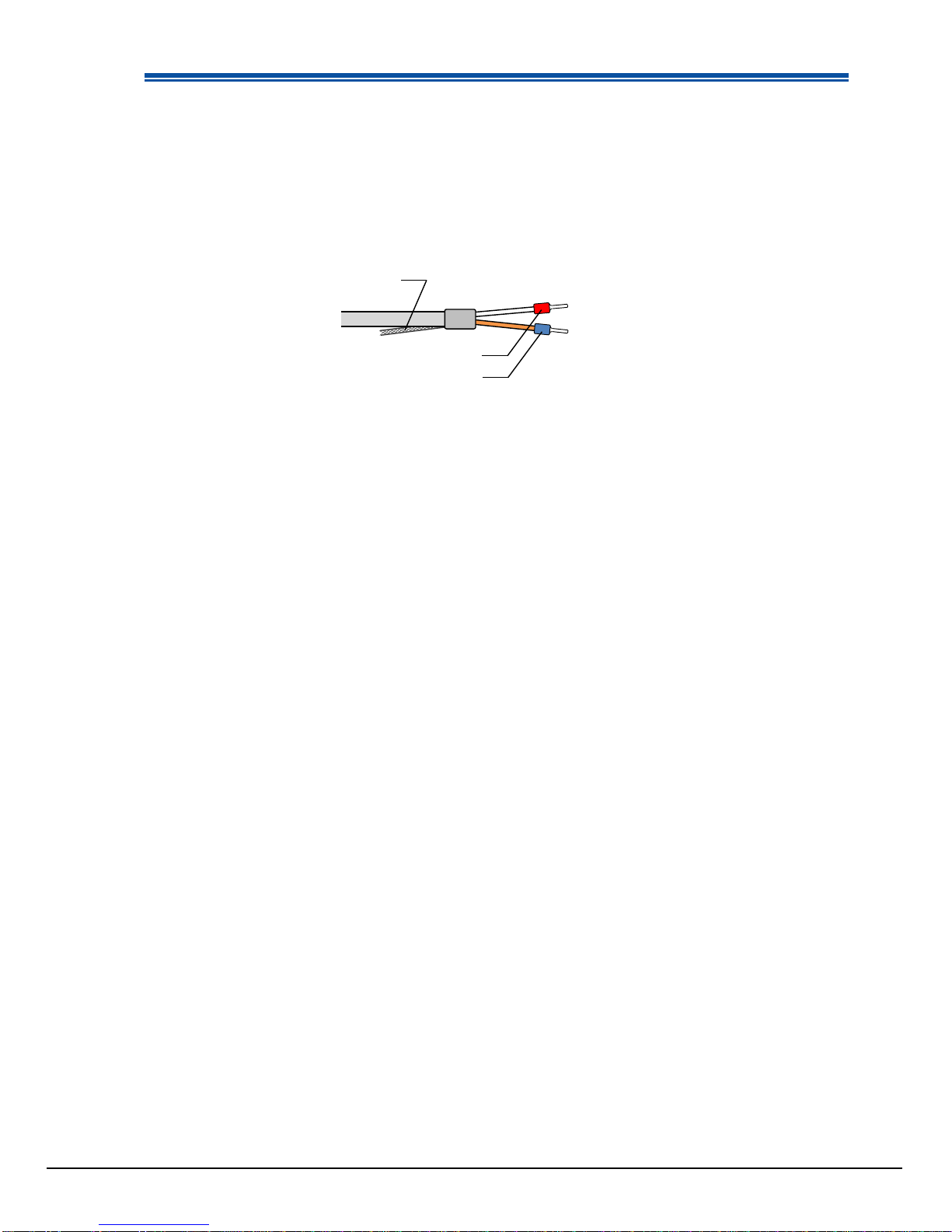
4. Cable
Small Sensors come with a single cable which is already attached and can be used right away.
At the end of signal cable has either a pin terminal for easier connection to measuring instruments such as
data logger. Standard length of the signal cable is 5m; other lengths (10m, 30m, 50m) are available on
request.
5-2. Setup
In order to obtain representative measurements working with the ML-020, several criteria with respect to
setup and mounting of the instruments have to be considered:
The ideal mounting position for solar sensors is a location which has a full hemispheric field-of-view without
any obstructions (such as buildings, trees, and mountain). In practice, it might be difficult to find such
locations. Therefore, some practical recommendations on how to minimize undesired effects of reflecting or
obstructing surfaces are given next:
Select a mounting position which it is free from obstructions at 5° above horizon.
The setup location should be easily accessible for periodic maintenance (glass dome cleaning,
desiccant replacement, etc.).
Avoid surrounding towers, poles, walls or billboards with bright colors that can reflect solar radiation
onto the pyranometer.
A strong physical impact to the pyranometer can lead to product damage and/or may cause changes
to the sensitivity.
1. Installing on Horizontal or Tilted Position
1) When installing the ML-020 without the optional leveling plate, three M2 screws must be prepared by
user.
Prepare three M2 screws that are 3~4mm longer than the installation base plate thickness which the
pyranometer is mounted.
2) Check the installation base where the sensor has to be mounted and make sure it has two fixing holes
with the appropriate pitch. (See [7-3. Dimension])
3) Setup the sensor with the signal cable facing the nearest Earth’s pole. In the Northern hemisphere, the
cable should be orientated North, in the Southern hemisphere, the cable should be orientated South.
4) [If optional Leveling Plate is used]
Adjust the 3 leveling screws on the leveling plate, so that the air bubble in the spirit level will be
positioned in the center of the circle on the spirit level. If the sensor is not leveled properly, the sensor
readings are affected by cosine and azimuth errors. Periodically check the spirit level and adjust the
sensor position if necessary.