FUE BED AYOUT
Please see the relevant section of the user instructions.
FITTING THE FIREFRONT
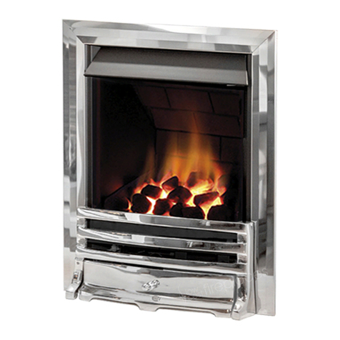
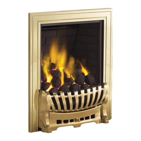
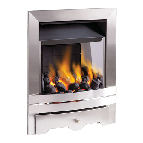
Place the decorative firefront in front of the fire and slide the ashpan door into place. The firefront shown in these instructions may be dif-
ferent to the one supplied with the appliance.
GAS CONNECTION
Purge the gas supply thoroughly to remove air and dirt/debris
BEFORE
connection. Now disconnect the inlet restrictor elbow from the inlet
pipe. Connect the previously installed gas supply to inlet restrictor elbow, and re-fit the restrictor elbow to the inlet pipe of the appliance.
If using an across hearth connection, ensure the decorative fireframe and firefront will clear the supply route.
If the data/control plate is not already fitted, attach with two screws, ensuring the control knob is free to be depressed fully.
TESTING AND COMMISSIONING
Turn on and test the gas supply up to the fire for any leaks, in accordance with current edition of BS6891.
When the appliance is first used, protective oils coating the firebox may burn off. It is advisable to ventilate the room during this period for
at least one hour.
OPERATING THE APP IANCE
The pilot is visible through the left hand side of ceramic front strip. When cold, the coals or peb-
bles may be rotated for good viewing.
The fire features a ‘twin spark’ ignition system to aid lighting, Push the control knob in fully and
turn anti-clockwise through both of the SPARK positions, keeping fully depressed, hold there for
a few seconds. If the fire has not been used for some time, hold the knob in this position for
longer, to allow any air in the pipes to be purged. Continue turning anti-clockwise through the
spark clicks to the nine o’clock position, ensuring the pilot has lit. If not, return the knob clock-
wise, and repeat. When the pilot lights after one of the two sparks, keep the knob depressed in
the nine o’clock position for approximately ten seconds. Now release the knob and the pilot
should stay alight. If the pilot is extinguished during use, wait three minutes before repeating the
ignition procedure.
To achieve the HIGH setting, push the control knob in slightly and continue turning anti-clockwise to the high position. The main burner
should light after a few seconds. To decrease the setting to OW, push the knob in slightly and turn the control knob clockwise to the low
setting. To turn to the pilot only position from the HIGH or OW positions, press the control knob in, and return to the nine o’clock position
and release. To turn the fire OFF, keep the knob pressed in, return to the off position and release.
SPARK FAI URE
The gap between the spark electrode and the pilot should be 3.5 - 4.5mm to produce a good spark. There should be no need to adjust this.
If under any circumstances the electric spark fails, the pilot may be lit manually by proceeding with the ignition sequence as previously
described, and after turning the control knob through the spark position, the knob should be held in and the pilot lit with a taper.
SETTING PRESSURE
Remove the screw from the pressure test point.
Manual control models : The pressure test point is located on the inlet isolation elbow.
Release the pressure test point screw, and attach a pressure gauge. ight the fire on the HIGH setting. To commission the appliance, the oper-
ating pressure must be in accordance with the figures stated in section 2.0 of these instructions. The fire is factory set to achieve the correct
flow rates at the specified operating pressure.
Any significant variation in the operating pressure could indicate a supply problem. If the operating pressure is too high, the gas supply
meter/governor may be set incorrectly. This should be checked with the fire running and if necessary reset by the gas supplier. If the oper-
ating pressure is too low, then check the meter/governor pressure with the appliance running. If this is less than the inlet pressure stated in
section 2.0 of these instructions it will need to be reset by the gas supplier. If the inlet pressure is too low, but the meter/governor pressure
is acceptable, then a problem in the supply pipework is to be suspected.
Upon satisfactory checking of the inlet pressure, turn the fire off, disconnect the pressure gauge and refit the test point screw. ight the fire
and check for gas soundness. In the event that the inlet pressure is not in accordance with the figures stated in the data section of these
instructions, the appliance must not be commissioned, and the problem investigated and rectified.
F UE SPI AGE MONITORING SYSTEM
This fire is fitted with a flue spillage safety device (ODS). If the fire shuts down during use for no apparent reason then several things may be
suspected. If a door or window has been opened creating a draught, then pilot disturbance is the problem, and removal of the draught should
resolve this. The gas pressure reaching the fire must also be checked (again, recall your installer to check and rectify any problem). The ther-
mocouple connection into the back of the gas control valve may also have worked loose during installation, simply get the installer to tight-
en. If pilot disturbance is not the cause, then the ODS safety system may be in operation. Switch the appliance OFF, check the flue and carry
out any remedial work required. Relight the fire and carry out a spillage test. DO NOT allow the appliance to be used if it continues to fail a
spillage test.
