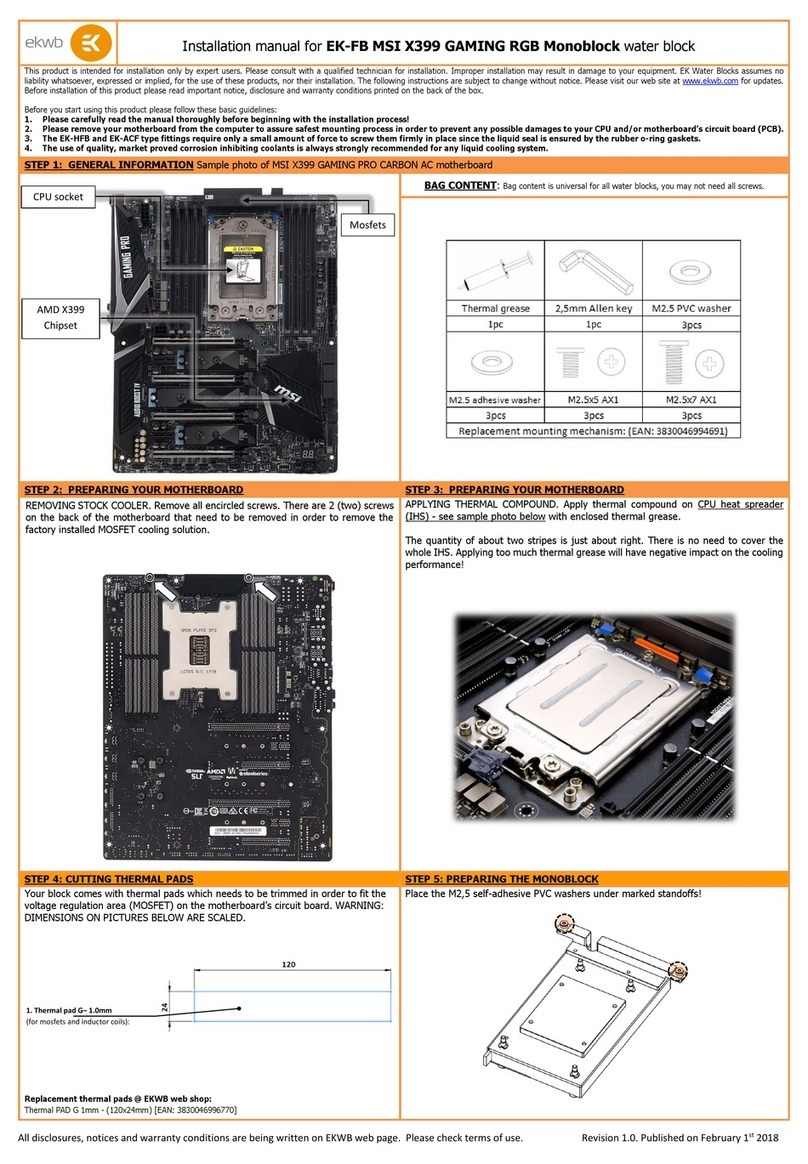
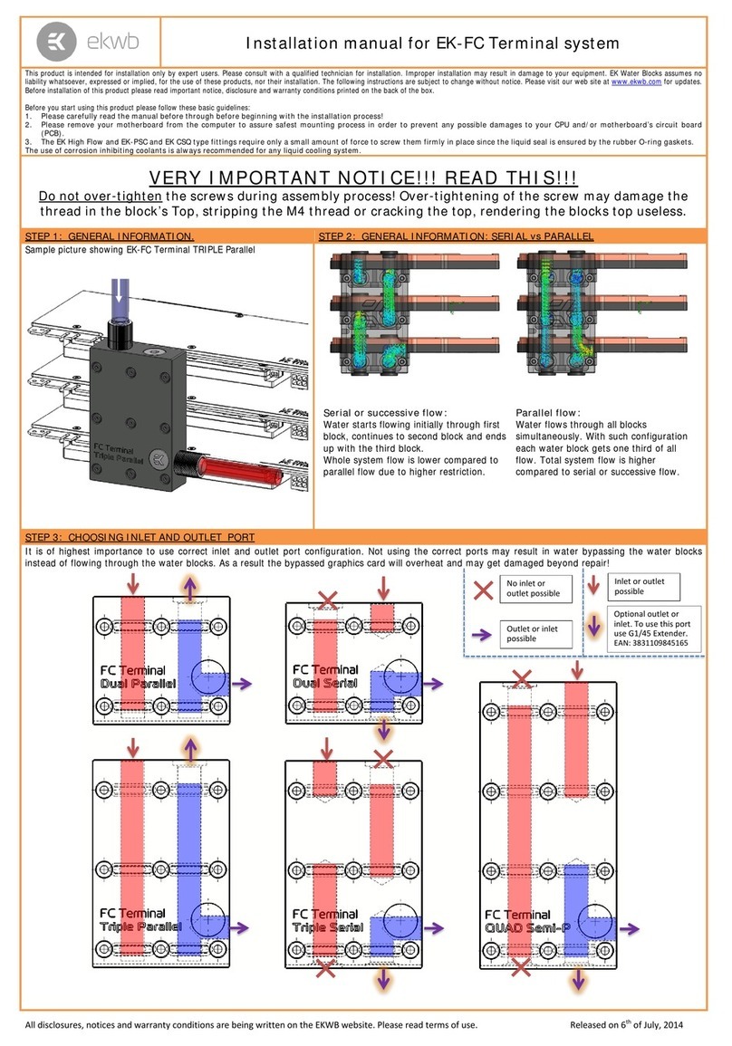
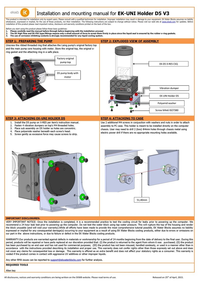
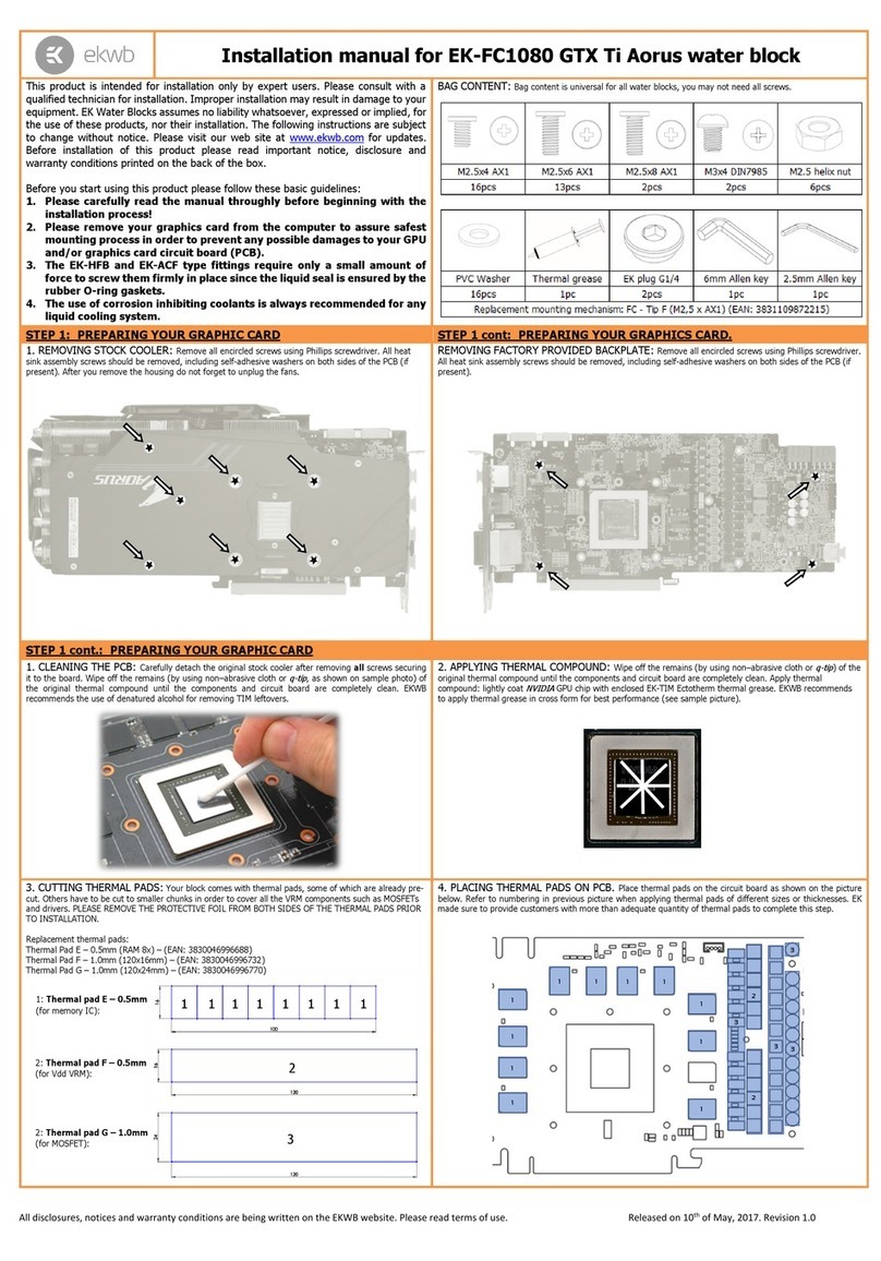
manuals.online logo
Brands
  1. Home
  2. •
  3. Brands
  4. •
  5. ekwb
  6. •
  7. Computer Hardware
  8. •
  9. ekwb Barebones Guide

ekwb Barebones Guide

EK-Liquid Cooling Barebone
& Lian Li PC-O11 Dynamic D-RGB
Congratulations on taking your first steps into liquid cooling with the EK Barebones Kit, designed from the ground up by our
expert team of engineers to be an easy to follow set of instructions that will walk you through every step to assemble your
first liquid cooled masterpiece. The following step by step guide will walk you through installing the included water blocks on
your preferred CPU and GPU, and wrapping it all up with assembling your full custom loop in the Lian-LI PC-011 Dynamic Chassis.
Thank you for choosing EK for your Liquid cooling solution, if you run into any issues please don’t hesitate to contact our first-class Support.
Please note coolant is NOT included with the EK Barebones Kit and is required BEFORE starting your PC. We recommend 2 Liters of
EK-CryoFuel in your choice of color (CryoFuel solid is not compatible)
INSTALLATION AND ASSEMBLY GUIDE
PLEASE READ FIRST
Check the latest version of this installation
guide by scanning the QR code below.
These instructions apply to both versions of the Barebones:
Barebone - basic Barebone - upgraded version
Distribution Plate
Additional
Radiator
DDC Pump
Additional Fans (mounted by the customer)
SPC Pump
Radiator Fans
Additional
Fans
EK-Liquid Cooling Barebone & Lian Li PC-O11 Dynamic D-RGB
Assembly Instructions
Your new EK-Liquid Cooling Barebone & Lian Li PC-O11 Dynamic D-RGB is already partly assembled with the radiator, fans, pump
and reservoir securely fitted and tested. All that’s left for you to do now is install your chosen components and fill the loop!
Please, read this entire guide before starting to assemble your computer. We recommend you install each component in the order
outlined in this guide for the safest and most beneficial results.
Tubes for the CPU may need to be shortened to the appropriate length.
You will find a list of supported motherboards below.
Caution
The following motherboard compatibility list is mostly based on visual verification, so keep in mind that the vertical CPU placement could
vary on some motherboards, but not more than 3 – 5mm in any direction.
Z390 / Z370
ASUS Z390 Strix-E
ASUS Z370 Strix-E
ASUS Z370 Maximus X Hero
ASUS Z370 Maximus X Apex
MSI Z370 Godlike
X470
ASUS ROG STRIX X470-F GAMING (3-5mm)
ASUS PRIME X470-PRO (3-5mm)
ASUS TUF X470-PLUS GAMING (3-5mm)
MSI X470 GAMING M7 AC
MSI X470 GAMING PRO CARBON AC
MSI X470 GAMING PRO CARBON
MSI X470 GAMING PRO (3-5mm)
MSI X470 GAMING PLUS (3-5mm)
MSI X470 GAMING PRO MAX (3-5mm)
MSI X470 GAMING PLUS MAX (3-5mm)
X570
ASUS PRIME X570-PRO (3-5mm)
ASUS PRIME X570-PRO/CSM (3-5mm)
ASUS ROG CROSSHAIR VIII HERO (WI-FI) (3-5mm)
ASUS ROG STRIX X570-F GAMING (3-5mm)
ASUS ROG STRIX X570-E (3-5mm)
ASUS TUF GAMING X570-PLUS (WI-FI) (3-5mm)
ASUS TUF GAMING X570-PLUS (3-5mm)
MSI MPG X570 GAMING EDGE WIFI
MSI MEG X570 ACE
MSI MEG X570 UNIFY
MSI MPG X570 GAMING PLUS
MSI X570-A PRO
MSI MPG X570 GAMING PRO CARBON WIFI (3-5mm)
MSI MEG X570 GODLIKE (3-5mm)
MSI PRESTIGE X570 CREATION (3-5mm)
CONTENTS
I. CPU Intel 115x – Assembly 7
II. CPU AMD AM4 – Assembly 9
III. GPU – ASSEMBLY 11
IV. FINAL ASSEMBLY 12
7
STEP 4
I. CPU INTEL 115X – ASSEMBLY
STEP 1
Install your CPU and any M.2 drives in accordance with the instructions in
your motherboard manual and then place the mother-board face down on an
even surface.
STEP 2
Preparing backplate rubber gasket: The enclosed rubber gasket is an
essential part of the backplate and mounting system and must be used every
time you install this water block on your motherboard.
The rubber gasket has a partially cut inner part which needs to be removed
when installed on Intel® LGA-115x motherboard. The rubber is held in four
places and can be peeled away by hand.
STEP 3
Install backplate rubber gasket and place metal backplate for Intel LGA-115x
socket to the back of your motherboard RIBBED SIDE UP.(facing away
from the motherboard) Align the holes on the motherboard with holes on
rubber gasket and backplate.
Make sure to align the rubber gasket to fit past the CPU socket ILM backplate.
Carefully rotate the motherboard assembly, front side facing up, with one hand
while holding the backplate and rubber in place with the other hand.
STEP 4
Install four (4) thumb screws onto your motherboard. It is mandatory to put
plastic washer underneath each of the M4 thumb screws. Tighten the screws
to the metal backplate until you reach the end of the thread. Using tools (such
as pliers) is not recommended.
STEP 5
Cleaning the CPU: Wipe the CPU’s contact surface (using the non-abrasive
cloth or Q-tip, as shown in the sample photo).
Applying the thermal compound: EK recommends blob or line method of
applying the enclosed thermal compound to the CPU heat spreader (IHS) -
see sample photo on right.
The quantity of about two rice grains is just about right. There is no need to
cover the whole IHS. Applying too much thermal grease will have a negative
impact on cooling performance!
Thumb Screw
Plastic
Washer
STEP 2
Outer Part
Inner Core
(removable)
Rubber
gasket
Motherboard Metal
Backplate
STEP 3
Non-abrasive
Cloth
IHS
STEP 5
I. CPU Intel 115x – Assembly
8
STEP 6
Before proceeding with the installation It is mandatory to remove the protective
foil from the backside of the water block.
Align the water block over the mounting screws on the motherboard and posi-
tion it on top of the CPU.
Place an enclosed compression spring and a thumb nut over each of the M4
thumb screws. Tighten the screws evenly by fastening two opposing nuts at the
same time. Do not tighten them fully until all four have been installed. Then – using
your fingers only – screw in all four thumb nuts until you reach the end of thread.
STEP 7
Install a pair of ALU 25mm Extender fittings onto your CPU block. Tighten in a
clockwise direction until the seal underneath is compressed.
STEP 8
Install your RAM modules as prescribed in the motherboard instructions along
with any additional parts that are mounted directly to the motherboard.
STEP 6
Thumb nut
Coiled spring
STEP 7
I. CPU Intel 115x – Assembly
ALU 25mm
Extender fitting
9
II. CPU AMD AM4 – Assembly
II. CPU AMD AM4 – ASSEMBLY
STEP 1
Removing of the original plastic hold-down clamps and the factory
backplate:
Using Philips-head screwdriver remove the four UNC 6-32 screws securing the
original plastic hold-down clamps around the socket as shown on the sketch.
Remove the original AMD® backplate and the hold-down clamps and store
them away. See sketch for further part identification.
STEP 2
Preparing backplate rubber gasket
The enclosed rubber gasket is essential part of the backplate and mounting
system and must be used every time you install this water block on your
motherboard.
With AMD® Sockets you should use whole rubber backplate in-
cluding the inner core.
STEP 3
Install backplate rubber gasket and place metal backplate for AMD® socket
to the back of your motherboard RIBBED SIDE UP. (facing away from the
motherboard) Align the holes on the motherboard with holes on rubber gasket
and backplate.
Carefully rotate motherboard assembly with front side facing up with one hand
while holding the backplate and rubber in place with the other hand.
STEP 4
Install four (4) thumb screws onto your motherboard. It is mandatory to put plas-
tic washer underneath each of the thumb screws. Tighten the screws to the
metal backplate until you reach the end of the thread. Using tools (such as pliers)
is not recommended.
AM4
Metal
Backplate
Rubber
gasket
Motherboard
AMD® factory Backplate
UNC 6-32
Screws
Hold-down
Clamps
Outer Part
Inner Core
(removable)
STEP 1
STEP 3
STEP 4
Plastic Washer
Thumb Screw
STEP 2
10
STEP 5
Cleaning the CPU: Wipe the CPU’s contact surface (using the non-abrasive
cloth or Q-tip, as shown in the sample photo).
Applying the thermal compound: EK recommends blob or line method
of applying the enclosed thermal compound to the CPU heat spreader (IHS)
- see sample photo on right.
The quantity of about two rice grains is just about right. There is no need to
cover the whole IHS. Applying too much thermal grease will have a negative
impact on cooling performance!
Non-abrasive
Cloth
IHS
STEP 5
II. CPU AMD AM4 – Assembly
STEP 6
Before proceeding with the installation it is mandatory to remove the protective
foil from the backside of the water block.
Align the water block over the mounting screws on the motherboard and
position it on top of the CPU.
Place an enclosed compression spring and a thumb nut over each of the
thumb screws. Tighten the screws evenly by fastening two opposing nuts
at the same time. Do not tighten them fully until all four have been installed.
Then – using your fingers only – screw in all four thumb nuts until you reach
the end of thread.
STEP 6
Thumb nut
Coiled spring
STEP 7
Install a pair of ALU 25mm Extender fittings onto your CPU block. Tighten in a
clockwise direction until the seal underneath is compressed.
STEP 8
Install your RAM modules as prescribed in the motherboard instructions along
with any additional parts that are mounted directly to the motherboard.
STEP 7
ALU 25mm
Extender Fitting
11
III. GPU – ASSEMBLY
To install the water block and backplate to your graphics card follow the
specific installation manual. It is available by scanning the appropriate QR code.
Alternatively, you can type the link in a web browser or you can go to the EK
shop and search for the installation manual there by typing the name of your
GPU block in the search box.
I M PO R TA N T:
When you follow the instructions for assembling the water block from the link,
skip these two steps:
- INSTALLATION OF FITTINGS AND TUBING
- CONNECTING THE D-RGB LED STRIP
And continue to follow the instructions from this installation manual with step 2.
III. GPU – Assembly
EK-AC Radeon RX 6800/6900 D-RGB
GPU Waterblock & Backplate:
https://www.ekwb.com/shop/EK-IM/EK-IM-3831109834930.pdf
EK-AC GeForce RTX 3080/3090 D-RGB
GPU Waterblock:
https://www.ekwb.com/shop/EK-IM/EK-IM-3831109833698.pdf
EK-AC GeForce RTX 3080/3090 – Backplate
Backplate:
https://www.ekwb.com/shop/EK-IM/EK-IM-3831109833674.pdf
EK-AC Trinity RTX 3080/3090 – Backplate
Backplate:
https://www.ekwb.com/shop/EK-IM/EK-IM-3831109833681.pdf
EK-AC Twin Edge RTX 3070 D-RGB
GPU Waterblock & Backplate:
https://www.ekwb.com/shop/EK-IM/EK-IM-3831109835555.pdf
EK-AC TUF RTX 3060/3060TI/3070 D-RGB
GPU Waterblock & Backplate:
https://www.ekwb.com/shop/EK-IM/EK-IM-3831109848555.pdf
EK-AC Radeon RX 6700 XT D-RGB
GPU Waterblock & Backplate:
https://www.ekwb.com/shop/EK-IM/EK-IM-3831109848548.pdf
12
IV. FINAL ASSEMBLY
STEP 1
Remove the remaining panels from the chassis and unscrew each ALU-HDC
compression ring from the distribution plate. Put the 4 loose O-rings to the side
until tube installation.
By default, the distribution plate is configured for the most common Intel/AMD
mainstream motherboards that use slot 2 for the primary graphics card. If this is
required to be in slot 1 for your motherboard, then you may configure the fittings
and stop plugs accordingly. The lower two are GPU IN ports and the upper two
are GPU OUT ports.
STEP 2
Install the motherboard I/O shield to the chassis and insert your motherboard
complete with all parts outlined in Section I. Fasten it in place using the
screws supplied with the chassis and route the CPU block D-RGB cable
into the rear compartment.
STEP 3
Remove the appropriate PCI slot covers and install the water blocked graphics
card from Section II. Make sure that it is correctly inserted into the slot and
secured to the chassis with the supplied thumb screws.
STEP 1
V. Final Assembly
CPU IN
CPU OUT
GPU IN
GPU OUT
STEP 5
MEASUREMENTS FOR CONNECTING THE TUBES TO
THE CPU BLOCK
Measure the vertical and horizontal distance between the ports on the CPU
block and distribution plate.
To measure vertical alignment, use one of the straight tubes and measure
approximate vertical variance.
If the CPU water block’s vertical position aligns with the Distribution Plate CPU
ports or it is smaller than 5mm (0.2 inches), please use straight tubes only
and proceed to step 7.
If the vertical position of the CPU block is more than 5mm (0.2 inches) miss-
aligned, please proceed to step 6.
STEP 4
Since the horizontal and vertical placement of the CPU block varies on
different mother-boards, we have enclosed four (4) straight tubes and
two (2) pre-bent tubes to make the Barebone KIT compatible with the
motherboard you have purchased.
For the CPU block, two tubes are pre-bent and allow up to +-12 mm height variance.
STEP 4
max 12 mm
pre-bent Tubes (2x)
STEP 5
Horizontal Distance
Distribution Plate
Vertical
Distance
CPU Block
Check with straight tube
for vertical alignment.
13
STEP 6
USE AND CUTTING OF PRE-BENT TUBES FOR ALIGNING
CPU BLOCK TUBES WITH DISTRIBUTION PLATE
Once you have measured the vertical variance, cut the tube according to the
following instructions:
Variance mm / Inch Cut following length of the short end
bend (1st CUT):
5mm (0.2”) 41mm (1.6”)
6mm (0.24”) 35mm (1.4”)
7mm (0.28”) 29mm (1.14”)
8mm (0.31”) 24mm (0.95”)
9mm (0.35”) 18mm (0.7”)
10mm (0.39”) 12mm (0.5”)
11mm (0.43“) 6mm (0.24”)
12mm (0.47”) Don’t cut anything on this end
Use the miter tool to cut the tube straight.
When measuring the length of the tube, please follow these steps:
1. Measure the horizontal distance from the Distribution Plate surface to the
center of the CPU block fitting.
2. Deduct from that length 16 mm (0.63“).
3. Cut the tube at that length.
Vertical variance:
1st CUT:
6mm (0.24")
12 mm (0.5")
18 mm (0.7")
24 mm (0.95")
29 mm (1.14")
35 mm (1.4")
41 mm (1.6")
5 mm (0.2")
6 mm (0.24")
7 mm (0.28")
8 mm (0.31")
9 mm (0.35")
10 mm (0.39")
11 mm (0.43")
12 mm (0.47") - dont cut
STEP 6
STEP 6 First Cut
Miter Tool
STEP 6
If vertical
distance is
bigger than
5 mm
Distribution Plate
CPU Block
First Cut
Second Cut
STEP 6 Second Cut
Miter Tool
[Horizontal distance] - [16 mm (0.63”)]
V. Final Assembly
14
STEP 10
STEP 10
Put the assembled tubes, fittings and adapters into the build. First, slide the
compression ring and O-ring over the tube and push the tube into the distribution
plate fitting. Leave the compression rings loose for now.
STEP 9
STEP 9
Remove the compression ring and upper O-ring (loose) from an ALU-HDC
fitting and screw the inner part tightly into an ALU-AF 90° adapter. Slide the
compression ring and O-ring over the tube, push the tube firmly inside the fitting
until it stops and finally tighten the compression ring. Repeat this process for all
four enclosed tubes, installing the fitting and adapter on one end only.
STEP 7
CUTTING STRAIGHT TUBES FOR THE CPU BLOCK
If there is no vertical variance or if it is smaller than 5 mm you just need to
make one cut at the correct length to get the exact horizontal length of the
straight tube.
Use the miter tool to cut the straight tube.
1. Measure the horizontal distance from the Distribution Plate surface to the
center of the CPU block fitting.
2. Deduct from that length 16 mm (0.63”).
3. Cut the tube at that length.
We strongly advise that you cut in increments to prevent any
miscalculation that could result in cutting the tube too short.
Starting with a longer cut and trimming in short increments will
ensure that you have the correct fit.
The two prebent tubes can also be used as spares for straight tubes as the
straight part is long enough for the connection.
STEP 7
Horizontal Distance
Distribution Plate
CPU Block
STEP 7 One Cut
Miter Tool
STEP 8
Use the tube reamer or sandpaper to chamfer the edges on all tubes for easier
installation into the fittings and to avoid damaging the o-ring.
STEP 8
V. Final Assembly
[Horizontal distance] - [16 mm (0.63”)]
15
STEP 11
Screw the adapters into each water block port by rotating the knurled section.
Tighten in a clockwise direction until the seal underneath is compressed.
STEP 12
Now tighten the compression rings on the distribution plate to complete the
loop and secure all of the tubing in place.
For this step you will need:
See image of your specific
GPU block below.
See image of your specific
GPU block below.
STEP 13
INSTALLATION OF TUBES FOR GPU BLOCK
Assemble both of the pre-cut tubes from the GPU pack as shown in the
image for your specific GPU block. For detailed instructions about how to
install tubes with fittings, see STEP 9 to STEP 12 on pages 14 and 15. Be
sure to orient the tubes correctly during the installation and that you use the
correct fittings.
ATTENTION: Do not cut the tubes for the GPU block because
they are pre-cut.
STEP 11
STEP 12
V. Final Assembly
ALU-AF 90° adapter (2 pcs) ALU-HDC fitting (4 pcs) GPU tube 1 (1 piece) GPU tube 2 (1 piece)
16
EK-AC GeForce RTX 3080/3090 D-RGB
V. Final Assembly
STEP 13
ALU-HDC
Fitting
1
1
2
2
ALU-AF 90°
Adapter
GPU side Distribution
Plate side
ALU-HDC
Fitting
EK-AC Radeon RX 6800/6900 D-RGB
STEP 13
1
1
2
2
GPU side Distribution
Plate side
17
EK-AC Twin Edge RTX 3070 D-RGB
STEP 13
1
1
2
2
GPU side
Distribution
Plate side
EK-AC TUF RTX 3060/3060TI/3070 D-RGB
STEP 13
1
2
2
1
Distribution Plate
side
V. Final Assembly
GPU side
18
STEP 14 – only applies to “Barebone - upgraded version”
Use eight Self-Tapping Fan Mounting Screws to install two fans onto the
chassis.
STEP 14
EK-AC Radeon RX 6700 XT D-RGB
STEP 13
1
2
V. Final Assembly
1
2
GPU side Distribution
Plate side
Self-Tapping Fan Mounting Screws
(8 pcs)
STEP 15
Before installing any cables or further components, it is advised that you bleed
and inspect the cooling components. Fill the provided bottle with mixed coolant
and begin to fill the system using the top port on the outside of the chassis.
STEP 16
Install your PSU into the chassis and connect the supplied bridging plug. Use the
SATA to 3-pin adapter to power the pump and run it until the coolant level drops.
Refill the reservoir and repeat the process until all air is purged from the loop. This
process will be faster if the chassis is leaned over in different orientations and the
pump is cycled on and off.
Inspect all of the tubing and fittings before proceeding.
Do not run the pump without coolant! This will lead to premature failure as
the pump itself is lubricated and cooled by the coolant.
STEP 17
Remove the bridging plug and install any additional components you may have
such as drives or expansion cards. Connect all power, fan, pump, and D-RGB
cables to your motherboard using the provided splitters and extensions. All RGB
enabled devices are digital and should not be installed into 12V RGB connectors
as this will result in immediate damage. Pay attention to the marked orientation
on each and every connector.
EK advises that you connect the pump directly to your CPU FAN header and
set a static PWM speed between 60 and 100% if RPM control and monitoring
is desired. Otherwise, the supplied SATA power adapter will be suitable for
permanent use. The radiator fans may be configured dynamically or statically to
meet your expectations of thermal and acoustic performance.
Replace all of the chassis panels and enjoy your new amazing EK Fully
Liquid Coooled PC!
STEP 15
STEP 16
EK-ATX Bridging
Plug
Power supply ATX Cable
V. Final Assembly
Need help with this product?
Visit us at: www.ekwb.com/support
Or e-mail us at: support@ekwb.com
For hardware compatibility please visit: www.ekcoolingconfigurator.com

Other ekwb Computer Hardware manuals

ekwb EK H30 SUPREME User manual

ekwb

ekwb EK H30 SUPREME User manual

ekwb EK-FC980 GTX Ti Classy KPE Series Manual

ekwb

ekwb EK-FC980 GTX Ti Classy KPE Series Manual

ekwb EK-FB GA AX370 Gaming RGB Monoblock User manual

ekwb

ekwb EK-FB GA AX370 Gaming RGB Monoblock User manual

ekwb EK-FB ASUS M5E Guide

ekwb

ekwb EK-FB ASUS M5E Guide

ekwb EK-Classic GPU Water Block RTX 3080/3090... User manual

ekwb

ekwb EK-Classic GPU Water Block RTX 3080/3090... User manual

ekwb EK-Vector Radeon VII User manual

ekwb

ekwb EK-Vector Radeon VII User manual

ekwb EK-FC980 GTX Ti Strix Manual

ekwb

ekwb EK-FC980 GTX Ti Strix Manual

ekwb EK-FC980 GTX Classy KPE Backplate Guide

ekwb

ekwb EK-FC980 GTX Classy KPE Backplate Guide

ekwb EK-FB KIT GA X79 (UD7) Guide

ekwb

ekwb EK-FB KIT GA X79 (UD7) Guide

ekwb EK-FC R9-280X DCII User manual

ekwb

ekwb EK-FC R9-280X DCII User manual

ekwb EK-Quantum Velocity 2 User manual

ekwb

ekwb EK-Quantum Velocity 2 User manual

ekwb EK-Quantum Vector2 Trio RTX 3080/90 ABP Set... User manual
ekwb

ekwb EK-Quantum Vector2 Trio RTX 3080/90 ABP Set... User manual

ekwb EK-XTOP D5 Guide

ekwb

ekwb EK-XTOP D5 Guide

ekwb EK-Quantum Momentum2 ROG Strix Z690-I Gaming D-RGB -... User manual

ekwb

ekwb EK-Quantum Momentum2 ROG Strix Z690-I Gaming D-RGB -... User manual

ekwb EK-FC R9 Nano Series Manual

ekwb

ekwb EK-FC R9 Nano Series Manual

ekwb EK-Quantum Vector2 Trio RTX 3080/90 ABP Set... User manual

ekwb

ekwb EK-Quantum Vector2 Trio RTX 3080/90 ABP Set... User manual

ekwb EK-FC780 GTX Ti Series User manual

ekwb

ekwb EK-FC780 GTX Ti Series User manual

ekwb EK-Vector Radeon RX5700 + XT Backplate User manual

ekwb

ekwb EK-Vector Radeon RX5700 + XT Backplate User manual

ekwb EK-Classic AM4 D-RGB User manual

ekwb

ekwb EK-Classic AM4 D-RGB User manual

ekwb EK-Annihilator Series User manual

ekwb

ekwb EK-Annihilator Series User manual

ekwb EK-FC285 GTX Classified Manual

ekwb

ekwb EK-FC285 GTX Classified Manual

ekwb EK-Quantum Reflection PC-O11D D5 PWM D-RGB User manual

ekwb

ekwb EK-Quantum Reflection PC-O11D D5 PWM D-RGB User manual

ekwb EK-FC WX9100 PRO BACKPLATE User manual

ekwb

ekwb EK-FC WX9100 PRO BACKPLATE User manual

ekwb EK-FB GA 990FXA-UD7 Manual

ekwb

ekwb EK-FB GA 990FXA-UD7 Manual

Popular Computer Hardware manuals by other brands

KWorld DVB-S 100 Features

KWorld

KWorld DVB-S 100 Features

NUROTRON Enduro manual

NUROTRON

NUROTRON Enduro manual

ND&M ACCUMULATING FRAMEGRABBER operating instructions

ND&M

ND&M ACCUMULATING FRAMEGRABBER operating instructions

Behringer MINIFEX FEX800 quick start guide

Behringer

Behringer MINIFEX FEX800 quick start guide

Intel Xeon Processor E5-2600 Software ecosystem support

Intel

Intel Xeon Processor E5-2600 Software ecosystem support

Rockwell Automation Trusted T8833 manual

Rockwell Automation

Rockwell Automation Trusted T8833 manual

StarTech.com ISA1S550 instruction manual

StarTech.com

StarTech.com ISA1S550 instruction manual

Alesis Classical Instruments Plus user guide

Alesis

Alesis Classical Instruments Plus user guide

Multitech ISI5634PCI/4/8 user guide

Multitech

Multitech ISI5634PCI/4/8 user guide

IDTECH Xpress CM200 Operation guidelines

IDTECH

IDTECH Xpress CM200 Operation guidelines

digi-tech RP70 owner's manual

digi-tech

digi-tech RP70 owner's manual

Multitech MultiModem ISI9234HPCIE user guide

Multitech

Multitech MultiModem ISI9234HPCIE user guide

AirLive AirVideo-100v2 user manual

AirLive

AirLive AirVideo-100v2 user manual

InWin IW-RS104-07 user manual

InWin

InWin IW-RS104-07 user manual

Dynalab MTH-103E Installation and operation manual

Dynalab

Dynalab MTH-103E Installation and operation manual

Asus Aaeon BOXER-8641AI user manual

Asus

Asus Aaeon BOXER-8641AI user manual

TV One C2-1000 Series Operation manual

TV One

TV One C2-1000 Series Operation manual

digi-tech RP355 owner's manual

digi-tech

digi-tech RP355 owner's manual

manuals.online logo
manuals.online logoBrands
  • About & Mission
  • Contact us
  • Privacy Policy
  • Terms and Conditions

Copyright 2025 Manuals.Online. All Rights Reserved.