1
2
3
4
51
2
3
4
5
POW ER IN:
100 -240V ~, 50/6 0Hz
FUS E:
T3. 15A 250V 5 x20mm
Pow er Cons umpti on:
90W m ax.
WARN ING: / ATTE NTION :
DRY LO CATION S
EMP LACEM ENTS SE CS
NOT F OR RESI DENTI AL / HOUSE HOLD US E.
PAS PO UR USAG E RESID ENTIE L / M ENAGE .
RIS K OF FIRE AN D ELECT RIC SHO CK
RIS QUE DE CH OC ELEC TRIQU E ET INCE NDIE
O
FOR SUPPLY CO NNECTIONS USE W ITH WIRE RATED AT LEAST 60 C
POUR LES C ONNEXIONS D' ALIMENTATION DE FIL D'U NE NOTATION
O
MINIMAL E DE 60 C
MINIMU M SAFETY DISTANCE TO FL AMMABLE MATERI ALS: 0.2m.
DISTANCE DE S ECURITE AUX MATERIAU X COMBUSTI BLES: 0.2m.
O
MAXIMU M OPERATING TEMPE RATURE OF ENCLOSU RE SURFACE IS 60 C
O
TEMPER ATURE DE FON CTIONNEMEN T DE SURFACE ENCEIN TE EST A 60 C
FUSE
POWER
MOD E MEN U
RDM/ DMX
POWE R
UP DO WN
Mad e in Chin a
RDM /DMX OU T
POW ER THRU (15A Max .)
Ear th
Neu tra l
Liv e
RDM /DMX IN
POW ER IN(1 5A Max.)
Ear th
Neu tra l
Liv e
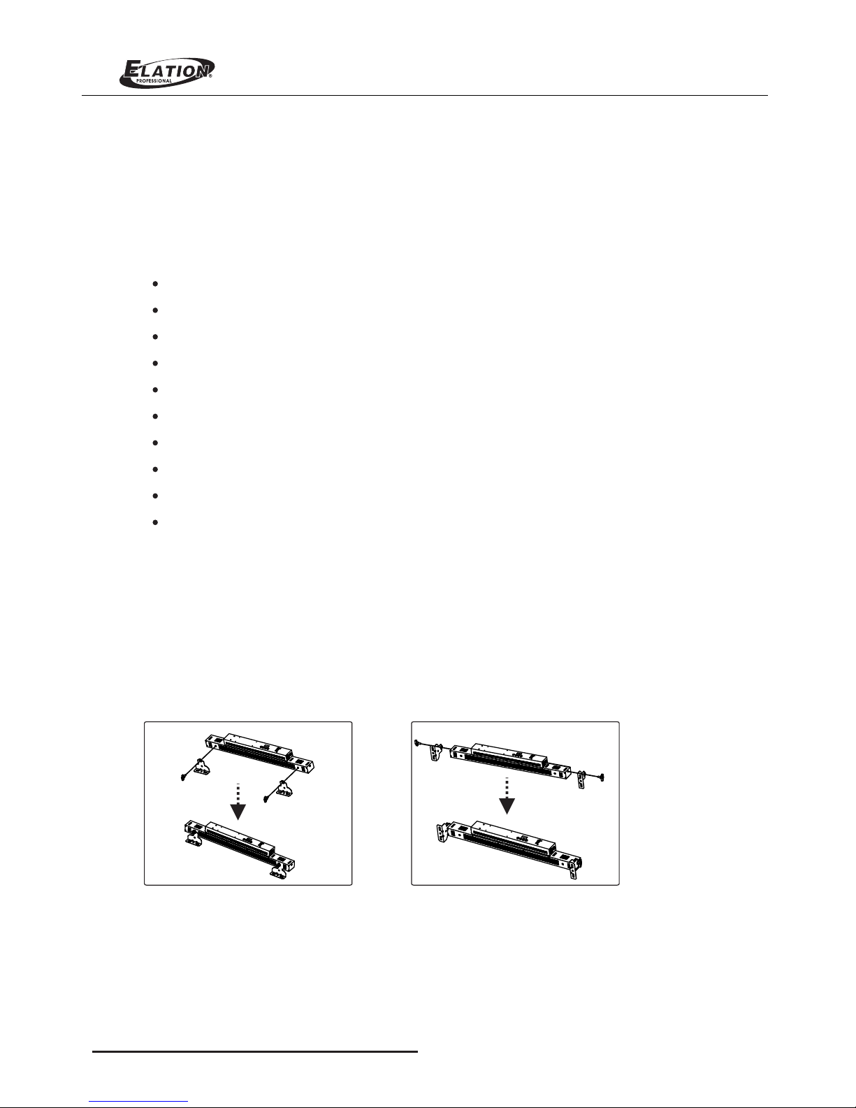
Safety chain/cord Safety chain/cord
attachment pointattachment point
Safety chain/cord
attachment point
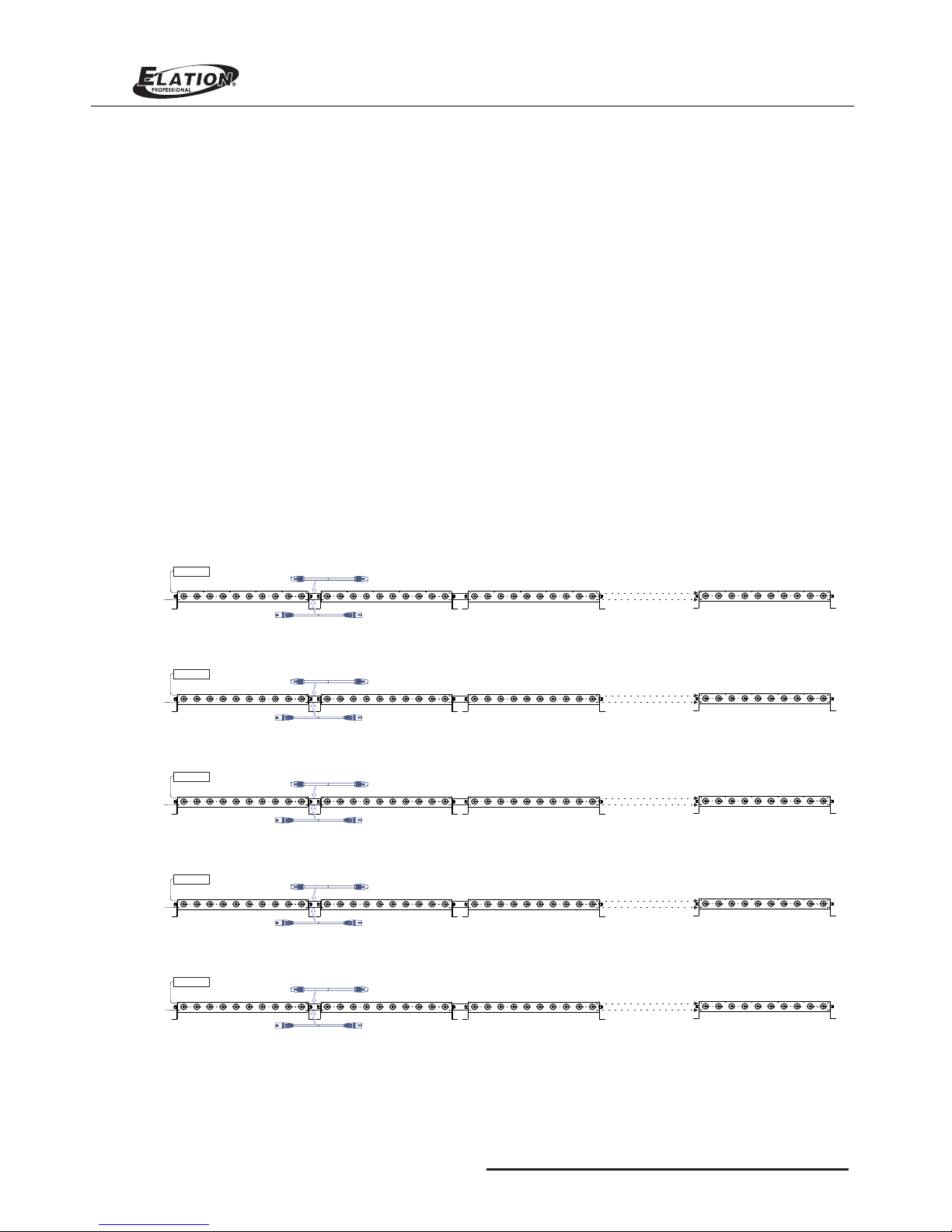
1=Ground
2=Data-
3=Data+
4,5=NC
1=Ground
2=Data-
3=Data+
4,5=NC
MODE MENU DISPLAY
DMX
Pro gr am
Add re ss
Cha nn el
No DM X
Gli de
Pro gr am
Spe ed
Mas te r
Lam p Mode
Fad e Time
001 - - 512
07 / 08 / 1 0 / 11 / 16
OFF / H old / Pro gram
OFF / O N
Ful l / 01-- 16 / Au to
01 -- 1 00
00 -- 1 00
Tung ste n / LED
00 -- 1 00
o
40 C
0.2m
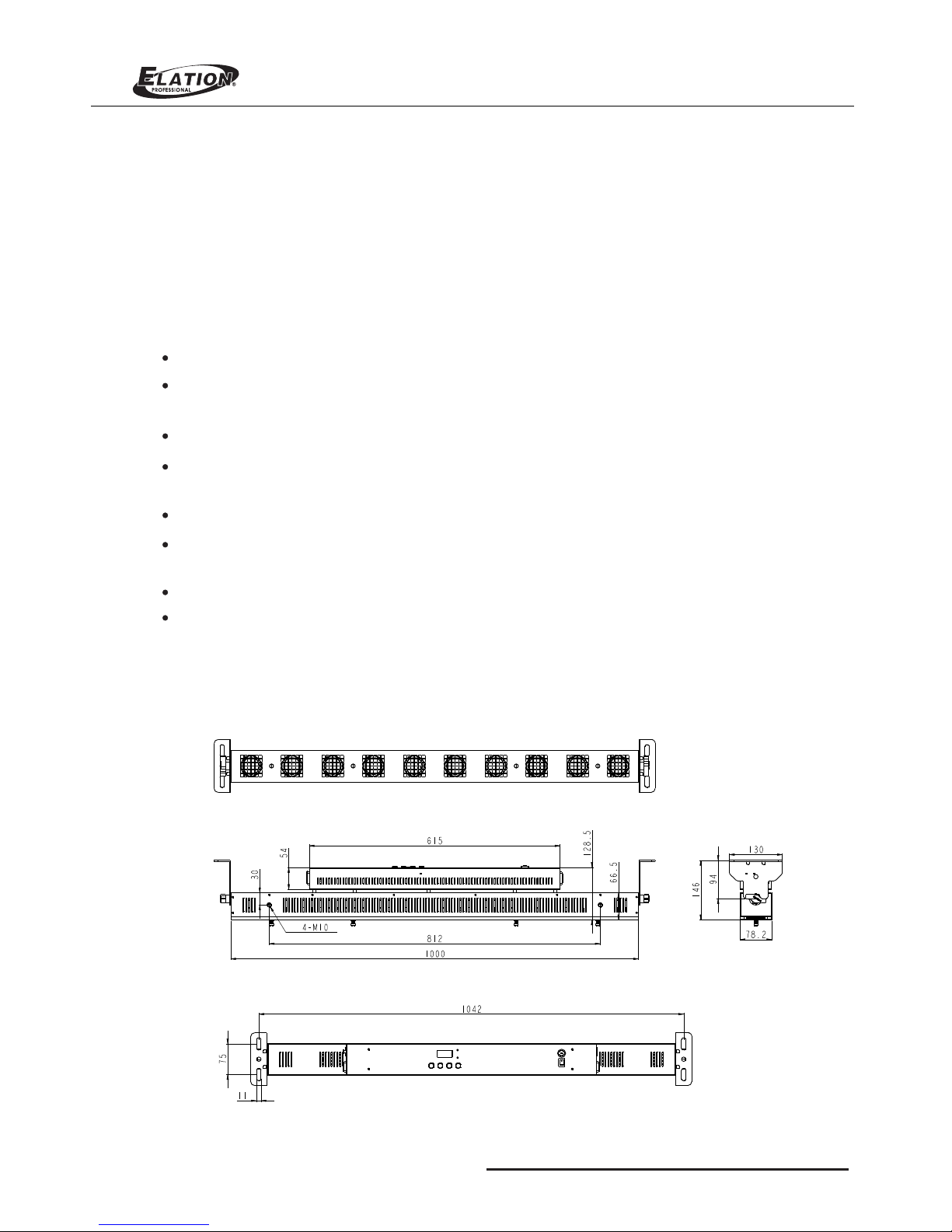
Lumina Strip
FOR S AFETY I NSTRU CTION AN D MOUNT ING OPT IONS RE FER TO USE R MANUA L
4
1
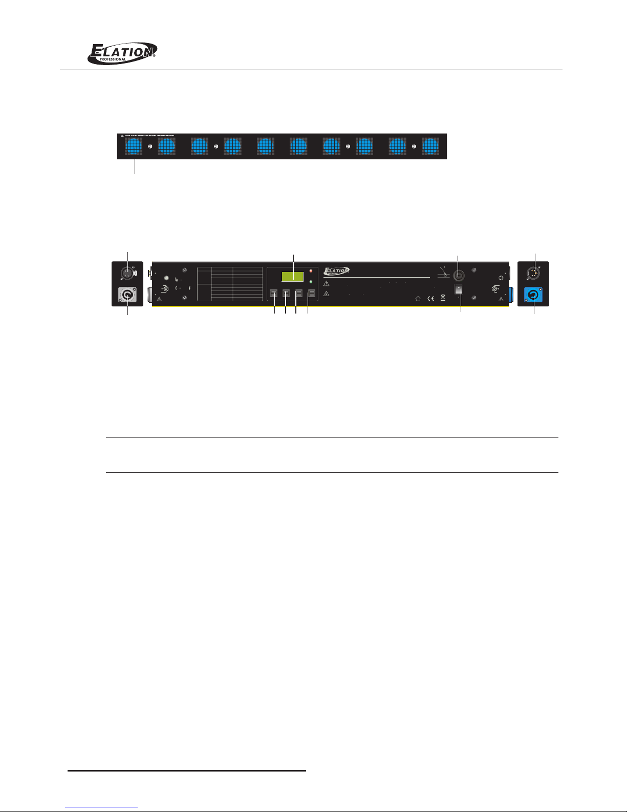
Layout Overview
1. Lamp: Totally 10 LEDs* Warm White, 7W
1. LCD Display
This multi-function display will detail all DMX Address, Chase , Program, Speed activity that pertains to the
current operation mode of the unit.
2. Mode button
This button will call up the unit operation mode between DMX and Chase mode.
3. Menu button
This button will active the different functions in Receive and Chase modes.
Front Panel Overview
Rear Panel Overview
6
8
2 3 4 5
7
9
101
11
Note: In the Chase mode, Menu key is used to only activate Chase Dimmer, Chase Program, Chase Speed,
Fade Time and Lamp Mode. While in the " Receive " mode, only used to only select DMX Address, Channel.
4. UP button
This button will increase the displayed value in the LED display.
5. Down Key
This button will decrease the displayed value in the LED display.
6. DMX Out
This connector sends your DMX signal through to the next unit.
7. DMX In
This connector accepts your DMX input signal.
8. Power Input:
AC100-240V~50/60Hz, Max15A. The supply power is input into your unit via this connector. Be sure to
always connect to proper voltage.
9. Power Thru:
AC100-240V~50/60Hz, Max15A. This connector sends the supply power to the next unit.
10. Fuse:
F3.15A 250V 5*20mm. These fuses prevent you from overloading damaging your unit. Be sure to always
replace with the exact same type fuse.
11. Power Switch:
Turn on/off the power supply.
Lumina Strip