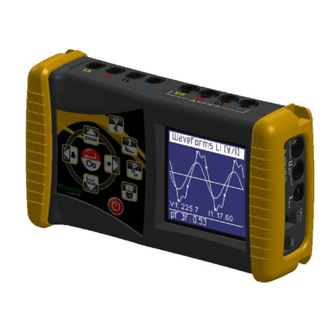
Elcontrol Microvip 3 plus User manual

ELCONTROL ENERGY NET SPA Via Vizzano 44 40044 Pontecchio Marconi (Bologna) - Italy -
Tel. 0039 051 6782006 Fax 0039 051 845544
MICROVIP3 Plus
PORTABLE ENERGY AND HARMONICS ANALYZER FOR
UNBALANCED 1 - AND 3 - PHASE SYSTEMS
USER MANUAL

I
MICROVIP3 PLUS MENU SHORT FORM
FUNCTION
MOVING ON
THE SAME
MENU LEVEL
PASSAGE TO A
LOWER MENU
LEVEL
EDITING
ESCAPE TO
AN UPPER
MENU LEVEL
PUSHBUTTONS
TO BE USED
PAGE
SEL + SET = SEL = select digit
SET = change digit
PAGE/ENTER
(for 3 sec.)
SET = change value
PAGE (3 sec.)
SEL

II
MICROVIP3 PLUS SET UP PAGES SHORT FORM
PAG
PAG PAG
SEL SEL
12 pages of three-phase measurements
7 pages of single-phase measurements Use SEL and
SET to select
baud rate (1200,
2400,4800,9600,
19200,38400),
* Note 1: these 3 pages are present only when LOG off. data bits (7/8),
stop bits (1/2),
parity (no/e/o).
PAG
PAG PAG PAG PAG PAG PAG PAG PAG PAG
SET SET SET SET SET
Use SEL and SET Use SET Use SEL
to select PT primary to select and SET
(from 1 to 999999 V) 1,2,5,10 to select
and PT secondary 15,20,30, from 1 to
(57.7,63.5,100,110,115, 60 minutes. SET 99 minutes
120,173,190,200,220 V), SET SET of data Press PAG
CT primary (from 1 to recording to clear
999999 A) and CT rate. internal
secondary (from 0.01 SET 00 = 3" memory;
to 1.00 V). SET SET display blinks
for 5"-10".
SET Std LOG = rms values
Sample LOG = V,I waveforms samples
Std1: kWh,kvarh SET Changing LOG type and confirming
Std2: kWh,kVAh by PAG., makes the display blinking
COG:
±
kWh,
±
kvarh for 5" -10".
Fundamental frequency
selection: 50 Hz or 60 Hz;
OFF = no harmonic
measurements and printouts.
Fnd = thd referred to the fundamental
instead of rms value.
SEt-UP MEAS
V
000100
P.t. 100
A
000005
C.t. 1.00
Std1
OPtion
m
Int 15
tiME
thd
50 Hz
*
Std
L
OG
* m
LOG 01
rAtE
*
LOG no
C
LEAr
k
COM 9.60
n 7 1
Std2
OPtion
COG4
OPtion
thd
O
FF
SAMPLE
LOG
LOG YES
CLEAr
StAr
inSErt
dELtA
inSErt
2 PH
inSErt thd
Fnd 50 Hz
thd
Fnd 60 Hz
thd
6
0Hz

III
INDEX
1 USER SAFETY......................................................................................................................................... 1
1.1 INTRODUCTION..................................................................................................................................... 1
1.2 SAFETY PRECAUTIONS ...................................................................................................................... 1
1.3 SYMBOLS................................................................................................................................................ 1
1.4 PRECAUTIONS IN CASE OF MALFUNCTIONING ...........................................................................1
2 INTRODUCTION TO THE MICROVIP3 PLUS ................................................................................... 2
2.1 MAIN FEATURES.................................................................................................................................. 2
2.2 GREAT VERSATILITY.......................................................................................................................... 2
2.3 PURPOSE AND USE.............................................................................................................................. 2
2.4 DESCRIPTION OF THE INSTRUMENT .............................................................................................. 3
2.5 HANDLING THE INSTRUMENT ........................................................................................................ 4
3 INSTALLATION..................................................................................................................................... 6
3.1 PRELIMINARY INSPECTION .............................................................................................................. 6
3.1.1 KIT CONTENTS ..................................................................................................................................... 6
3.2 SAFETY INSTRUCTIONS..................................................................................................................... 6
3.2.1 GROUNDING.......................................................................................................................................... 6
3.2.2 POWER REQUIREMENTS .................................................................................................................... 6
3.2.3 MAINS POWER FUSE ........................................................................................................................... 6
3.3 INSTRUMENT POWER......................................................................................................................... 7
3.3.1 MAINS POWER...................................................................................................................................... 7
3.3.2 BATTERY POWER................................................................................................................................. 7
3.4 MEASURING CONNECTIONS............................................................................................................. 8
3.4.1 VOLTMETER CONNECTIONS............................................................................................................. 8
3.4.2 CURRENT MEASURING CONNECTIONS.......................................................................................... 8
4 OPERATION ........................................................................................................................................... 9
4.1.1 MEASURING THREE PHASE POWER (STAR SYSTEM) ................................................................ 9
4.1.2 MEASURING THREE PHASE POWER (DELTA SYSTEM)............................................................... 10
4.1.3 MEASURING TWO PHASE POWER.................................................................................................... 10
4.2 MEASURING SINGLE PHASE POWER (PHASE-NEUTRAL)........................................................... 11
4.3 AC/DC MEASUREMENTS.................................................................................................................... 11
4.4 SPECIAL CONNECTIONS..................................................................................................................... 12
4.4.1 CTs AND NON STANDARD CLAMP METER GRIPS........................................................................ 12
4.4.2 THE INTA/1 AND INTA/5 INTERFACES ............................................................................................ 13
4.4.3 PTs............................................................................................................................................................ 14
5 MICROVIP3 PLUS OPERATING MODES ........................................................................................... 15
5.1 SINGLE PHASE MODE ......................................................................................................................... 15
5.1.1 THE PAGE KEY...................................................................................................................................... 15
5.1.2 ENERGY CONSUMPTION AND MAXIMUM DEMAND RESET ..................................................... 17
5.2 THREE PHASE MODE........................................................................................................................... 18
5.2.1 THE PAGE KEY...................................................................................................................................... 18
5.2.2 ENERGY CONSUMPTION AND MAXIMUM DEMAND RESET ..................................................... 21
5.2.3 THE SETUP PAGES MENU................................................................................................................... 22
5.3 PRINT FUNCTIONS............................................................................................................................... 24
5.3.1 MANUAL PRINTING............................................................................................................................. 24
5.3.2 TIMED PRINTING.................................................................................................................................. 26
5.4 THE CALENDAR CLOCK..................................................................................................................... 31
6 THE RS232C PORT ............................................................................................................................... 34
6.1 PC SOFTWARE...................................................................................................................................... 34
7 THE ON BOARD MEMORY................................................................................................................. 35
8 TECHNICAL SPECIFICATIONS.......................................................................................................... 35
8.1 GENERAL FEATURES............................................................................................................................ 35
8.2 OPERATING CONDITIONS AND TESTING......................................................................................... 36
8.3 POWER REQUIREMENTS...................................................................................................................... 36

IV
8.3 PRIMARY MEASUREMENTS ................................................................................................................ 37
8.4.1 PRIMARY MEASUREMENTS ACCURACY......................................................................................... 37
8.4.2 SECONDARY MEASUREMENTS ACCURACY................................................................................... 38
8.5 DISPLAYED (AND PRINTED) VALUES............................................................................................... 38
8.5.1 ADDITIONAL MEASUREMENTS OF THE PRINTER ......................................................................... 39
8.6 FORMULAE.............................................................................................................................................. 39
8.6.1 SINGLE-PHASE FORMULAE................................................................................................................. 39
8.6.2 THREE-PHASE FORMULAE .................................................................................................................. 40
8.6.3 HARMONIC FORMULAE ....................................................................................................................... 40
8.7 PRINTER SPECIFICATIONS................................................................................................................... 40
8.8 CLAMP METER SPECIFICATIONS....................................................................................................... 41
8.9 ON BOARD MEMORY SPECIFICATIONS............................................................................................ 41
9 OPERATION AND MAINTENANCE OF THE INSTRUMENT ............................................................ 41
9.1 CAUTIONS AND HINTS ......................................................................................................................... 41
ANNEX A
A.1 CHARACTERISTICS OF THE MICROVIP3 PLUS RS232C SERIAL
COMMUNICATION SOFTWARE PROTOCOL...................................................................................... 42
A.2 Q-BASIC EXAMPLE FOR MICROVIP3 PLUS READING .................................................................... 53
A.3 READING OF VOLTAGE AND CURRENT WAVEFORM SAMPLES................................................. 56
A.4 ON BOARD MEMORY DOWNLOADING.............................................................................................. 58

1
1USER SAFETY
−This instrument has been manufactured and tested to the standards laid down in IEC 1010-1 600V with regard to
category III installation and level of protection 2 under IEC 664-664A.
−It has left our factory in perfect working order.
−In order to maintain your instrument in perfect working order and to ensure safe operation, always follow the
instructions and notices given in this manual.
−Before connecting the instrument to the mains, check that the mains power and the instrument’s power requirements
correspond.
−Only connect the instrument to a grounded mains socket. Never use an extension lead without a ground wire.
−Plug in the main power plug before you switch on the measuring and control circuits.
Warning !
−Any breakage in the ground wire inside or outside the instrument, or the disconnection of the ground wire itself can
make the instrument dangerous to use. Do not interfere with the ground wire.
−During opening of covers or the removal of pieces, parts and connection points may also be live.
−Disconnect the instrument from the mains power source before starting any adjustment, maintenance, repair, or
replacement of components, and whenever the instrument has to be opened.
−Remember that capacitors inside the instrument may maintain their charge for a time even after the instrument has
been disconnected from the mains.
−Make sure that any replacement of safety devices are exactly the of right type and rated amperage. Never operate the
instrument with repaired safety devices or bypassed fuse holders.
−If it becomes clear that the instrument cannot be used in complete safety, remove it from service to prevent it being
used inadvertently.
−Safe operation cannot be guaranteed in the following cases :
−if the instrument is visibly damaged;
−if the instrument fails to operate correctly;
−if the instrument has been stored under unsuitable conditions for an extended period of time;
−if the instrument has been damaged during transit.
−Use only 80 mA T 250V fuses with 230VAC +/- 10% mains power.
−Use only 160 mA T 250V fuses with 110VAC +/- 10% mains power.
Read these pages carefully before installing
and using the instrument.
1.1 INTRODUCTION
The instrument described in this manual is intended for use by suitably trained personnel only.
Maintenance and repair operations involving the removal of the instrument cover must be carried out - exclusively - by
qualified and authorised staff.
1.2 SAFETY PRECAUTIONS
All personnel operating, servicing, or repairing the instrument must always follow standard safety procedures.
1.3 SYMBOLS
1.4 PRECAUTIONS IN CASE OF MALFUNCTIONING
If you have reason to believe that the instrument may not be functioning as it should, for example if it has been
damaged in transit or in operation, remove it from service and make sure that no other persons can use it inadvertently.
Consign it immediately to authorised personnel for checking and repair.
!READ THE USER MANUAL !

2
2 INTRODUCTION TO THE MICROVIP3 PLUS
2.1 MAIN FEATURES
The MICROVIP3 PLUS is a low cost, class 1 (IEC1036) high technology portable analyzer for both single phase and
three phase systems, manufactured by ELCONTROL ENERGY and supplied complete with three 1000A clip-on CTs,
voltage leads and all accessories in strong carry case.
The MICROVIP3 PLUS is capable of performing 189 true effective value measurements on an unbalanced three phase
system starting from three voltage and three current measurements: 33 parameters are displayed on its crisp high-
contrast back-lit LCD, 156 only on its built-in printer.
The instrument comes complete with a printer for manually controlled or automatic timed printout of all measurements,
as well as a calendar/clock for the display and printout of time and date.
The instrument can operate from 230 VAC Voltage supply (110VAC model is also available) or from internal
rechargeable batteries with an autonomy of over 7 hours provided no printing is performed and the display back-lit is
switched off.
A non-volatile flash 1 MB on-board memory provides data storage over extended survey periods including waveform
capture for current and voltage.
The MICROVIP3 PLUS is fitted with an RS232 port for connection to a Personal Computer for remote data control and
fast download via high-speed serial link.
The instrument has been designed for portable, mobile use in industrial environments.
2.2 GREAT VERSATILITY
The MICROVIP3 PLUS measures average three-phase and phase-neutral true rms voltage on all three phases, (max 600
Vrms), equivalent three phase current and true rms current per phase, total three phase power and power per phase, total
three-phase power factor and power factor per phase, reactive and apparent three phase system power, frequency, active
and reactive energy consumption/export, voltage and current total harmonic distortion per phase.
MICROVIP3 PLUS memorises energy consumption up to 999999 MWh and MVArh/MVAh and also memorises
active, reactive and apparent power peaks integrated using the technique of mobile averages over 1, 2, 5, 10, 15, 20, 30
or 60 minutes.
The basic model, supplied with three 1000A AC clamp meters, is capable of measuring power level from a minimum of
35W (5V, 7A) single phase to a maximum of 1,80MW (600V 1000A) three phase.
Optional AC clamp meters for up to 3000A and other DC models are also available.
All external CT/PT ratios, star/delta connection and power integration period are fully programmable.
The built-in 42 column graphic printer provides additional 156 parameters against manual print commands, and is
coupled to a calendar-clock to print out date and time along with measurements and to permit the generation of
automatically timed printed printouts at intervals of 1 to 99 minutes (with all measurements related to the printout start
time): data includes V & I harmonics to 24th multiple with both DC component and Displacement factor, and V & I
waveform/harmonic bar chart printout.
2.3 PURPOSE AND USE
The MICROVIP3 PLUS is intended for use by electrical power users who need to obtain an in-depth knowledge of their
plant and systems. It is also extremely useful for plant engineers, installers, maintenance engineers and electricians in
fault diagnosis and in the adjustment and repair of active electrical plant.
The MICROVIP3 PLUS enables you to:
−Control loads and consumption;
−Reduce overloads and power loss;
−Check on the correct sizing of new plant entering service;
−Prevent overheating and insulation problems;
−Solve power factor correction problems;
−Identify and eliminate load peaks and associated power problems;
−Check 400 Hz naval plants and 600 Hz aeronautical plant;
−Check uninterrupted power supplies with AC inputs and DC outputs;
−Measure asymmetrical signal for PWM controllers.

3
2.4 DESCRIPTION OF THE INSTRUMENT
The following components are located on the instrument’s front panel:
1: backlit liquid crystal display for read-out of measurements;
2: PAGE/SEL/SET keys for display and control of measurements;;
3: liquid crystal display for read out of calendar-clock;
4: PRG/SELC/SETC keys for control of calendar-clock;
5: PAPER key for manual paper feed;
6: PRINT key for manual printout of all measurements;
The following figure shows the layout of the above components.
Fig. 2.1
The following components are located on the rear panel:
1: mains power socket (for use with cable provided);
2: removable fuse-holder for safety fuse;
3: ON (I)/STANDBY (O) switch for activation of instrument;
4: RS232 port for connection to Personal Computer for remote data control, and fast download via high-speed
serial link;
5: single phase/three phase selector;
6: display backlight ON/OFF button (for use during battery operation to save power:
the backlight can be left on during mains operation).
The following figure shows the layout of the above components.
Fig. 2.2
1
4
DISPLAY
LIGHT
O
RS232C I
2
6
3
1 ø
3 ø FUSE
5
!
230V ±10%
50/60 Hz 4VA
80mA T 250V-
E
LCONTROL energy
MICROVIP3 PLUS 3-PHASE ENERGY & HARMONIC ANALYZER
PAGE
PRG SELC SETC
PRINT
PAPER
5
6
4
27
13
SEL
SET

4
The following components are located on the top of the instrument:
1: connectors compartment with voltage and current measurement connectors;
2: printer.
The following figure shows the layout of these components.
Fig. 2.3
2.5 HANDLING THE INSTRUMENT
Adjustable Handle: the handle can be adjusted as required to support the instrument at the angle for display
readability.
Shoulder Strap Hooks: The shoulder strap provided with the kit can be used for carrying the instrument. The handle
has special holes into which the shoulder strap hooks can be inserted.
Printer Access: to open the printer compartment, simply press lightly on the ribbed section of the printer cover as
shown.
1
2
Shoulder strap
anchorage points
Printer compartment
closed
Printer compartment
open

5
Replacing the printer cartridge: open the printer compartment and press down on the area marked PUSH to remove
the old cartridge. Fit the new cartridge and push gently down into position.
Replacing the printer roll: open the printer compartment and press down gently on the area marked PUSH to remove
the printer cartridge. Fit the paper toll and shown in the figure. Press the PAPER key repeatedly to feed the paper
through the mechanism. Replace the cartridge and check paper alignment.
Access to the volt and ampere measuring connectors: press on the ribbed area of the connectors compartment cover
on the top of the instrument (as for opening the printer compartment) and open it. The connector are located inside (see
figure). There are four single pole connectors for voltage measurements (N = neutral; L1 = R phase connection; L2 = S
phase connection; L3 = T phase connection) and 3 three pole connectors for the current measurement clamp meters (L1,
L2, L3).
PUSH
L
1 L2 L3 N L1 L2 L3
Press at ribbed areas Voltmeter and current
c
onnection compartment

6
3INSTALLATION
3.1 PRELIMINARY INSPECTION
When you receive your MICROVIP3 PLUS, check that the kit is complete and that the instrument has not been
damaged in transit.
Refer to ELCONTROL ENERGY service network for any repair or replacement.
3.1.1 KIT CONTENTS
The instrument comes in a practical impact resistant case and with a number of accessories. The complete kit should
comprise:
1 MICROVIP3 PLUS instrument case
1 MICROVIP3 PLUS
1 power cable
1 set of voltage measuring cables
3 1000A/1Vrms AC clamp meters with cables
2 5X20 T 80 mA fuse (230VAC ±10% power); T160 mA (110VAC±10% power)
1 spare printer ribbon cartridge
1 spare printer paper roll
1 shoulder strap
1 instruction manual
1 guarantee certificate
1 calibration certificate
check that the kit is complete before starting to install the instrument.
3.2 SAFETY INSTRUCTIONS
3.2.1 GROUNDING
The MICROVIP3 PLUS instrument can be powered from the mains using the cable provided or from the internal
battery. When using the instrument under mains power, always connect up the power cable before making in measuring
connections, and make sure that the mains cable is plugged in to a grounded power socket.
Only use extension mains cables with suitable ground connections.
Use the internal battery only for shorter periods of operation.
3.2.2 POWER REQUIREMENTS
The instrument can operate from mains power of 230VAC±10% 50/60 Hz (a special version is available for use with
110VAC±10% 50/60 Hz).
3.2.3 MAINS POWER FUSE
With 230 VAC±10% mains power only use 80 mA 250 V type T fuses of size 5X20.
With 110 VAC ±10%mains power only use 160 mA 250 V type T fuses of size 5X20.
Always disconnect the instrument from the mains before replacing a fuse.
To replace a fuse, simply unscrew the fuse holder on the rear panel.
Make sure that replacement fuses are of the same type and rating as the one removed.
Do not use the instrument with repaired or short-circuited fuses.

7
3.3 INSTRUMENT POWER
3.3.1 MAINS POWER
The kit includes a power cable for connection to the mains supply.
Make sure that mains power is 230VAC ±10% 50/60 Hz (or 110VAC ±10% 50/60 Hz if your version is designed for
this rating).
Simply plug the mains cable into the socket at the rear of the instrument (see Fig. 3.1) and into the mains power outlet.
Fig. 3.1
Set the I/O switch to I to switch the instrument on.
The I/O switch only affects the instrument’s low tension circuits and battery output circuits (practically speaking, with
the switch set to I, the instrument operates normally; with the switch set to O, the instrument control circuits are
switched off but the battery charging circuit remains on).
With the instrument switched on, you can make the measuring connections required.
3.3.2 BATTERY POWER
The MICROVIP3 PLUS can also work by its internal rechargeable battery. The instrument automatically switches to
battery power as soon as the mains cable is disconnected.
The MICROVIP3 PLUS uses a Ni-Cd 6V 940 mAh battery (with five 1,2 V 940 mAh elements in series) giving the
instrument an autonomy of over seven hours providing no printouts are required and the display backlight is switched
off (the display backlight can be activated by pushing the button on the rear panel, and switches off after approximately
15 seconds from the moment the button is released).
Do not use battery power for long measuring operations or when extensive printing is needed.
The instrument warns of low battery level by displaying three flashing dots on the calendar-clock display. When battery
power is low, the instrument automatically disables the print function (see figure).
To restore printer functions, connect the instrument to the mains power at least until the third dot goes out (15 minutes
approx.).
If the battery is completely drained, for example after a long period in storage, the instrument may not switch on at all.
If it happens, simply connect the instrument to the mains to recharge the battery.
Leave the instrument switched off (standby) and connected to the mains for 24 hours to fully charge the battery.
IMPORTANT: no ground connection is needed when the instrument is working by battery:
DO NOT CONNECT THE INSTRUMENT TO GROUND.
DISPLAY
LIGHT
O
RS232C I
1 ø
3 ø FUSE
!
230V ±10%
50/60 Hz 4VA
80mA T 250V-
PRG SELC SETC

8
3.4 MEASURING CONNECTIONS
The connectors for use in voltmeter and ammeter connections are located in the top of the instrument.
Follow these instructions carefully to avoid measurement errors.
3.4.1 VOLTMETER CONNECTIONS
Use the cables supplied for the purpose in the kit.
3.4.2 CURRENT MEASURING CONNECTIONS
Use the clamp meters supplied for the purpose in the kit.
When making current measurement make absolutely sure that each clamp meter is connected to the same phase
as the corresponding voltage measurement.
Incorrect connections can give rise to significant measuring errors since a phase angle between current and voltage of
120 degrees can be added.
When connecting the clamp meters with Std1 or Std2 option selected, you do not need to know the direction of flow
since the instrument automatically inverts in case of reversed connections.
The following diagram (fig. 3.2) shows the correct connection layout.
LOAD
N
(T) L3
(S) L2
(R) L1
Fig. 3.2
INPUT CURRENT
L
1 L2 L3 INPUT VOLTAGE
N L1 L2 L3
!
Connectors for
current measurements Connectors for
voltage measurements

9
4 OPERATION
4.1.1 MEASURING THREE PHASE POWER (STAR SYSTEM)
Set the connection type selector on the rear panel to 3 ø (THREE-PHASE) (see Fig. 4.1).
Fig. 4.1
Make all connections as shown Fig. 4.2.
LOAD
N
(T) L3
(S) L2
(R) L1
Fig. 4.2
If the neutral is unavailable it is possible to reconstruct it using the DSC-MT accessory (code 4AAC4) for voltages up
to 120VAC, DSC-400VAC (code 4AANY) for voltages up to 400VAC or DSCD2 (code 4AAHG) for voltages up to
700VAC. Make the necessary connections as shown in fig. 4.3.1
LOAD
DSC-MT
DSC-400VAC
DSCD2
(T) L3
(S) L2
(R) L1
Fig. 4.3.1
DISPLAY
LIGHT
O
RS232C I
1 ø
3 ø
FUSE
!
230V ±10%
50/60 Hz 4VA
80mA T 250V-

10
4.1.2 MEASURING THREE-PHASE POWER (DELTA SYSTEM)
(T) L3
(S) L2
(R) L1
Fig. 4.3.2
Connect L1, L2, L3; then connect the neutral voltage input to L3.
Note: Select Delta in Set-up Pages Menu
4.1.3 MEASURING TWO PHASE POWER
ACC
N
AC
Fig. 4.3.3
Connect L1 and L2; then connect the neutral Voltage input to L3.
Note : Select 2 PH in Set-up Pages Menu.

11
4.2 MEASURING SINGLE PHASE POWER (PHASE-NEUTRAL)
Set the connection type selector on the rear panel to 1ø (SINGLE-PHASE). Use only the instrument’s L1 phase inputs
(current to connector L1 and voltage between connectors L1 and N) as show in fig. 4.4.
LOAD
N
(R) L1
Fig. 4.4
4.3 AC / DC MEASUREMENTS
When taking measurements from DC circuits or networks, or circuits where alternating signals have direct components
superimposed (e.g. inverters, U.P.S., rectifiers), use the Hall effect clamp meters designed for these applications which
are available from the ELCONTROL ENERGY accessories catalogue. Use the ADAPTA-1V/1V adapter (code
4AACQ) for connections to the MICROVIP3 PLUS as shown in fig. 4.5 for the phase L1 inputs and in figs. 4.6 and 4.7
for three phase systems (taking care to ensure that voltage and current inputs correspond).
LOAD
ADAPTA-1V/1V
≅
LOAD
DSC-MT
DSC-400VAC
DSCD2
(
T) L3
(
S) L2
(
R) L1
ADAPTA-1V/1V
Fig. 4.5 Fig. 4.6
When either option Std1 or Std2 is selected, the clamp meters can be connected in either direction since the
MICROVIP3 PLUS automatically inverts current direction if necessary.

12
4.4 SPECIAL CONNECTIONS
4.4.1 CTS AND NON-STANDARD CLAMP METERS
When using current transformers or current measuring clamp meters other than those supplied, use adapter interfaces
INTA/1 (code 4AABB) and INTA/5 (code 4AABD), as listed in the ELCONTROL catalogue.
1) Connect the CT secondary to the INTA/1 or INTA/5 interface.
2) Remove the short circuit from the CT.
3) Connect the interface to the instrument taking care that the voltage and current inputs
correspond.
CAUTION: always use the correct connection layout to avoid serious damage to the instrument (see Fig. 4.7).
LOAD
(T) L3
(S) L2
(R) L1
INTA/1
INTA/5
N
LOAD
(T) L3
(S) L2
(R) L1
INTA/1
INTA/5
N
LOAD
(T) L3
(S) L2
(R) L1
INTA/1
INTA/5
N
Fig. 4.7
When your measuring is finished:
1) Disconnect the interface from the instrument
2) Short circuit the CT secondary
3) Disconnect the CT secondary from the INTA/1 or INTA/5 interface
Fig. 4.8 shows example of CT and non standard clamp meter connections.
Make sure that you program the values of the CT primary as instructed in chapter 5 below.
LOAD
(T) L3
(S) L2
(R) L1
INTA/1-INTA/5
N
Fig. 4.8

13
4.4.2 THE INTA/1 AND INTA/5 INTERFACES
Note: one of the CT terminals is normally connected to a common ground (see fig. 4.9).
When using the INTA/1 and INTA/5 interfaces, bear in mind that there is no galvanic separation so that the
instrument’s ground is actually connected directly to the plant.
You must therefore make sure that there are no spurious voltages between the plant ground and the instrument’s
grounds and that no other conditions which could cause damage to the instrument exist
In these cases, use an insulating transformer (fig. 4.10), or three SEPA 5X1 interfaces (code 4AAER) available in the
ELCONTROL ENERGY accessories catalogue.
L1
L2
L3
L1
L2
L3
Fig. 4.9
L1 TA (uscita 5A)
TA 5/1
INTA/1
LOAD
(
T) L3
(
S) L2
(
R) L1
SEPA 5X1
N
Fig. 4.10

14
4.4.3 PTs
Connection to 2 voltage transformers
with one phase of the secondary grounded
Connection to 3 star voltage transformer
(PTs)
T) L3
(S) L2
(R) L1
N
STAR
(T) L3
(S) L2
(R) L1
DELTA
Connection to 3 star voltage transformers with
one phase of the secondary grounded
L3
L2
L1
DELTA
N

15
5 MICROVIP3 PLUS OPERATING MODES
The MICROVIP3 PLUS displays measurements on its LCD.
A switch on the rear panel allows you to select one of two operating modes.
5.1 SINGLE PHASE MODE
The instrument display and data control functions are controlled by the keys on the front panel shown in fig. 2.1.
5.1.1 THE PAGE KEY
The PAGE key enables you to switch the display between seven measurement pages.
When you switch the instrument on in single phase mode, the first measurement page is displayed by default. Press the
PAGE key to move on to the next pages.
First page (single-phase)
Volt: Rms phase-to-neutral voltage
Amp: Rms current
Watt: Active power with full scale value of VxA.
CosΦP.F.: Power Factor with variations from -0,00 a +0,00.
Press page key to display
next pages
ELCONTROL energy
MICROVIP3 Plus 3-PHASE ENERGY & HARMONIC ANALYZER
PAGE
PRG SELC SETC
PRINT
PAPER
A
KW
CosΦ
P.F.
V
SEL
SET
Second page (single-phase)
kVAr: Reactive power.
kVA: Apparent power.
Hertz: voltage Frequency, range 20 to 600 Hz (AC) and 00 Hz (DC).
ELCONTROL energy
MICROVIP3 Plus 3-PHASE ENERGY & HARMONIC ANALYZER
PAGE
SEL PRG SELC SETC
PRINT
PAPER
KVA
Hz
VAr
SET
Third page (single-phase)
kvarh (kVAh) : Reactive energy consumption for the single-phase system
(Apparent energy with STD2 option)
kWh : Active energy consumption for the single-phase system
ELCONTROL energy
MICROVIP3 Plus 3-PHASE ENERGY & HARMONICS ANALYZER
PAGE
PRG SEL SET
PRINT
PAPER
KWh
kVArh
SEL
SET
Table of contents
Other Elcontrol Measuring Instrument manuals
