ELTRA CS-580A User manual

1
Manual
Carbon / Sulfur Analyzer CS‑580A (HELIOS)
REV0004 04/19
Translation

2
Copyright
© Copyright by
Eltra GmbH
Retsch-Allee 1-5
42781 Haan
Germany

3
Table of Contents
1Contact information .............................................................................................................................. 5
2Notes on the Manual ............................................................................................................................. 5
2.1 Explanations of the Safety Instructions ............................................................................................. 6
2.2 General Safety Instructions ............................................................................................................... 8
2.3 Intended use...................................................................................................................................... 9
2.4 Improper use...................................................................................................................................... 9
2.5 Explanation of signs and symbols ..................................................................................................... 9
3Packaging, Transport and Installation .............................................................................................. 10
3.1 Packaging........................................................................................................................................ 10
3.2 Transport.......................................................................................................................................... 11
3.3 Conditions for the Installation Site................................................................................................... 11
3.4 Type Plate Description..................................................................................................................... 12
4Pre-installation guide.......................................................................................................................... 13
5Installation............................................................................................................................................ 16
5.1 Setting check up .............................................................................................................................. 16
5.2 Front Panel Illustration..................................................................................................................... 18
5.3 Installation of Furnace Covers for Manual and Loader Setups....................................................... 20
5.3.1 Manual Setup............................................................................................................................... 20
5.3.2 Autoloader Setup......................................................................................................................... 21
5.4 Mains power Connections ............................................................................................................... 21
5.5 Data Interface .................................................................................................................................. 23
5.6 Oxygen Connection ......................................................................................................................... 24
5.7 Operation Modes ............................................................................................................................. 26
5.8 Adjusting the gas flow...................................................................................................................... 27
5.9 Temperature adjustment.................................................................................................................. 28
5.10 Preheating the furnace .................................................................................................................... 28
5.10.1 Configuration of preheating ..................................................................................................... 28
5.10.2 BIOS-configuration .................................................................................................................. 29
6Analysis................................................................................................................................................ 30
6.1 Working procedure .......................................................................................................................... 30
6.1.1 Procedure of carrying out analyses with autoloader, optional..................................................... 32
6.1.2 Procedure of carrying out analyses with manual loading of the sample ..................................... 33
6.2 TIC-determination (optional)............................................................................................................ 34
6.2.1 TIC-module.................................................................................................................................. 34
6.2.2 TIC analysis................................................................................................................................. 34
6.2.3 TIC-module installation................................................................................................................ 36
6.2.4 TIC-module Operation procedure................................................................................................ 37
6.3 Applications...................................................................................................................................... 38
6.3.1 Coal.............................................................................................................................................. 38
6.3.2 Calcium Carbonate...................................................................................................................... 38
6.3.3 Graphite....................................................................................................................................... 38
6.3.4 Limestone .................................................................................................................................... 39
6.3.5 Oil, Asphalt and Rubber............................................................................................................... 39
6.3.6 Wood............................................................................................................................................ 39
7Maintenance......................................................................................................................................... 40
7.1 General information ......................................................................................................................... 40
7.2 Cleaning........................................................................................................................................... 41
7.3 Reagent tubes filling ........................................................................................................................ 42
7.3.1 Reagent tube replacing................................................................................................................ 42
7.3.2 Filling quantities........................................................................................................................... 44
7.4 Moisture trap replacing (furnace)..................................................................................................... 47
7.5 O-rings replacement........................................................................................................................ 48

4
7.6 Dust filter cartridge replacing........................................................................................................... 49
7.7 Combustion tube replacement......................................................................................................... 50
7.8 Lance replacing ............................................................................................................................... 52
7.9 Heating elements replacing............................................................................................................. 53
8Function description........................................................................................................................... 55
8.1 Measuring principle.......................................................................................................................... 55
8.2 Gas flow system .............................................................................................................................. 56
8.3 Infrared cell...................................................................................................................................... 59
8.4 Micro-controller unit and PC Software............................................................................................. 60
9Ordering numbers............................................................................................................................... 61
9.1 Analyszer front view......................................................................................................................... 61
9.2 Rear side (outside view).................................................................................................................. 62
9.3 Bottom (outside view) ...................................................................................................................... 63
9.4 Left side (inside view) ...................................................................................................................... 64
9.5 Furnace side (inside view)............................................................................................................... 66
9.6 TIC-module...................................................................................................................................... 67
10 Disposal................................................................................................................................................ 69

5
1 Contact information
Please contact your local representative in the event of problems. You can find the complete
list of dealers at www.eltra.com.
Of course, you can also contact ELTRA-Germany directly:
ELTRA GmbH
Retsch Allee 1-5
42781 Haan
Germany
Web: www.eltra.com
Email: service@eltra.com
2 Notes on the Manual
This Operating Manual provides technical instructions for the safe operation of the device and
contains all necessary information about the topics given in the table of contents. This technical
documentation is meant to be a tutorial and a reference. The individual chapters are self-
contained.
Knowledge of the relevant chapters (for the respective target groups defined according to
areas) is a prerequisite for the safe and correct use of the device.
This Operating Manual contains no repair instructions. In the event of any faults or necessary
repair work, please contact your supplier or Eltra GmbH directly.
Amendments
Subject to technical changes.
Copyright
The forwarding or duplication of this documentation and the recycling and passing on of its
content are only permitted with the explicit consent of Eltra GmbH.
Any infringements of this constitute an obligation to pay damages.

6
2.1 Explanations of the Safety Instructions
In this Operating Manual we give you the following safety warnings
Mortal injury may result from not following these safety warnings. We give you the following
warnings and corresponding content.
DANGER
Type of danger / personal injury
Source of danger
–Possible consequences if the dangers are not observed.
•Instructions on how the dangers are to be avoided.
We also use the following signal word box in the text or in the instructions on action to be taken:
DANGER
Serious injury may result from not following these safety warnings. We give you the following
warnings and corresponding content.
WARNING
Type of danger / personal injury
Source of danger
–Possible consequences if the dangers are not observed.
•Instructions on how the dangers are to be avoided.
We also use the following signal word box in the text or in the instructions on action to be taken:
WARNING
Moderate or mild injury may result from not following these safety warnings. We give you the
following warnings and corresponding content.
CAUTION
Type of danger / personal injury
Source of danger
–Possible consequences if the dangers are not observed.
•Instructions on how the dangers are to be avoided.
We also use the following signal word box in the text or in the instructions on action to be taken:
CAUTION
In the event of possible property damage we inform you with the word “Instructions” and the
corresponding content.

7
NOTICE
Nature of the property damage
Source of property damage
–Possible consequences if the instructions are not observed.
•Instructions on how the dangers are to be avoided.
We also use the following signal word in the text or in the instructions on action to be taken:
NOTICE

8
2.2 General Safety Instructions
CAUTION
C1.0002
Read the manual
Non-observance of the operating instructions
−The non-observance of this manual can result in personal injuries.
•Read the manual before using the device.
•The adjacent symbol indicates the necessity of knowing the
contents of this manual.
Pos: 1.10 /0015 ELTR A/0099 Geräteneutr al/Standard Modu leEltr a/9926 Standard Mo dul Zielgrupp e@ 1 4\mod_1456483 021813_9.docx @ 9 9618@ @1
Target group:
All activities required for correct use are described in this Operating Manual. Any activities that
require opening of the enclosure and/or go beyond this may only be performed by authorized
electricians who have received in-depth training for this analyzer.
Pos: 1.11 /0015 ELTR A/0099 Geräteneutr al/Standard Modu leEltr a/9922 General Mod ul Sicherheitshin weise: Sie als Betreib er..... @ 12\mod_ 1443776927811_ 9.docx @ 89643 @ @ 1
As the operating company, you must ensure that the following applies to the persons working
on the analyzer;
•Operating personnel have been made aware of and have understood all safety
regulations;
•Operating personnel are familiar when starting work with all handling instructions and
regulations that apply to the relevant target group for them;
•Operating personnel have access at all times to the technical documentation of this
analyzer;
•New personnel are familiarized with the safe and intended use of the analyzer before
starting work on it by means of a verbal introduction by a competent person and using
this technical documentation.
Incorrect operation can result in serious injury and damage to property. You are responsible for
your own safety and for that of your employees.
Ensure that no unauthorized persons have access to the analyzer.
CAUTION
C2.0089
Changes to the machine
−Changes to the machine may lead to personal injury.
•Do not make any change to the analyzer.
•Use spare parts and accessories that have been approved by Eltra
GmbH exclusively.

9
2.3 Intended use
The analyzer was developed primarily for elemental analysis of organic samples (combustibles,
soils). Furthermore, an analysis of ores or building materials is possible under certain conditions.
Depending on the application, the sample weights, accelerator(s) and settings on the analyzer
can significantly influence the accuracy and precision of the measured values.
Therefore, use is permitted only in the laboratory by appropriately trained and instructed
personnel. All other applications are not permitted, especially in the private sector.
2.4 Improper use
Private use is not permitted. Repairs and modifications may only be carried out by Eltra GmbH,
or an authorized representative, or by qualified service technicians.
2.5 Explanation of signs and symbols
Number
Symbol
Reference
Meaning
12
Danger, high voltage, electric shock
13
IEC 60417-5041
Caution, hot surface
14
ISO 7000-0434B
General hazards –see documentation
-
BGV A8 W27
Risk of crushing

10
3 Packaging, Transport and Installation
3.1 Packaging
The packaging has been adapted to the mode of transport. It complies with the generally
applicable packaging guidelines.
Before packing, the analyzer must be wrapped in plastic foil to protect it from moisture and dust,
and then be placed in a wooden case. The wrapped analyzer should be surrounded by a layer
of plastic foam (or at least chips) of at least 10cm, in order to avoid any damage during
transport.
Especially the foam where the analyzer is put on is very important. It should neither be too hard
nor too soft. When the foam is too soft, the analyzer will practically touch the wood. Fix the foam
on the bottom of the wooden case by gluing.
The small loader (with 36 trays) can be packed in the wooden case together with the analyzer.
The bigger loaders (for 104 and 130 crucibles) however, are to be packed in separate carton
boxes and protected by foam or another shock absorbing material. The transportation of these
carton boxes has to be made on pallet.

11
The glass tubes must be empty.
3.2 Transport
NOTICE
N1.0075
Transport
−Mechanical or electronic components may be damaged.
•The device must not be bumped, shaken or thrown during transport.
•The device must be transported upright
3.3 Conditions for the Installation Site
Requirements regarding the operating conditions:
–For indoor use only.
–Operation up to max. 2,000 m above sea level.
–Ambient temperature of between 5°C and 40°C.
–Maximum relative air humidity < 80 % (at ambient temperatures ≤31°C), with linear
decrease up to 50% relative air humidity at 40°C, non-condensing.
–A residual current operated device (RCD, 30 mA).
–An exhaust system to evacuate the combustion gases is strongly recommended.
WARNING Provide an external fuse (20 ampere, B-type) and a residual current device when
connecting the mains lead to the mains in accordance with the regulations at the installation
site.
–Information about the required voltage and frequency of the device can be found on the
type plate .
–The data listed must be consistent with the existing power supply system.
–The device may only be connected to the power supply system using the connecting lead
supplied.
NOTICE
N2.0022
Electrical connection
Failure to heed the data on the type plate
−Electronic and mechanical components may be damaged.
•Only connect the device to a power supply system that is consistent
with the data on the type plate.
–Fluctuations of the mains supply voltage up to ± 10 %.
–The device must be operated in accordance with overvoltage category II and pollution
category 2, DIN EN 61010-1.
–Industrial environment in accordance with DIN EN 61010-1

12
3.4 Type Plate Description
NOTICE
N3.0022
Electrical connection
Failure to observe the values on the type plate
−Electronic and mechanical components may be damaged.
•Connect the device only to mains supply matching the values on the
type plate.
1
Device designation
2
Serial number
3
Year of manufacture
4
Voltage definition
5
Amps
6
Power
7
Manufacturer’s address
8
Item number
9
Mains frequency
10
Protection type
11
Disposal label
12
CE mark
Please quote the device designation (1), the serial number (2) of the device and the item
number (7) if you have any queries.

13
4 Pre-installation guide
DANGER
D1.0005
Mortal danger from electric shock
Exposed power contacts - High Voltage
−An electric shock can cause injuries in the form of burns and cardiac
arrhythmia, respiratory arrest or cardiac arrest.
•Set the mains switch of the analyser to position 0 and pull the
mains plug of the mains socket.
WARNING
W1.0021
Fire hazard / Risk of burns
Hot parts (crucibles, reagents,.. ) can fall down
−Ignition of tables, floors, or any other surface the hot part falls on
−Ignition of clothes and any other material
•Set up the analyser in a flame retardant environment. Pay special
attention to the table, the floor and any other surface being in the near
of the analyser
•Make sure that the surrounding space of the analyser stays clear of any
flammable material
•Always wear suitable clothing
•Keep the work environment clear of all materials that could catch fire
WARNING
Acceleration of fire / oxygen rich atmosphere
High purity oxygen carrier gas
–increased risk of fires
•Since the oxygen related risks heavily depend on the installation
situation in the laboratory, the user must make an own risk
assessment, evaluating the necessary steps to minimize the risks
introduced by handling oxygen from the source through the analyser
to the exhaust system.
Following requirements apply, when installing the analyzer:
Carrier gas Oxygen 99.95 % pure; 2 - 4bar (30 - 60psi)
Mains power supply 230VAC ±10%, 50/60Hz; 20A fuse
CEE-Plug 230V, 32A

14
Analyzer dimension 550 x 1000 x 600mm
Loader dimension 850 x 350 x 450mm (depending on version)
Analyser weight approx. 90kg
Loader weight approx. 55kg
–It is important to install the instrument on a stable place.
–The balance should rest on a vibration free support.
Loader dimensions:
Version 36p: 500x250x460mm
Version 130p: 900x500x460
Gas connections:
The supplied tubes carry a connector with G¼" inner diameter ".
Connections for compressed air:
The tubes supplied together with the analyzer, carry a connector with G¼" inner diameter.

15
Connections for the system exhaust:
WARNING
Toxic Fumes
The analyser combusts the customer samples, this might lead to toxic fumes
−Personal health issues may arise
•Depending on the customer samples it is highly advisable to connect
the system exhaust port to a lab ventilation system
The connection to the exhaust system (with and without connected hose) is on top of the
analyzer.

16
5 Installation
5.1 Setting check up
CAUTION
•V0092
Device falling down
Incorrect erection or inadequate working space
–Due to its weight, the device can cause injuries if it falls down.
•Only operate the device on a sufficiently large, strong, non-slip and
stable working area.
•Ensure that all feet of the device are standing securely.
WARNING
W2.0021
Fire hazard / Risk of burns
Hot parts (crucibles, reagents,..) can fall down
•Ignition of tables, floors, or any other surface the hot part falls on
•Ignition of clothes and any other material
•Set up the analyser in a flame-retardant environment. Pay special
attention to the table, the floor and any other surface being in the near
of the analyser
•Make sure that the surrounding space of the analyser stays clear of
any flammable material
•Always wear suitable clothing
•Keep the work environment clear of all materials that could catch fire
•Do not store any items on top of the analyzer
DANGER
D2.0005
Mortal danger from electric shock
Exposed power contacts - High Voltage
−An electric shock can cause injuries in the form of burns and cardiac
arrhythmia, respiratory arrest or cardiac arrest.
•Set the mains switch of the analyser to position 0 and pull the
mains plug of the mains socket.
NOTICE
Installation of the machine
–It must be possible to disconnet the machine from the mains at any time.
•Install the machine such that the connection for the mains cable is
easily accessible.
Since the analyser weighs about 90 kg it should be placed on a suitably stable and flame-
retardant surface. Due to the balance, the platform should be as free of vibration as possible.
The loader is attached to the right side of the analyser. The size of a desktop (approx. 200 cm
80 cm for the analyzer with 130-crucibles autoloader) is sufficient for the entire set-up.
Below is an example of installation:

17
The environment of the device does not have to necessarily be air-conditioned, although it is
best if the room temperature remains between 18°C and 30°C.
NOTICE
Under no conditions the device should be placed in direct sunshine!
Avoid places exposed to the wind of air conditioners or to the wind blowing through open
windows or doors.

18
5.2 Front Panel Illustration
CAUTION
C3.0081
Danger of bursting
−Defective reagent tubes may cause injuries in the form of cuts and other
personal injuries.
•Before installing the new reagent tubes, check if they are damaged.
•Wear protective gloves and safety glasses when installing/removing
the reagent tubes.
01
2
3
C/S-Analyser
Auto sampler
Air
Power
Inlet
Gas
Precleaning
Carrier
Moisture trap
HELIOS
80
20
12 0
Ai r 20 ° C 1 0 1 3 2 5 P a l/ h
20 0
50
30 0
Ai r 20 ° C 1 0 1 3 2 5 P a l/ h
20 0
10 0
50
30 0
Ai r 20 ° C 1 0 1 3 2 5 P a l/ h
Inlet
Lance
10 0
40
Filter
1
2
3
4
5
8
6
910
11
13

19
1
Moisture trap
2
Carrier gas purification
3
Mains power switch
4
Compressed air gauge
5
Oxygen pressure gauge
6
Furnace inlet flow adjustment
8
Furnace inlet flow meter
9
Carrier gas flow meter
10
Lance flow meter
11
Lance flow adjustment
12
Furnace low inlet
13
Dust filter cartridge

20
5.3 Installation of Furnace Covers for Manual and Loader Setups
WARNING
W3.0021
Fire hazard / Risk of burns
Hot parts (crucibles, reagents,...) can fall down
−Ignition of tables, floors, or any other surface the hot part falls on
−Ignition of clothes and any other material
•Set up the analyser in a flame retardant environment. Pay special
attention to the table, the floor and any other surface being in the near
of the analyzer
•Always wear suitable clothing
•Keep the work environment clear of all materials that could catch fire
•Install the needed covers as given in the following chapters
5.3.1 Manual Setup
If the Helios analyser was delivered without an autoloader system, it is configured to be used in manual
mode. In this case, please install the side cover plate (article number 35400-2003).
Other manuals for CS-580A
1
Table of contents
Other ELTRA Measuring Instrument manuals
ELTRA
ELTRA CSi/d User manual
ELTRA
ELTRA ON-900 User manual
ELTRA
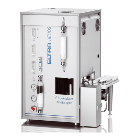
ELTRA CS-580A User manual
ELTRA
ELTRA CS-800 User manual
ELTRA
ELTRA ELEMENTRAC CS-i User manual

ELTRA
ELTRA ON-900 User manual

ELTRA
ELTRA CS-800 User manual
ELTRA
ELTRA Thermostep TGA User manual

ELTRA
ELTRA ELEMENTRAC ONHp2 User manual
ELTRA
ELTRA CS-2000 User manual
Popular Measuring Instrument manuals by other brands

Apogee Instruments
Apogee Instruments SP-420 owner's manual

Monroe Electronics
Monroe Electronics 257D Operator's manual

Kobold
Kobold DAG-M12 operating instructions

SMC Networks
SMC Networks ML2B Series operating manual
KROHNE
KROHNE DK32 Series Supplementary instructions

Vidicode
Vidicode Call Recorder Octo manual

