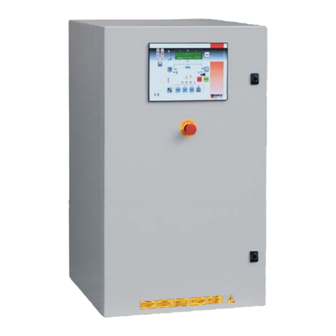
ELCOS QPE-C User manual

ENG
INSTALLATION, USE and MAINTENANCE Manual
QPE-C Elcos Polyvalent Panel
Command and control solutions
QPE-C-O-SC / QPE-C-O-CC / QPE-C-V
www.elcos.net
E-All. 47 proc.04 rev.03 del 10-01-2013

MANUAL CONTENTS:
•INSTALLATION
•USE
•MAINTENANCE
INDEX
USER MANUAL .................................................................................................. 5
1.1 INTRODUCTION ........................................................................................... 5
1.2 AIM .............................................................................................................. 5
1.3 OPERATING BASICS.................................................................................. 5
1.3.1 HOW THE QPE-C-V PANEL WORKS WITH THE GENSET ................................................5
1.3.2 QPE-C-VADJUSTABLE OPERATING MODES.....................................................................7
1.3.3 HOW THE QPE-C-O PANEL WORKS WITH THE GENSET................................................8
1.3.4 QPE-C-OCC OPERATING MODE.........................................................................................9
1.3.5 QPE-C-OSC OPERATING MODE.........................................................................................9
1.4 EXAMINATION OF “MC4 ON QPE-C PANEL” MODULE ............................. 11
1.5 FUNTIONAL DESCRIPTION OF PANEL COMPONENTS ............................ 11
1.5.1 DESCRIPTION OF KEYED SELECTOR FUNCTION .........................................................11
1.5.2 DESCRIPTION OF SINGLE BUTTONS AND WARNING LIGHT FUNCTIONS .................12
1.5.3 DESCRIPTION OF DIFFERENT MEASUREMENTS AND REPORTING PAGES .............14
1.6 COMMANDS AND FUNCTIONING IN THE THREE MODES ........................ 21
1.6.1 SETUP OF OPERATING MODES.......................................................................................21
1.6.2 MODE 1 MANUAL...............................................................................................................21
1.6.3 MODE 2 AUTOMATIC ........................................................................................................22
1.6.4 MODE 3 MOD – BUS...........................................................................................................22
1. SETUP LANGUAGE ................................................................................... 23
1.8 OTHER FUNCTIONS ................................................................................. 23
1.8.1 EMERGENCY STOP ............................................................................................................23
1.8.2 LOCKED GENSET................................................................................................................24
1.8.3 REMOTE TESTING - EJP.....................................................................................................24
1.8.4 MASTER START..................................................................................................................24
1.8.5 MAINTENANCE REQUEST..................................................................................................24
1.8.6 TELEPROCESSING .............................................................................................................24
1.8.7 SCHEDULED START-UPS...................................................................................................24
1.8.8 PROGRAMMABLE RELAY GENSET CONDITIONS...........................................................25
1.8.9 DIFFERENTIAL OR EARTH FAILURE PROTECTION......................................................25
1.8.10 ELECTRONIC OVERLOAD (51) AND SHORT-CIRCUITS (50) PROTECTION................25
1.8.11 REVERSE POWER PROTECTION (32) ............................................................................26
1.8.12 ALARMS HISTORY.............................................................................................................26
1.8.13 FUEL PUMP COMMAND....................................................................................................27
1.8.14 PROGRAMMING THE CARD THROUGH USB PORT......................................................27
1.8.15 PASSWORD LOCKED & UNLOCKING PROCEDURE .....................................................27
1.8.16 LED TEST ...........................................................................................................................27
1.8.17 AUTOMATIC BATTERY CHARGER FUNCTION................................................................27
1.8.18 FUEL THEFT FUNCTION....................................................................................................28
1.8.19 DUMMY LOAD FUNCTION .................................................................................................28
1.8.20 LOAD SHEDDING FUNCTION............................................................................................28
1.8.21 DOUBLE STARTER FUNCTION.........................................................................................28
1.8.22 FUEL MONITORING FUNCTION........................................................................................28
1.8.23 BATTERY CHARGED TEST FUNCTION............................................................................29
1.8.24 LOW R.P.M. OPERATING FUNCTION...............................................................................29
1.8.25 SERVICE PHONE NUMBER SIGNALLING ........................................................................29

Name file REV. File Date Rev. LANGUAGE
PAGE
QPE-C ENG version 01 13
03
01/01/2013 ENG
Page 3 of 102
1.8.26 VARIABLE SPEED FUNCTION........................................................................................... 29
1.9 INTERPRETATION OF ALARMS AND CONTROLS ..................................... 30
1.9.1 WHAT TO DO IN CASE OF GENSET FAILURE ................................................................. 30
1.9.2 ALARMS AND STATES SUMMARY..................................................................................... 34
1.9.3 ELECTRICAL MAINTENANCE............................................................................................. 35
1.9.4 MCCB RESET....................................................................................................................... 35
1.9.5 MECHANICAL MAINTENANCE ........................................................................................... 35
1.9.6 PERIODIC CHECKS............................................................................................................. 35
2.0 INSTALLATION MANUAL .......................................................................... 36
2.1 CONSTRUCTIVE DESCRIPTION OF QPE-C PANEL ................................... 36
2.1.1 EXTERNAL COMPOSITION QPE-C-V PANEL ................................................................... 36
2.1.2 QPE-C-OCC PANEL COMPOSITION (WITH SWITCHING ON BOARD) ........................... 37
2.1.3. QPE-C-SC PANEL COMPOSITION (WITHOUT SWITCHING)........................................... 38
2.2 CONSTRUCTIVE DESCRIPTION OF MC4 CARD ........................................ 40
2.2.2 CONSTRUCTIVE CHARACTERISTICS MC4 CARD.......................................................... 40
2.2.3 TECHNICAL CHARACTERISTICS SUMMARY................................................................... 41
2.3 ELECTRICAL CONNECTIONS BETWEEN MC4 MOTHERBOARD AND THE
GENERATING SET .......................................................................................... 42
2.3.1 J1 CONNECTOR POWER SUPPLY SYSTEMS C.C AND COMMAND RELAY.................. 42
2.3.2 J2 CONNECTOR CAN-BUS ENGINE CONNECTION......................................................... 43
2.3.3 J3 CONNECTOR ENGINE PROTECTION DIGITAL INPUTS............................................. 43
2.3.4 J4 CONNECTOR ANALOGICAL INPUTS TO MEASURE ENGINE PARAMETERS.......... 45
2.3.5 J5 CONNECTOR TOROID CONNECTION DIFFERENTIAL PROTECTION...................... 48
2.3.6 J7 CONNECTOR MCCB OPENING COIL ........................................................................... 50
2.3.7 J8 CONNECTOR LINE GENERATOR INPUT...................................................................... 50
2.3.8 J9 CONNECTOR FUEL PUMP SUPPLY............................................................................. 51
2.3.9 J10 CONNECTOR FLOATING OVERFLOW ....................................................................... 51
2.4 ELECTRIC WIRING MC4 MOTHERBOARD WITH EXTERNAL USERS ....... 52
2.4.1 J11 CONNECTOR DATA TRASMISSION IN MOD-BUS...................................................... 52
2.4.2 J12 CONNECTOR REMOTE CONTROLS .......................................................................... 52
2.4.3 J13 CONNECTOR REMOTE SIGNALS............................................................................... 52
2.4.4 J14 CONNECTOR PROGRAMMABLE REPORTING RELAY............................................. 53
2.4.5 J15 CONNECTOR MANAGEMENT OF MAINS-GENSET REMOTE SWITCHING ............ 53
2.4.6 J16 CONNECTOR BATTERY CHARGER CONNECTION.................................................. 55
2.4.5 J17 CONNECTOR MAINS PRESENCE SENSOR CONNECTION..................................... 56
2.5 SETUP ...................................................................................................... 5
2.5.1 SETUP MODE ACTIVATION................................................................................................ 57
2.5.2 CLOCK MENU ...................................................................................................................... 57
2.5.2 DIFFERENTIAL MENU......................................................................................................... 58
2.5.4 TIMES MENU........................................................................................................................ 59
2.5.5 THRESHOLDS MENU.......................................................................................................... 59
2.5.6 SETTINGS MENU................................................................................................................. 61
2.5.7 CALIBRATION MENU........................................................................................................... 64
2.5.8 MODEM MENU..................................................................................................................... 65
2.5.9 CAN-BUS MENU .................................................................................................................. 66
2.5.10 MOD-BUS MENU................................................................................................................ 67
2.5.11 USB MENU......................................................................................................................... 67
2.5.12 CARD MENU ....................................................................................................................... 68
2.5.13 SPECIAL FUNCTIONS MENU ........................................................................................... 70
2.6 TECHNICAL NOTES OF MC4 CARD .......................................................... 3
2.6.1 ENGINE RUNNING DETECTION.......................................................................................... 73
2.6.2 OPERATING WHEN THE MICROPRECESSOR IS BLOCKED........................................... 73
2.6.3 PASSWORD LOCK AND RELEASE..................................................................................... 73
2.6.4 PASSWORD RELEASE......................................................................................................... 74
2.6.2 FIRMWARE SOFTWARE DISPLAY...................................................................................... 74

Name file REV. File Date Rev. LANGUAGE
PAGE
QPE-C ENG version 01 13
03
01/01/2013 ENG
Page 4 of 102
2. ACCESSORIES COMBINABLE WITH QPE-C PANEL .................................. 6
2.7.1 MODEM FOR REMOTE MANAGEMENT OF GENERATING SET.......................................76
2.7.2 REMOTE DISPLAY...............................................................................................................78
2.7.3 AUX16 AUXILIARY 16-RELAY MODULE..............................................................................81
2.7.4 RADIO CHANNEL.................................................................................................................85
2.7.5 REMOTE MANAGEMENT SOFTWARE MC4 MONITORING .............................................85
2.7.6 MOD-BUS PROTOCOL........................................................................................................86
2.8 ELECTRIC CONNECTION DIAGRAM QPE-C ............................................. 90
2.8.1 ENGINE CONNECTOR QPE-C-V AND QPE-C-O...............................................................90
2.8.2 ALTERNATOR CONNECTOR FOR QPE-C-V.....................................................................90
2.8.3 FUEL TOPPING SYSTEM CONNECTOR QPE-C-V AND QPE-C-O...................................91
2.8.4 WIRING DIAGRAM FOR QPE-C-V.......................................................................................92
2.9 INSTALLATION ........................................................................................ 95
2.9.1 PROTECTION DEGREE........................................................................................................95
2.9.2 GROUND CONNECTIONS (PE)............................................................................................95
2.9.3 POWER CONNECTIONS......................................................................................................95
2.9.4 BATTERY CONNECTION.....................................................................................................96
2.9.5 SUMMARY OF CONTROL PROBES MOUNTED ON THE ENGINE ..................................96
2.9.8 DIELECTRIC STRENGTH TEST...........................................................................................97
2.10 SERVICE PROCEDURES ........................................................................ 98
2.10.1 FIRST START-UP PROCEDURE........................................................................................98
2.10.2 PROCEDURE FOR REPLACING THE BATTERY..............................................................98
2.10.3 PROCEDURE FOR REPLACING MC4 CARD....................................................................98
3.0 MAINTENANCE MANUAL ......................................................................... 99
3.1 ROUTINE MAINTENANCE.......................................................................................................99
3.2 ELECTRICAL AND MECHANICAL MAINTENANCE................................................................99
3.3 TEST AND ALARMS SIMULATION..........................................................................................99
3.3 ENGINE PROTECTIONS..........................................................................................................99
3.4 GENERATOR PROTECTION...................................................................................................99
3.5 51 OVERLOAD PROTECTION................................................................................................99
3.6 TROUBLESHOOTING ............................................................................................................100
WARRANTY ................................................................................................... 101
This document is the exclusive property of Elcos S.r.l. and it reserves all rights in this document and in the information
contained therein.
Elcos S.r.l. reserves the right to update and modify this document at any time and without any advance notice.
Reproduction, use or disclosure to third parties without express authority is strictly forbidden.

Name file REV. File Date Rev. LANGUAGE
PAGE
QPE-C ENG version 01 13
03
01/01/2013 ENG
Page 5 of 102
The data presented herein could undergo modifications for technical improvements without any notice.
USER MANUAL
1.1 INTRODUCTION
Congratulations for choosing QPE-C panel (with MC4 electronic logic) for managing your genset.
Later on, you will appreciate the great flexibility of use and high performance allowed by the high technology
of the electronic module MC4.
This is a microprocessor based electronic module that manages all types of gensets, both traditional ones
and with CAN-BUS commands. It is set to communicate over MOD-BUS with various devices such as main-
genset transfer switching cabinets with switching, pc, remote touch-screen panels, alarm repeating modules
etc.
Through a GSM module (integrated on-demand) you can manage and totally control your genset from miles
away.
MC4 is equipped with fully digital instrumentation that allows you to monitor all the parameters of the engine,
generator, and related accessories.
The USER MANUAL aims to provide a clear and simple guide in order to consent a quick, complete and
safe use of the genset.
1.2 AIM
This manual provides all the necessary information regarding the use of the genset with QPE-C panel, both
in vertical QPE-C-V and in horizontal version QPE-C-O:
1. Knowing the operating basics of the panel;
2. Interpreting the indications of the electronic panel;
3. Setting the electronic card in the different service requirements;
4. Making the minimum necessary checks to ensure the smooth functioning of the genset.
Any technical or adjustment elements are not discussed because they are managed by the manufacturer
during creation of the machine.
1.3 OPERATING BASICS
The types of QPE-C panels differ in type of construction, based on the powers of use and the presence or
absence of the integrated switching between Mains-Gen Set:
- QPE-C-V vertical arrangement for Gen Sets from 110kVA to 2.500kVA,
- QPE-C-OSC horizontal arrangement without switching for Gen Sets from 7kVA to 100kVA,
- QPE-C-OCC horizontal arrangement with switching on board for Gen Sets from 7kVA to 100kVA.
1.3.1 HOW THE QPE-C-V PANEL WORKS WITH THE GENSET
The QPE-C panel can be matched with all the generators with power range from 10 to 2500 KVA, with
operating voltages from 220 to 460 volts, 50 or 60Hz, with traditional engines or with Can-bus control ones.
In Fig. 1 is shown the standard components of the plant that is made of:
a generating set GE, control panel QPE-C-V, a machine switch INT. (which varies according to the power of
the genset).

Name file REV. File Date Rev. LANGUAGE
PAGE
QPE-C ENG version 01 13
03
01/01/2013 ENG
Page 6 of 102
The QPE-C panel monitors and detects all the parameters of both the engine and the generator. It has a
three-position key that sets the type of plant’s operating mode.
With key on position 0 the panel is switched off, the genset is off.
With key on Manual the start-up is decided by the user by pressing the start button.
With key on Automatic, depending on the operating mode, the start-up could be through external contact,
lack of electricity from the relative mains, command in MOD-BUS, from the communication network via sms,
etc..
During the functioning all the electrical and mechanical parameters of the genset are displayed and all the
protections are enabled, including overload, short-circuit and earth fault if set.
If an anomaly happens the INT switch opens through the opening coil and it disconnects the load, then after
the cooling phase the engine stops.
In combination with an ATS (Automatic Transfer Switch) with or without mains sensor, it becomes a
complete system for the mains failure, (as per Figure 2). The QPE-C panel is even able to autonomously
manage the switching mains-genset.
Fig.2
RETE
Public mains
QPE
-
C
Command and control panel
CR
Mains counter
GE
Generating set
CARICO
Preferential load
CG
Genset counter
Fig. 1

Name file REV. File Date Rev. LANGUAGE
PAGE
QPE-C ENG version 01 13
03
01/01/2013 ENG
Page 7 of 102
(generator + engine)
1.3.2 QPE-C-VADJUSTABLE OPERATING MODES
The QPE-C panel, in order to cover all needs, can be set in three distinct operating modes:
1 Manual mode “MOD 1” (start-up command from external potential free contact)
2 Automatic mode “MOD 2” (start-up command from internal mains sensor)
3 Mod-bus mode “MOD 3” (start-up command from remote mod-bus)
The setting of these three modes is done by inserting three micro-switches (dip 1-2-3) on the
motherboard, see page 30.
MANUAL MODE (MODE 1)
In Manual mode, the panel can be used in two ways, depending on the position of the board key.
With key on Manual, the genset start-up occurs exclusively by pressing the "start" button by the user.
With key on Automatic, the start-up occurs through an external command (potential free contact) that if
Active, it launches the automatic process of start-up and the possible management of inserting load.
So, the consent of start-up can be given by external devices such as floats, pressure switches,
thermostats, relay voltmeters etc.
AUTOMATIC MODE (MODE 2)
With key on Manual, the genset start-up occurs exclusively by pressing the "start" button by the user.
With key on Automatic, the panel is able to operate as an emergency system to the mains. It fully
manages both the start-up of the genset and the complete management of mains-genset switching in the
separated ATS.
Suppose that we are in the situation represented in Figure 2, where the mains is within normal values:
the CR counter is closed and the use is powered by the mains.
The QPE-C monitors the mains and in case of any anomaly or the lowering or lack of a phase or
because of asymmetry of the phases themselves, it acts as follows:
1. It commands the opening of CR mains counter;
2. It enables the start-up of the genset and once it has reached the right functioning level, it commands the
closing of the CG counter, powering the use through the GE generator;
N.B.: During the functioning, the engine and generator are monitored to determine if any abnormalities
occur. If this is the case, these abnormalities would cause the immediate arrest of the genset with
consequent storage and visualization onto the display, showing the cause of the alarm (e.g. low oil
pressure, overload, etc.).
3. When the mains come back to normal values, after a set delay the QPE-C opens the CG genset
counter and after one second, closes the CR counter. In this way it re-powers the use with the mains.
4. The genset keeps running for at least one minute to burn off the excessive heat and at the end of cooling
time, it stops automatically.
If the user has his own ATS with an independent management of switching, then he can only use the
mains sensor of QPE-C panel to handle only the start-up when the mains fail.
MOD-BUS MODE (MODE 3)
In Manual mode, the panel can be used in two ways, depending on the position of the board key.
With key on Manual, the genset start-up occurs exclusively by pressing the "start" button by the user.
With key on Automatic, the start input can be sent through a Mod-Bus message, which is sent by a
management control unit or by an external PLC.
The start-up input may be given from external devices such as PLCs, remote management systems,
etc..

Name file REV. File Date Rev. LANGUAGE
PAGE
QPE-C ENG version 01 13
03
01/01/2013 ENG
Page 8 of 102
1.3.3 HOW THE QPE-C-O PANEL WORKS WITH THE GENSET
The QPE-C-O panel can be matched with all the generators with power range from 4 to 100 kVA, with
operating voltages from 220 to 460 volts, 50 or 60Hz, with single or three-phase system.
The following two executions are available:
1. QPE-C-OCC (fig 1) panel with internal mains-genset switching by mechanically and electrically
interlocked contactors.
2. QPE-C-OSC (fig. 2) panel without mains-genset switching and equipped with a 63A switch
complete with opening coil for units up to 40 kVA, and a 160A switch for units up to 100 kVA.
Fig.2
The QPE-C-O panel monitors and detects all the parameters of both the engine and the generator. It has
a three-position key that sets the type of plant’s operating mode.
With key on position 0 the panel is switched off, the genset is off.
With key on Manual the start-up is decided by the user by pressing the start button.
With key on Automatic, depending on the operating mode, the start-up could be through external
contact, lack of electricity from the relative mains, command in MOD-BUS, from the communication
network via sms, etc..
During the functioning all the electrical and mechanical parameters of the genset are displayed and all
the protections are enabled, including overload, short-circuit and earth fault if set
If an anomaly happens the switch (QPE-C-OSC) opens or the genset contactor (QPE-C-OCC) and it
disconnects the load, then after the cooling phase the engine stops.
Fig. 1

Name file REV. File Date Rev. LANGUAGE
PAGE
QPE-C ENG version 01 13
03
01/01/2013 ENG
Page 9 of 102
1.3.4 QPE-C-OCC OPERATING MODE
The QPE-C-OCC panel, (with switching) is complete with a 4P mains-genset switching system realized
through mechanically and electrically interlocked contactors.
The installation is very easy and it exclusively needs the main power line connection with the load inside
the genset.
MANUAL MODE.
With key on manual, the genset start-up is only made by pressing the "start" button by the operator. If the
public mains is present, then the load remains supplied from the mains. In case of power failure, the
generating set provides power to feed the load instantly.
AUTOMATIC MODE.
With key on Automatic, the panel is able to operate as an emergency system to the mains. It fully
manages both the start-up of the genset and the complete management of mains-genset switching.
Suppose that we are in the situation represented in Figure 1, where the mains is within normal values:
the CR counter inside the panel is closed and the user is powered by the mains.
The QPE-C-OCC monitors the mains and in case of any anomaly or the lowering or lack of a phase or
because of asymmetry of the phases themselves, it acts as follows:
1. It commands the opening of CR mains counter;
2. It enables the start-up of the genset and once it has reached the right functioning level, it commands
the closing of the CG counter, powering the user through the GE generator;
N.B.: During the functioning, the engine and generator are monitored to determine if any abnormalities
occur. If this is the case, these abnormalities would cause the immediate arrest of the genset with
consequent storage and visualization onto the display, showing the cause of the alarm (e.g. low oil
pressure, overload, etc.).
3. When the MAINS come back to normal values, after a set delay the QPE-C-OCC opens the CG
genset counter and after one second, closes the CR counter. In this way it re-powers the use with
the mains.
4. The genset keeps running for at least one minute to burn off the excessive heat and at the end of
cooling time, it stops automatically.
The switching contained in the QPE-C-OCC panel is capable of switching line currents up to max 60A for
panels with power up to 40 kVA and 160A for panels up to 100 kVA.
1.3.5 QPE-C-OSC OPERATING MODE
The QPE-C-OSC panel, in order to cover all needs, can be set in three distinct operating modes:
1 Manual mode “MOD 1” (start-up command from external potential free contact)
2 Automatic mode “MOD 2” (start-up command from internal mains sensor)
3 Mod-bus mode “MOD 3” (start-up command from remote mod-bus)
The setting of these three modes is done by inserting three micro-switches (dip 1-2-3) on the
motherboard, see paragraph 1.6.1.
MANUAL MODE (MODE 1).
In Manual mode, the panel can be used in two ways, depending on the position of the board key.
With key on Manual, the genset start-up occurs exclusively by pressing the “start” button by the operator.
With key on Automatic, the start-up occurs through an external command (potential free contact) that if
Active, it launches the automatic process of start-up and the possible management of inserting load.

Name file REV. File Date Rev. LANGUAGE
PAGE
QPE-C ENG version 01 13
03
01/01/2013 ENG
Page 10 of 102
So, the consent of start-up can be given by external devices such as floats, pressure switches,
thermostats, relay voltmeters etc.
AUTOMATIC MODE (MODE 2).
With key on Manual, the genset start-up occurs exclusively by pressing the “start” button by the operator.
With key on Automatic, the panel is able to operate as an emergency system to the mains. It fully
manages both the start-up of the genset and the complete management of mains-genset switching in the
separated ATS.
Suppose that we are in the situation represented in Figure 2, where the mains is within normal values:
the CR counter is closed and the use is powered by the mains.
The QPE-C monitors the mains and in case of any anomaly or the lowering or lack of a phase or
because of asymmetry of the phases themselves, it acts as follows:
1. It commands the opening of CR mains counter;
2. It enables the start-up of the genset and once it has reached the right functioning level, it commands
the closing of the CG counter, powering the use through the GE generator;
N.B.: During the functioning, the engine and generator are monitored to determine if any abnormalities
occur. If this is the case, these abnormalities would cause the immediate arrest of the genset with
consequent storage and visualization onto the display, showing the cause of the alarm (e.g. low oil
pressure, overload, etc.).
3. When the mains come back to normal values, after a set delay the QPE-C-OSC opens the CG
genset counter and after one second, closes the CR counter. In this way it re-powers the use with
the mains.
4. The genset keeps running for at least one minute to burn off the excessive heat and at the end of
cooling time, it stops automatically.
If the user has his own ATS with an independent management of switching, then he can only use the
mains sensor of QPE-C-OSC panel to handle only the start-up when the mains fail.
MOD-BUS MODE (MODE 3).
In manual mode the panel can be used in two ways, depending on the position of the key on board.
With key positioned to manual, the genset start-up is only made by pressing the "start" button by the
operator.
With key positioned to automatic, the start-up is made through an external command, sent on the MOD-
BUS line that, if active, starts the automatic start-up process and possible management of inserting load.
So, the start input can be sent from external devices, such as teleprocessing systems, PLCs, etc..

Name file REV. File Date Rev. LANGUAGE
PAGE
QPE-C ENG version 01 13
03
01/01/2013 ENG
Page 11 of 102
1.4 EXAMINATION OF “MC4 ON QPE-C PANEL”
MODULE
Functional description of panel controls.
1.5 FUNTIONAL DESCRIPTION OF PANEL COMPONENTS
1.5.1 DESCRIPTION OF KEYED SELECTOR FUNCTION
1. The keyed selector selects the operating mode. With key on AUT position,
the genset starts automatically. According to the functional mode that is
set, the command can be made via external potential free contact, via the
mains failure, via a Mod-Bus signal, or through an sms etc.
With key on automatic, the green led corresponding to the writing
remains turned on with fixed light.
1. COMMAND KEY
Automatic functioning. (AUT)
Manual functioning. (MAN)
4.
RESET / ENTER buttons to restore
functions or unlock alarm. In Setup mode,
it confirms the set data (T4).
5.
CK MUTE alarm
Fuel pump manual command
Engine pre-heater or glow-plug (T1 - T2 - T3)
2.
Buttons for manual command of
running or arrest. (T7 - T8)
3.
Graphic display for visualizing all the
measurements, alarms and commands.
6
. Button for activating the
automatic weekly test and
instantaneous test (T9).
7.
Buttons to change the display view or
to modify parameters in Setup. (T5 - T6)

Name file REV. File Date Rev. LANGUAGE
PAGE
QPE-C ENG version 01 13
03
01/01/2013 ENG
Page 12 of 102
2. With the keyed selector on ZERO, the genset is totally disabled, power consumptions on the power
battery are excluded. If the key is turned to ZERO position while the genset is running, the panel will
not switch off immediately, but it will first start the process of shutdown and when the engine cooling
process is finished, the panel will shut down entirely. The timing of the shutdown procedure is
displayed through an animated hourglass on the graphic display.
3. When the key is on MAN, the START and STOP buttons are enabled. Therefore, it is up to the user
to decide the start-up of the genset.
1.5.2 DESCRIPTION OF SINGLE BUTTONS AND WARNING LIGHT FUNCTIONS
1. SIREN MUTE BUTTON (T1)
When it is pressed, this button silences the alarm buzzer, the corresponding
red LED indicates the presence of a failure. The reset of the alarm occurs by
pressing the reset button indicated here below. In Setup mode, pressing the
button allows you to leave the various Setup menu.
2. FUEL PUMP ACTIVATION BUTTON (T2)
If it is pressed with key on Manual, it activates the pump for refuelling the daily
tank from an external tank, if it is pressed again, it switches it off. The pump
stops automatically when it reaches the maximum level. The corresponding
green LED lights up every time the pump starts running.
With key on Automatic, the button is disabled because the activation of the fuel
pump takes place automatically according to the level of the tank.
In setup mode, the pressure of the button needs to increase the values of the parameters visualized on
the display.
3 GLOWPLUGS OR ENGINE PRE-HEATER ACTIVATION BUTTON (T3)
The warning light corresponding with this button has two distinct functions,
depending on the type of setting. If the “glow-plugs” function is enabled in the
card, the light will turn on before the start-up, indicating the insertion of glow-
plugs for pre-scheduled time.
If the “engine pre-heater” function is enabled on the card, the light turns on
every time the resistance that keeps the engine water at the correct
temperature is activated. The button is active only in manual mode and only in "glow-plugs" mode. If
pressed, it allows the reintegration of glow-plugs.
In Setup mode, the pressure of the button needs to decrease the values of the parameters visualized on
the display.
4 RESET-ENTER BUTTON (T4)
If pressed during normal functioning, it erases the alarms states and restores
the functions. In setup mode, it confirms the selection or stores the data.
5 STOP BUTTON (T7)
This button is always enabled both in manual and automatic. It stops the
machine when pressed. The red LED corresponding with this button indicates
that the shutdown phase is in progress.

Name file REV. File Date Rev. LANGUAGE
PAGE
QPE-C ENG version 01 13
03
01/01/2013 ENG
Page 13 of 102
6 START BUTTON (T8)
This button in enabled only when the change-over switch is on MAN position.
The control is manual, it is therefore necessary to hold the start button until the
start-up is completed. The green LED corresponding with this button indicates
that the start-up command is in progress. With key turned to automatic
position, if the Start Button is pressed for more than 5 seconds, it activates the
automatic battery test by running the starter motor without starting the engine.
7 GENSET TEST BUTTON (T9)
The button in active only if the key is on Automatic and it enables two
different functions:
“Instantaneous automatic test” is obtained by pressing the button for more
than 3 seconds. The genset starts, the machine runs freely for the scheduled
time and then it stops automatically. The corresponding green led flashes,
indicating that it has activated the function.
“Programmed automatic test” is activated by quickly pressing the button. This function allows the inner
timer to activate, in order to test the genset at pre-scheduled times and dates.
If this function is activated, the corresponding green LED remains turned on with fixed light.
The setup test scheduling is carried out in Setup menu described later, see page 47.
8 DISPLAY MODE BUTTONS (T5-T6)
These buttons allow you to navigate around the display pages. In setup
mode, they allow you to access the different menus.

Name file REV. File Date Rev. LANGUAGE
PAGE
QPE-C ENG version 01 13
03
01/01/2013 ENG
Page 14 of 102
1.5.3 DESCRIPTION OF DIFFERENT MEASUREMENTS AND REPORTING PAGES
During the ignition phase, for a few seconds, the screen displays the company logo and the version of the relay card
software. Then the first page display appears:
Page 1
The first page shows the user the main functioning indications of the genset.
In detail, these are as follows:
1. Key state display, possible indications AUT. (key on automatic), MAN (key on manual), MSTR (forced
start-up with key on off, Master start function).
2. Voltage supplied by the generator, the parameter changes sequentially according to the phases
indicated by point 12.
3. Current supplied by the machine on phase X.
4. Operating frequency.
5. Engine alarm display, in case of multiple alarms they are displayed alternatively.
6. Page number
7. Generator status, possible combinations, G-ALRM (genset in alarm), G-off (genset turned off), G-on
(genset running), G-stop (genset shutting down), G-strt (genset starting up).
8. Indication of operating mode MOD1 (manual operating), MOD2 (automatic operating) MOD3 (mod-bus
operating).
9. Time Display
10.Date display
11.Display numbers of alarms occurring simultaneously.
12.Sequential display of voltage measurements.
13.This icon indicates the presence of a modem, of a GSM signal and, if flashing, the presence of sending
and receiving an SMS.
14.Presence of scheduled events of genset start-up on a pre-set timetable.
15.Animated icon to display timing in progress.
1
2
3
4
5
6
8
16
7910
151413
12
11

Name file REV. File Date Rev. LANGUAGE
PAGE
QPE-C ENG version 01 13
03
01/01/2013 ENG
Page 15 of 102
By pressing the down arrow underneath the display screen, you will display the following pages.
Page 2
In detail, the indications are as follows:
1. Engine cooling water temperature.
2. Level of engine lubrication oil pressure
3. Amount of fuel in the tank expressed in percentage
4. Battery voltage
5. Available space for an additional programmable
analogue measure of engine.
If one of the measures is not present, it means that it is not planned in the preparation of the machine. In
engines equipped with CAN-bus communication, the values of water temperature and oil pressure are
communicated by the engine electrical box.
Page 3
In detail, the indications are as follows:
1. Concatenated voltage phase L1-L2
2. Concatenated voltage phase L2-L3
3. Concatenated voltage phase L3-L1
In case of running in single-phase, the following page will
not be displayed.
Page 4
In detail, the indications are as follows:
1. Neutral-phase L1-N Voltage
2. Neutral-phase L2-N Voltage
3. Neutral-phase L3-N Voltage
In case of running in single-phase, only the first measure
will appear.

Name file REV. File Date Rev. LANGUAGE
PAGE
QPE-C ENG version 01 13
03
01/01/2013 ENG
Page 16 of 102
Page 5
In detail, the measures are as follows:
1. Current supplied by the machine on phase L1
2. Current supplied by the machine on phase L2
3. Current supplied by the machine on phase L3
In case of running in single-phase, only the first measure will appear.
Page 6
In detail, it is displayed as follows:
1. Instantaneous active produced power
2. Instantaneous apparent produced power
3. Instantaneous reactive power
4. Power factor, the value is displayed only with machine
operating at load.
Page 7
In detail, it is displayed as follows:
1. Total power produced by the machine throughout its
lifetime (not resettable).
2. Partial power produced with resettable option by the
user (see page 50) This is for the calculation of
operating costs for rent.
3. Power produced after each start-up of the machine, it
automatically resets at shutdown of the panel.

Name file REV. File Date Rev. LANGUAGE
PAGE
QPE-C ENG version 01 13
03
01/01/2013 ENG
Page 17 of 102
Page 8
In detail, it is displayed as follows:
1. Total hours of running produced by the machine.
2. Partial hours of running resettable by the user (see
page 50) for rented time.
3. Working time of the machine from last start-up
made.
4. Countdown for the remaining hours until
maintenance. Once it reaches "0" hours, the count
restarts indicating the hours of running that go past
the deadline. At the end of the maintenance hours
of the machine, a beep and a warning icon with
the "required maintenance” writing are displayed.
5. Start-up counter. The number of successful start-ups are stored, whether performed both in
manual and automatic.
Page 9
In detail, it is displayed as follows:
1. Date, day/month/year.
2. Day of week
3. Time
The watch is equipped with a backup battery, so even
disconnecting the battery of the genset, the date will not
be lost.
Page 10
In detail, it is displayed as follows:
Current wasted during the running of genset.
Setting up of the alert threshold. If the wasted current
exceeds the set value, the device for releasing the load
intervenes.
Setting the delay of intervention of the differential
protection.
This display page will appear only if the function of
differential protection is enabled, and only with
generators that have delta-star neutral connected to the
earth. With the machine running the following writing will
appear “TEST: press RESET/ENTER for 5 seconds”, which
enables the possibility of testing the differential protection device.

Name file REV. File Date Rev. LANGUAGE
PAGE
QPE-C ENG version 01 13
03
01/01/2013 ENG
Page 18 of 102
Page 11
Display of input/output states summary table.
This page appears only if it is enabled in the Setup menu
(see page 50).
The following instructions are very useful for
technicians to display any problems related to the
malfunctions of the connected sensors.
Into IN column the states of inputs are indicated. Into OUT
column, the states of the output relays are displayed.
The table shows the details of input states.
Input
Description
1
Dynamo Report of the operating state of battery charger dynamo
2
P.oil Report of oil pressure sensor conditions.
3
Temp. Report of high temperature water sensor
4
RisFuel Report of the fuel reserve float
5
Liv.H2O Report of the low water level float in the radiator
6
H2O-Oil Report of the presence of water in the fuel
7
Aux1 Report of auxiliary input 1 active
8
Aux2 Report of auxiliary input 2 active
9
Rete Report of referenced mains in tolerance
10
Blocco Report of external operating lock active
11
Test Report of start-up testing enabled
12
Start Report of external start enabled
13
StartM Report of external master start enabled
14
P.A.E. Report of emergency alarm button on board enabled
15
Emerg.R Report of remote emergency alarm button enabled
16
Sic.Carb Report of overflow float enabled
The table shows the details of output states.
Output
Description
1
Start Report of starter motor enabled
2
StopE.M
. Report of electromagnet stop enabled
3
E.V. Report of fuel solenoid activated
4
Candel. Report of pre-heater glow-plugs enabled
5
Rete Report of contactor mains output command’s conditions
6
Gruppo Report of contactor genset output command’s conditions
7
Pompa Report of fuel pump conditions
8
R.Prog Report of programmable relay’s activation

Name file REV. File Date Rev. LANGUAGE
PAGE
QPE-C ENG version 01 13
03
01/01/2013 ENG
Page 19 of 102
Page 12
This page is available only in combination with engines
equipped with CAN-BUS electrical box and depending on the
engine type, the following measures may be available:
Instantaneous fuel consumption.
Oil or fuel temperature.
Engine speed.
Coolant liquid level in percentage.
Oil level in percentage.
Intercooler air temperature.
Intercooler air pressure.
Page 13
This page displays the alarms transmitted via CAN-BUS from
the engine electrical box. In case of failure, the alarm codes
are displayed to identify the type of failure.
This system constitutes a diagnostics on the entire electrical
system of the machine, even if the engine stopped, the
efficiency of sensors and wiring is checked.
To interpret the code you should check the corresponding
engine’s manual (N.B.: each model, even if it is from the same
manufacturer has its own manual to consult).
The engine manual lists the type of alarm and the remedy to
be made to the machine.
For ex.: I own a genset with engine Volvo type TAD1242GE
and the display shows CAN 184 writing. By consulting the manual, this anomaly code corresponds to "fault
on the oil temperature sensor”, so the connections of the sensor or the sensor itself have to be checked.
Page 14
This page appears after switching on the panel only with card
set to operate in mode 2. It displays the status of the genset-
mains switching and the three mains voltages.
The ON-OFF writings on top of the mains and genset
symbols indicate the actual presence of mains or genset
voltage within the limits.
The CR and CG contacts symbols indicate the status of
contacts for the management of remote switching.
The display shows the three mains voltages. Even if in only
one phase the voltage goes out of minimum and maximum
voltage set bounds, the genset starts up automatically
anyway. With mains presence, the direction of rotation of the
mains input line is also indicated. So, on the display "correct
sequence" or "wrong sequence" will then appear.

Name file REV. File Date Rev. LANGUAGE
PAGE
QPE-C ENG version 01 13
03
01/01/2013 ENG
Page 20 of 102
Page 15
This page appears automatically only in mode 2, and only
when the genset is running. It displays the status of
switching and shows the genset voltage.
The ON-OFF writings on top of the mains and genset
symbols indicate the actual presence of mains or genset
voltage within the limits.
The CR and CG contacts symbols indicate the status of
contacts for the management of remote switching.
Page 16
This screen appears only if the fuel monitoring (on demand)
is active and provides an estimation of runtime, calculated on
the actual power consumption.
Then the residue liters of fuel in the tank is indicated together
with the estimated fuel consumed by the machine during its
life.
The data shown have to be considered only as an indication,
since many external parameters may introduce errors of
assessment (For instance precision of fuel sensor, highly
variable load applied etc.).
Important
The display is sensitive to direct rays of the sun, any prolonged exposure can damage the display, avoid
exposure by interposing a shield. The display is temperature compensated and can work from -20 to +70 °
C, higher temperatures may cause a temporary darkening of the screen and make it unreadable.
This manual suits for next models
4
Table of contents
Other ELCOS Control Panel manuals
