XIEGU G90 User manual

G90
Portable SDR HF Transceiver with inbuilt ATU
SINOTEL UK LIMITED 2019
Operating instructions
V1.00.04
Sinotel UK Limted

1
Table of Contents
Description
1
Function Buttons
21
Panel Buttons
2
Function Button Table
22
Front Panel Layout
3
Split frequency operation (SPL) and VFO A/B settings
23
Front Panel Controls
4
CW Operation
24
Function Buttons
5
Standing Wave Ratio (SWR) Scanning
25
Rear Panel Layout & Controls
6
Digital Filter
26
Side Panel Sockets
7
Line Input/output Selection and Adjustment
27
Connector Pinouts
8
Storing and Deleting Memory Channels
28
Microphone Controls
9
Power-on Display Call Sign Setting
29
Power Connection
10
System Menu Description
30
LCD Display
12
Computer Connection for Data Modes
31
Power On/Off
13
Computer Control Instruction Set
32
Band Selection
14
Band Voltage Data
32
Operating Mode Selection
15
Specifications
33
Volume/VOX Setting
16
Contents of Carton
34
Multi-function Knob (MFK)
17
G90 and XPA125B Connection
35
Transmit Power Adjustment
18
CE-19 Expansion Adapter Diagram
36
Frequency Selection
19
Copyright Statement
37
Antenna Tuning (ATU)
20
Sinotel UK Limted

2
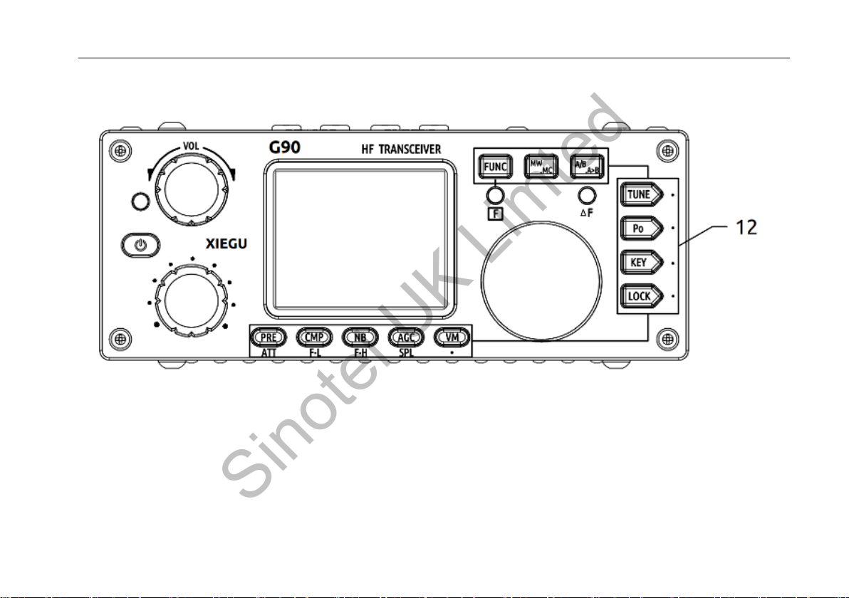
The Xiegu G90 is a portable 20W HF amateur radio transceiver with 24-bit 48 kHz SDR architecture and a built-in
automatic antenna tuner. The display panel and the main unit can be separated to enable remote mounting of the
display panel. It delivers excellent performance on both transmit and receive and is highly configurable. Standout
features include the following:
High performance front end with pre-selectable filter options;
Frequency range of 0.5-30MHz, SSB/CW/AM/ FM*1 operating modes;
30 x 35 mm high brightness full colour TFT LCD screen;
±24 kHz bandwidth spectrum display with waterfall function;
Software defined narrowband filter (CW mode: 50 Hz);
Detachable display panel;
Up to 20W RF output power;
Built-in wide range ATU;
Diversified interfaces, In particular, the baseband I/Q output allows it to interface with any external device that can handle baseband I/Q,
including sound card-based or PC-based applications such as XDT1.
In order to derive the maximum utility from your new transceiver, please read this manual carefully before use.
*1: The FM mode can only be turned on when the forthcoming GSOC controller/panadapter is used.
Sinotel UK Limted

3
X5105
T/R DATA LINK
LOCK
PRE
ATT MODE
MENU
V/M
A/B
NB RIT
ATU Po
<
①
②
③
④
⑤
⑥
⑦⑧ ⑨ ⑩
?
?
?
?
?
?
?
???
21
22
23
A
B
C
Sinotel UK Limted

4
1. Volume knob
Turn to adjust the AF volume.
Short press to switch to headphone mode.
2. Power/Receive/Transmit LED
Standby/receive status - yellow-green;
Transmitting status - red;
CW decoding status –flashes yellow.
3. Power switch
Press and hold to power on.
Press and hold to shut down.
Press briefly to cycle display on/off.
4. Multifunction adjustment Knob (MFK)
Turn to change frequency –default step is 100 kHz.
Press and hold to customize MFK operation (page 17).
5-6. Mode switching
Mode switching.
7-8. Band Switching
Band switching.
9. Function Indicator light
This indicator lights up when the second function of the
button is selected (page 21).
10. △F LED
CW decoding RX lock indicator.
11. Main Control Knob
Turning this knob will change the selected frequency
in VFO mode. In memory (channel) mode it can be
used to select stored memory channels.
Sinotel UK Limted

5
12. Function buttons
Button definitions and functions are detailed in the
operation section starting on page 21.
Sinotel UK Limted

6
13. Antenna interface
SO-239 type,impedance 50 Ω.
14. CW KEY socket
3.5mm stereo jack socket for connection of
manual/automatic CW keys.
15.Comm socket
3.5mm stereo jack socket for base unit firmware
updates.
16. I/Q Signal low level baseband output socket
3.5mm stereo jack socket to output the spectrum/waterfall
display on a PC via a soundcard with a stereo input.
17.Accessory socket
8-pin mini DIN socket for digital modes & CE-19 connection,
wiring diagram shown on page 8.
18.DC power socket
External DC power input socket.
The round hole is - , the square hole is +.
19.Ground terminal
Sinotel UK Limted

7
20. MIC Connector (Right side of the display unit)
Plug the multi-function microphone into this connector.
21.Headphone socket (Left side of the display unit)
3.5mm stereo jack socket for connecting headphones
(stereo only).
22.Communication interface (Left side of the display unit)
For firmware updates to the display unit.
Sinotel UK Limted

8
1. MIC interface
2. COMM plug
3. Headphone plug
4. ACC Socket
5. Iambic CW key wiring diagram
Note: When using a manual CW key,
connect "dit" and "da" together.
MIC
MDATA
GND
MIC
MICE PTT
MSVSW
NC
+8V
TX D
R X D G N D
信号
信号 G N D
PTTBA N D
A F_IN
A F_O U T
A LC
D A TA
+ 8V
G N D
Left channel
Right channel
Ground
Ground
RXD
TXD
Sinotel UK Limted

9
1. LOCK
2. PTT
3. UP/DOWN
4. Receive/transmit LED
5. Numeric keypad
6. FIL
7. MODE
8. Function indicator
9. Function button
10. MW
11. V/M
12. XFC
13. TUNER
Lock button
Transmit control button
Frequency up/down buttons
RX/TX operation indicator
Numeric keypad area
Filter selection
Operating mode selection
Not used
F1/F2 self-defined setting button
Memory storage operation
Frequency/channel switching
Not used
Press & hold to activate the built-in ATU
Sinotel UK Limted

10
The G90 will operate best with a 13.8V external DC power supply with a continuous current load capacity of at least 10A. The supplied power cable
must be used to connect the radio to the DC power source.
Please note the polarity of the wiring before connecting your radio to a power source. Reversing the polarity can cause damage to the transceiver
that will not be covered under warranty.
The red wire is connected to the positive terminal of the power supply, and the black wire is connected to the negative terminal.
When using an external power supply, a ferrite ring can be fitted to the power supply cable to help minimize external interference from entering the
radio, or to prevent RF from the radio being radiated via the power cable. The ferrite ring should be installed as close as possible to the radio’s power
socket.
Black wire
Red wire
Sinotel UK Limted

11
Wrap power cable twice
around the ferrite ring, as close
as possible to the radio power
socket.
Sinotel UK Limted

12
The G90 uses a multifunction menu system to access various functions. The LCD display shows functions and operating parameters as follows:
Main frequency display
Input voltage
AF Volume
Function display area
SWR meter
Signal level
Waterfall display
Status Display
Mode
VFO status
S-meter and power meter
Waterfall display
Sinotel UK Limted

13
Powering the transceiver on and off
To turn on, press and hold button.
To turn off, press and hold button for one second or more.
To turn off the display, press the
button briefly. To reactivate the display,
press again, or press any other button
or rotate any control knob.
Power button
Sinotel UK Limted

14
Frequency band selection
Press the BAND <or >buttons to cycle through the available frequency bands as follows:
3.5MHz 7.0MHz 10MHz 14MHz
18MHz
21MHz
24MHz
1.8MHz
28MHz
5.2MHz
Available frequencies may differ depending on the regulations applicable to the specific country or region in which the G90 is
sold.
The G90 covers the 10 HF Amateur bands
located between 0.5 and 30 MHz. Band- and
mode switching can be performed using the
buttons on top of the display unit or those on
the multifunction microphone.
+
-
Sinotel UK Limted

15
Operating mode selection
Different operating modes can be set for VFO-A and VFO-B.
NOTE: The FM mode can only be activated when the GSOC controller/panadapter is connected.
Press either [MODE]button to cycle through the operating
modes as follows:
:
Mode down
Mode up
Sinotel UK Limted

16
Volume Control
VOX mode
Press the [FUNC] button, then briefly press the volume knob inwards to access the VOX menu settings as follows:
VOX OFF/ON: To activate/deactivate the Vox function.
VOX GAIN: Vox Gain adjustment.
ANTI-VOX: For suppressing audio feedback between the microphone and internal speaker.
VOX DLY: Vox turn-off delay setting
The Vox function can be enabled for both the hand microphone and the line input socket. This can be useful when running digital modes
using RX and TX audio cables, as TX keying can be done automatically with the need for CAT control.
When using the AF IN port of the ACC interface for line input voice control, set the appropriate input volume level in the system menu.
This also affects the VOX level setting.
Rotate the volume knob left or right to adjust the AF
output volume.
Briefly press the volume knob inwards to select
headphone mode.
Sinotel UK Limted

17
Multifunction knob (MFK)
The operation of the multifunction knob can be customized according to your own preference.
Use of the MFK:
By default, turning the MFK will change the
selected frequency in 100 kHz steps.
To allocate a different function, press and hold the MFK for two
seconds, then rotate the main tuning knob to select one of the
options that appear on the display screen:
1) Change frequency in 100 kHz steps;
2) Squelch level;
3) Transmit power level;
4) CW key speed;
5) FFT Scale –adjusts the sensitivity of the waterfall display.
Once the desired function has been selected, press the CMP button to save or the AGC button to exit. Rotating the MFK will now adjust
the selected function.
To adjust the squelch level, briefly press the MFK, and then turn the main control knob to select the desired squelch level.
Press the MFK again to confirm.
Multi-function adjustment knob
Sinotel UK Limted

18
Setting RF TX Power
When using the G90 transceiver for the first time with a new antenna, we recommend setting the RF transmit power to
the lowest possible level to avoid damaging the transceiver due to an antenna mismatch.
Briefly press the [Po] button. The power level
will be displayed on the right hand side of the
screen. Rotate the main control knob to vary RF
TX power output in steps of 1 Watt. Press the
knob in to confirm the setting.
PO
Sinotel UK Limted

19
Setting the operating frequency (tuning)
Inputting a frequency directly using the microphone keypad:
Press the [F-INP ENT] button on the microphone. On the G90 display, the cursor will flash awaiting input;
Enter the frequency value you want to select, including point separator, and press the [F-INP ENT] button again to confirm.
For example, to set the current frequency to 14.09000MHz, key in as follows:
1. First press the [F-INP ENT] button;
2. Press the 1 4 . 0 9 0 0 0 number keys in sequence;
3. Press the [F-INP ENT] button again to confirm.
This can be done using the main control knob, the MFK
or the microphone keypad.
When using the MFK, the frequency will change
in steps of 100 kHz (this is the default stepping).
When using the main control knob, the
frequency stepping can be changed by
successive presses of the knob. The cursor on
the frequency display will move accordingly.
Main
control
Knob
Sinotel UK Limted
Other manuals for G90
10
Table of contents
Other XIEGU Transceiver manuals