Electro Industries WARMFLO WF-ANZ7 User manual

HI010
WARMFLO
®
ANALYZER
WF-ANZ7
NEW UNIT FOR
FORCED AIR & TS BOILERS
Warranty XX017

04/24/2009 2 HI010
Table of Contents
Configuration Information ………………………………….. 3
Forced Air ……………………………………………………… 5
Forced Air CFM ……………………………..………………… 9
TS Boiler
EB-S, EB-CA, EB-CO, EB-MS ………………………. 10
EB-WA, EB-WO, EB-MA, EB-MO …………………… 12
WarmFlo V4.xx Handheld
04/24/2009 3 HI010
Configuration Information – Read First
This is an upgrade for the WF-ANZ5, but this unit complies with all WarmFlo units shipped.
- Original board with 28-pin chip
- WarmFlo II board with 40-pin chip
- WarmFlo Plus board with 40-pin chip
- WarmFlo Select board with 40-pin chip
- WarmFlo TS Boiler with 40-pin chip
EB boards include:
EB-WA, EB-WO, EB-MA, EB-MO
EB-S, EB-CA, EB-CO, EB-MS
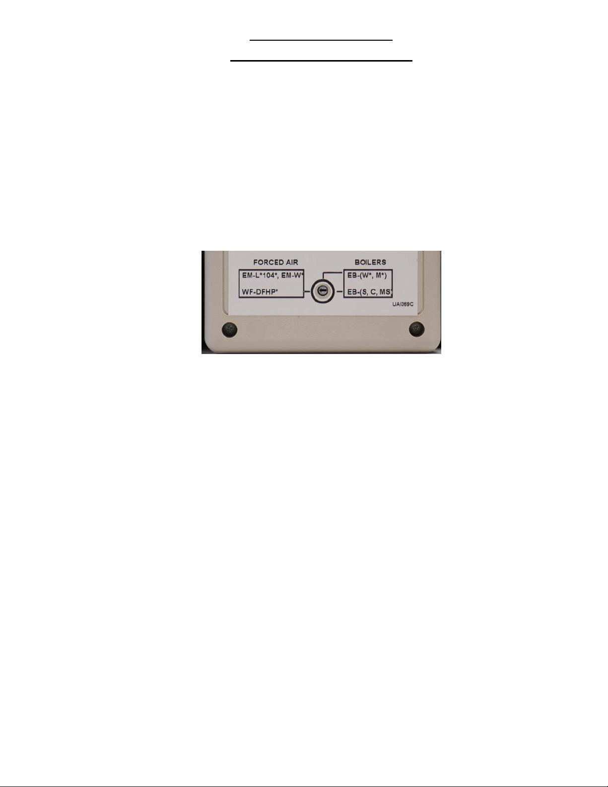
The analyzer can communicate with different WarmFlo boards. This is done by setting the rotary switch to the board type
you want to communicate with before connecting the analyzer to the board.
NOTE: For the original WarmFlo board with the 28-pin chip, select the ‘Forced-Air’
switch setting.
When the analyzer is connected the display will have “WF-ANZ7” in the top row and the analyzer software version in the
bottom row. After approximately 3 seconds the analyzer will display the type of WarmFlo board the switch is set to for
approximately 3 seconds then “PRESS MON” will appear.
When “PRESS MON” appears, press the ‘MON’ button to continue or if you hold the ‘SHIFT’ key and press the ‘0’ key, the
handheld will read the software version currently in the WarmFlo board connected. The version will stay in the display
until you press any key (except ‘SHIFT’). “PRESS MON” will then re-appear. You can press the ‘MON’ key now to
continue or press ‘SHIFT’ ‘0’ again to read the software version.
If you are connected to a WarmFlo Plus board with software version 10.xx or 12.xx or a WarmFlo Select board (version
18.xx), the configuration switch position will be displayed in parenthesis following the version number.
After the ‘MON’ key is pressed, the analyzer will check the software version against the rotary switch position on the back
of the analyzer. If you are connected to a boiler board and you have the switch in the wrong position the display will show
“SWITCH SETTING” in the top line and the boiler board software version in the bottom line. You must disconnect the
analyzer, change the switch setting and then re-connect.
Because of the different communications protocol between the boiler boards and the forced air boards, the analyzer can
not determine if you have the rotary switch in the forced air position when connected to a boiler board and vice versa. If
the analyzer gets locked up or displays “weird“ numbers then the switch is probably not set correctly.
The boiler boards have a polling scheme for communications, so it will take longer for reading and writing to these boards.
There is an internal timer in the handheld that will display “-----ERROR-----“ if, during monitoring, reading or writing, no
response is received within 10 seconds. To clear the error, press any key (except ‘SHIFT’) to restart the handheld.
If you enter a value that is not within the acceptable range the analyzer will display
“OUT OF RANGE” (on the same line as the bad entry) when you try to write to the board you are connected to.
In addition to the two-line display, the added field programmable functions are shown on the following pages grouped
according to the 3 switch settings.

WarmFlo V4.xx Handheld
04/24/2009 4 HI010
The keyboard, “SHIFT” is to allow added control functions. Similar to a typewriter keyboard, “SHIFT” refers to the upper
designated key function and must be held down while pressing the other key.
Read Mode:
1) Press and hold the ‘SHIFT’ key, then press the ‘READ’ key to enter the read mode.
2) Pressing 'MON' at any time will go to the real time monitor mode.
3) Use the LEFT and RIGHT arrow keys to move between digits in a field or if a field contains a word choice
use these keys to toggle or change the choice.
4) Use the UP/DOWN arrow key to move between the 2 lines of the display.
5) The 'CLR' key can be used to zero all digits on the display line the cursor is currently on.
This key will not change any word choices.
6) The ‘SHIFT’ + the 'SAVE' key will write the data currently displayed to the WarmFlo board.
When in the MONITOR mode pressing 'MON' again will toggle between 2 displays. Press the 'SHIFT' key plus the 'READ'
key to exit the monitor mode and go into the data entry mode.
If the sensor is not used by the program you will see ‘N/A’ instead of the temperature for that sensor. If the sensor is
detected as bad, you will see ‘BAD’ instead of the temperature for that sensor. This pertains only to the TS Boiler boards
and WarmFlo boards with a 40-pin chip.
Forced Air
04/24/2009 5 HI010
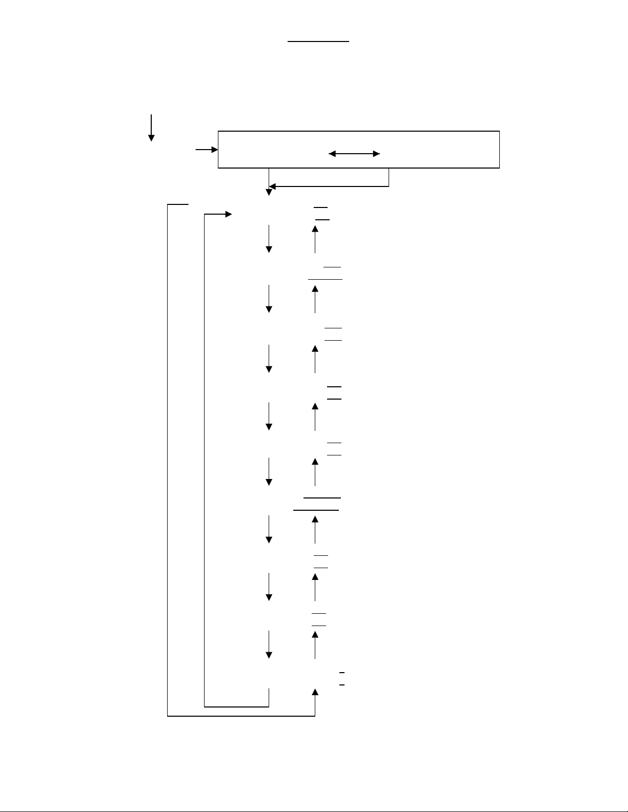
"OUTDOOR 57°F" 'MON' "DESIRED 90°F"
"SUPPLY 62°F" "PWM RATIO 100%"
POWER-UP
" PRESS MON "'MON' 'READ' 'READ'
"OT 57°F t t t °F"
"ST 62°F t t t °F"
"MU TIME mm"
"SB RESET "
"SOT-S TIME mm"
"SOT-E TIME mm"
"STG 1 OT DIS t t t"
"STG 2 OT DIS t t t"
"STG 3 OT DIS t t t"
"STG 4 OT DIS t t t"
"OT FUNC "
"ODT SW "
"OT SPD A t t t °F"
"OT SPD B t t t °F"
"ST SPD A t t t °F"
"ST SPD B t t t °F"
'PREV'
'NEXT'
'NEXT'
'NEXT'
'NEXT'
'NEXT'
'NEXT'
(± Temperature Offset)
(± Temperature Offset)
'PREV'
'PREV'
'PREV'
'PREV'
'PREV'
'PREV'
'PREV'
(Minutes)
(ENABLE or DISABLE)
'NEXT' 'PREV'
(Minutes)
(Minutes)
(-40°F to +185°F)
(-40°F to +185°F)
(-40°F to +185°F)
(-40°F to +185°F)
(DT CAL, FLAT or DISABLE)
(EL TO SB, HP ODT or HP W/STEP)
(-40°F to +185°F)
(-40°F to +185°F)
(-40°F to +185°F)
(-40°F to +185°F)
'NEXT'
WARMFLO II
WARMFLO PLUS
WARMFLO SELECT
"CT STG DISABLE s”
"CT STG DISABLE s”(0 to 4)
(0 to 4)
'NEXT' 'PREV'

Forced Air
04/24/2009 6 HI010
Monitor Mode:
1) Pressing 'READ' at any time will go to the data entry or read mode.
2) Use the 'MON' key to toggle between the 2 displays.
3) The displayed data is automatically updated every 7 seconds.
While in the monitor mode you can also hold the ‘SHIFT’ key and press ‘9’ to get to the CFM setup (see page 9).
The monitor mode data consists of:
OUTDOOR (Outdoor Temperature, OT)
SUPPLY (Supply Temperature, ST)
DESIRED (Desired Temperature, DT)
PWM RATIO
Within the WarmFlo operating module DT is calculated based upon the "Min. Warm Air" switch setting and/or the heat loss
curve built into the software. This heat loss curve takes the same shape as a typical building heat loss plot. The curve's slope
or point-by-point relationship between OT and ST is determined by specific WarmFlo chip codes or by the setting of the center
"Temperature" switch. In other words, this either represents "min. warm air" for mid or higher outdoor temperatures or the slope
(heat loss) for the lower OT values requiring DT above the "min. warm air". Thus DT is the delivery temperature required to
"heat the house" at a specific outdoor temperature.
PWM Ratio is the percentage of time stage 1 output is on. As the ST gets closer to the DT the PWM Ratio will decrease.
OT and ST (Outdoor and Supply Temperature)
(OT and ST Offset Entry)
Enter an offset to be added or subtracted from the OT and ST temperatures read from the sensors. Use the '–' key to enter an
offset to be subtracted from the sensor reading.
MU TIME
(Makeup Time)
(Enter 0-99 minutes)
An entry of 00 disables the timer.
The make up timer starts counting down when all electric stages are full on (PWM = 100%) and ST (Supply Temperature) is
less than DT (Desired Temperature) by more than 2°F. When the timer reaches 0 the board will go into the standby mode until
the Y input is removed.
SB RESET
(Standby Reset)
(Select Enable or Disable)
When the WarmFlo board goes into a standby mode, it sets a timer for 5 minutes. After this timer has expired, it checks the ST
temperature. If the ST temperature is less than 80°F, the unit will reset itself. Select ‘Enable’ if you want the board to do this
and ‘Disable’ if you do not want the board to reset.
NOTE: Unless the WarmFlo board has software version 2.21 or greater the disable function will be ignored.
It will always be enabled.
SOT-S TIME
(Enter 0-99 minutes)
An entry of 00 disables the timer.
This timer starts counting down at the beginning of heat active. If the timer reaches 0 during a continuous heat active cycle, the
board will go into the standby mode until the Y input is removed.
If both SOT-S and SOT-E times are used, SOT-S time should be greater than SOT-E time.
SOT-E TIME
(Enter 0-99 minutes)
An entry of 00 disables the timer.
This timer starts counting down at the beginning of heat active. If the timer reaches 0 during a continuous heat active cycle, the
board will default to a flat DT/HL until the Y input is removed.
If both SOT-S and SOT-E times are used, SOT-E time should be less than SOT-S time.
(See the definition of Flat under the OT Sensor Function below.)

Forced Air
04/24/2009 7 HI010
STG 1-4 OT DIS
(Stage 1-4 OT Disable Temperature)
(Enter a temperature within the range of -40°F to +185°F)
The OT sensor is used to determine summer or air conditioning function and keeps the electric elements and stand-by off even
though there may be a Y input.
Whenever the OT is greater than or equal to the entered value the stage is kept off.
OT FUNC
(OT Sensor Function)
Note: If V10.xx, V12.xx or V18.xx ‘DT CAL’ or ‘DISABLE’ will be displayed and cannot be changed.
Select from 3 choices: DT CAL, FLAT or DISABLE.
DT CAL
OT sensor will be read and its reading will be used to calculate DT.
FLAT
(Flat DT/HL)
Any heat call will step-up to a flat DT/HL (High Limit temperature).
In other words the high limit temperature will become the DT.
(The OT sensor will still be read but its reading will not be used.)
DISABLE
Electronic Aquastat mode.
The OT sensor is not read.
When changing TO this mode from one of the other 2 modes, or when changing FROM this mode to one of the other 2
modes, you must cycle power on the WarmFlo board.
ODT SW
(ODT Switch Mode)
Select from 3 choices: EL TO SB, HP ODT or HP W/STEP.
EL TO SB
If OT is less than the ODT dial switch setting, the board will go into the standby mode.
HP ODT
(HP ODT Only)
If OT is less than the ODT dial switch setting, the HP-ODT interrupt is activated.
HP W/STEP
(HP ODT With Step-Up)
Same as "HP ODT" plus the stages step-up to a flat DT/HL.
OT SPD A and B
ST SPD A and B
(Software version 2.30 and greater only)
Note:If V10.xx or 12.xx, OT SPD A and ST SPD A will display ‘N/A’ and cannot be changed.
(Enter a temperature within the range of -40°F to +185°F)
During heat active (including E), non-standby, SPD A and/or SPD B outputs are turned on if OT is less than
the temperature values for SPD A and/or B.
Once on, the outputs are left on until the end of the heat cycle.
During heat active (including E), non-standby, SPD A and/or SPD B outputs are turned on if ST is greater than
the temperature values for SPD A and/or B.
Once on, the outputs are left on until the end of the heat cycle.
ST check is done only after 30 seconds after the start of a heat cycle.
This only applies to Dual Heat I/F modules plugged into J2 (full 10 pin cable).
The temperature entered can control the furnace or air handler blower speed.
NOTE: WarmFlo Plus and WarmFlo Select have OT/ST SPD B output (tab connection)

Forced Air
04/24/2009 8 HI010
CT STG DISABLE
(Software version 10.xx, 12.xx or 18.xx only)
(Enter 0, 1, 2, 3 or 4)
Enter one or two stage numbers to disable when the CT input senses 10 amps or more.
These stages will turn OFF immediately.
When the CT input senses 5 amps or less, the stages will be re-enabled and come back ON if necessary.
If no stages are to be disabled, enter ‘0’.
When a CT input of 10 amps or more is sensed, a 30 second timer is started and the stages entered are disabled. The CT input
is now ignored until the timer expires and then the input is read again and if still active the timer restarts and the input is again
ignored for 30 seconds. This continues until the CT input senses 5 amps or less, then the input is continuously read until 10
amps or more is sensed and the timer starts again.

Forced Air
04/24/2009 9 HI010
- CFM -
WARMFLO II
WARMFLO PLUS
WARMFLO SELECT
"OUTDOOR 57°F" 'MON' "DESIRED 90°F"
"SUPPLY 62°F" "PWM RATIO 100%"
POWER-UP
" PRESS MON " 'MON' 'SHIFT 9'
"RETURN TEMP 095" 'MON' "CFM = 7586.6"
"TOTAL kW 12" "ST=100° RT= 95°"
'SHIFT MON'
CFM mode
Whenever either monitor screen is displayed, press and hold the ‘SHIFT’ key, then press the number ‘9’ key.
Enter the return temperature and the total kW.
Press the ‘MON’ key.
The calculated CFM will be displayed along with the ST temperature obtained from the circuit board and the return
temperature (RT) that you entered.
The ST temperature will be read every 5 seconds and a new calculation will be performed.
If you need to change the RT temperature, press the ‘MON’ key and you will be returned to the entry screen.
The ‘MON’ key will toggle you between the entry screen and the CFM screen.
To exit the CFM mode press the ‘MON’ key while holding down the ‘SHIFT’ key.
This will bring you back to the monitor screen.
The only way to enter the CFM mode is from either one or the two monitor screens.

TS Boiler EB-S EB-CA EB-CO EB-MS
04/24/2009 10 HI010
Note: TS Boiler EB-S and EB-CA models do not use the outdoor sensor so the temperature displayed
for “OUTDOOR” will read “N/A”.
Monitor Mode:
1) Pressing 'READ' at any time will go to the data entry or read mode.
2) Use the 'MON' key to toggle between the 2 displays.
3) The displayed data is automatically updated every 5 seconds.
The monitor mode data consists of:
OUTDOOR (Outdoor Temperature, OT)
WATER (Water Temperature, WT)
SET POINT (Set Point Temperature)
For models EB-S, EB-CA and EB-MS:
The Set Point Temperature is determined by the position of the temperature selector switch on the boiler’s front panel.
For model EB-CO:
Within the TS Boiler operating module, SET POINT is calculated based upon the heat loss curve built into the software.
This heat loss curve takes the same shape as a typical building heat loss plot. The curve's slope or point-by-point
relationship between OT and WT is determined by the setting of the "Temperature Selection" switch on the front of the
boiler. This dial switch allows field selection of 8 “curve slopes”. The setting reference point is the controlled outlet
temperature (WT) at 0°F outside. Thus SET POINT is the delivery temperature required to "heat the house" at a specific
outdoor temperature.
OT and WT (Outdoor and Water Temperature)
(OT and WT Offset Entry)
Enter an offset to be added or subtracted from the OT and WT temperatures read from the sensors. Use the '–' key to enter an
offset to be subtracted from the sensor reading.
* DELAY E HI MASS
(Enter 0 to 9 minutes)
Every ‘Delay E’ cycle the WT temperature is compared to the set point temperature to determine if any more or any less stages
should be on. The set point switch settings that are ‘Hi Mass’ are positions 0 thru 4.

TS Boiler EB-S EB-CA EB-CO EB-MS
04/24/2009 11 HI010
* DELAY E LO MASS
(Enter 0 to 9 minutes)
Same as ‘Delay E Hi Mass’ except the set point switch settings for ‘Lo Mass’ are positions 5 thru 7.
* START UP DELAY
(Enter 0 to 99 seconds)
This is the delay at the beginning of a ‘W’ heat call before determining whether or not any stages should be turned on.
* Typically these are factory only settings.

TS Boiler EB-WA EB-WO EB-MA EB-MO
04/24/2009 12 HI010
Note: TS Boiler EB-WA and EB-MA models do not use the outdoor sensor so the temperature displayed
for “OUTDOOR” will read “N/A”.

TS Boiler EB-WA EB-WO EB-MA EB-MO
04/24/2009 13 HI010
Monitor Mode:
1) Pressing 'READ' at any time will go to the data entry or read mode.
2) Use the 'MON' key to toggle between the 2 displays.
3) The displayed data is automatically updated every 5 seconds.
The monitor mode data consists of:
OUTDOOR (Outdoor Temperature, OT)
WATER (Water Temperature, WT)
SET POINT (Set Point Temperature)
PWM RATIO
For model EB-WA and EB-MA:
The Set Point Temperature is determined by the position of the temperature selector switch on the boiler’s front panel.
For model EB-WO and EB-MO:
Within the TS Boiler operating module, SET POINT is calculated based upon the heat loss curve built into the software.
This heat loss curve takes the same shape as a typical building heat loss plot. The curve's slope or point-by-point
relationship between OT and WT is determined by the setting of the "Temperature Selection" switch on the front of the
boiler. This dial switch allows field selection of 8 “curve slopes”. The setting reference point is the controlled outlet
temperature (WT) at 0°F outside. Thus SET POINT is the delivery temperature required to "heat the house" at a specific
outdoor temperature.
PWM Ratio is the percentage of time stage 1 output is on. As the ST gets closer to the DT the PWM Ratio will decrease.
OT and ST (Outdoor and Supply Temperature)
(OT and ST Offset Entry)
Enter an offset to be added or subtracted from the OT and ST temperatures read from the sensors. Use the '–' key to enter an
offset to be subtracted from the sensor reading.
MU TIME
(Makeup Time)
(Enter 0-99 minutes)
An entry of 00 disables the timer.
The make up timer starts counting down when all electric stages are full on (PWM = 100%) and ST (Supply Temperature) is
less than DT (Desired Temperature) by more than 2°F. When the timer reaches 0 the board will go into the standby mode until
the Y input is removed.
SB RESET
(Standby Reset)
(Select Enable or Disable)
When the TS Boiler board goes into a standby mode, it sets a timer for 5 minutes. After this timer has expired, it checks the ST
temperature. If the ST temperature is less than 80°F, the unit will reset itself. Select ‘Enable’ if you want the board to do this
and ‘Disable’ if you do not want the board to reset.
SOT-S TIME
(Enter 0-99 minutes)
An entry of 00 disables the timer.
This timer starts counting down at the beginning of heat active. If the timer reaches 0 during a continuous heat active cycle, the
board will go into the standby mode until the Y input is removed.
If both SOT-S and SOT-E times are used, SOT-S time should be greater than SOT-E time.
SOT-E TIME
(Enter 0-99 minutes)
An entry of 00 disables the timer.
This timer starts counting down at the beginning of heat active. If the timer reaches 0 during a continuous heat active cycle, the
board will default to a flat DT/HL until the Y input is removed.
If both SOT-S and SOT-E times are used, SOT-E time should be less than SOT-S time.

TS Boiler EB-WA EB-WO EB-MA EB-MO
04/24/2009 14 HI010
STG 1-4 OT DIS
(Stage 1-4 OT Disable Temperature)
(Enter a temperature within the range of -40°F to +185°F)
The OT sensor is used to determine summer or air conditioning function and keeps the electric elements and stand-by off even
though there may be a Y input.
Whenever the OT is greater than or equal to the entered value the stage is kept off.
BASE TEMP HI
(See Fig. 1)
(Only EBWO and EBMO software version 6.23 or greater)
(Enter a temperature between 70° and 110°F)
This is the outdoor 65°F reference or starting ramp up point for Hi Mass. The modulation supply water sensing starts at this
entry point and ramps up to the front dial 0°F reference point.
BASE TEMP LO
(See Fig. 2)
(Only EBWO and EBMO software version 6.23 or greater)
(Enter a temperature between 120° and 140°F)
This is the outdoor 65°F reference or starting ramp up point for Lo Mass. The modulation supply water sensing starts at this
entry point and ramps up to the front dial 0°F reference point.
OT FUNC
(Only EBWO and EBMO software version 6.23 or greater)
(OT Sensor Function)
Select from 3 choices: DT CAL, FLAT or DISABLE.
DT CAL
OT sensor will be read and its reading will be used to calculate DT.
FLAT
(Flat DT/HL)
Any heat call will step-up to a flat DT/HL (High Limit temperature).
In other words the high limit temperature will become the DT.
(The OT sensor will still be read but its reading will not be used.)
DISABLE
(See Table 1 and Table 2)
The OT sensor is not read.
When changing TO this mode from one of the other 2 modes, or when changing FROM this mode to one of the other 2
modes, you must cycle power on the WarmFlo board.

TS Boiler EB-WA EB-WO EB-MA EB-MO
04/24/2009 15 HI010
Temperature settings with OT sensor ENABLED Temperature settings with OT sensor DISABLED

Page 1 of 2 XX017
Electro Industries, Inc. Residential
Limited Product Warranty
Effective November 1, 2009
Electro Industries, Inc. warrants to the original owner, at the original installation site, for a period of two (2)
years fro date of original purchase, that the product and product parts anufactured by Electro
Industries, Inc. are free fro anufacturing defects in aterials and work anship, when used under
nor al conditions and when such product has not been odified or changed in any anner after leaving
the plant of Electro Industries, Inc. If any product or product parts anufactured by Electro Industries,
Inc. are found to have anufacturing defects in aterials or work anship, such will be repaired or
replaced by Electro Industries, Inc. Electro Industries, Inc., shall have the opportunity to directly, or
through its authorized representative, exa ine and inspect the alleged defective product or product parts.
Electro Industries, Inc. ay request that the aterials be returned to Electro Industries, Inc. at owner’s
expense for factory inspection. The deter ination as to whether product or product parts shall be
repaired, or in the alternative, replaced, shall be ade by Electro Industries, Inc. or its authorized
representative.
Electro Industries, Inc. will cover labor costs according to the Repair / Replace ent Labor Allowance
Schedule for a period of ninety (90) days fro the date of original purchase, to the original owner, at the
original installation site. The Repair / Replace ent Labor Allowance is designed to reduce the cost of
repairs. This Repair / Replace ent Labor Allowance ay not cover the entire labor fee charged by your
dealer / contractor.
WEN Y YEAR (20) LIMI ED WARRAN Y ON BOILER ELEMEN S AND VESSELS
Electro Industries, Inc. warrants that the boiler ele ents and vessels of its products are free fro defects
in aterials and work anship through the twentieth year following date of original purchase. If any boiler
ele ents or vessels are found to have a anufacturing defect in aterials or work anship, Electro
Industries, Inc. will replace the .
WEN Y YEAR (20) LIMI ED WARRAN Y ON SPIN FIN ELEMEN S
Electro Industries, Inc. warrants that the spin fin ele ents of its products are free fro defects in aterials
and work anship through the twentieth year following date of original purchase. If any spin fin ele ents
are found to have a anufacturing defect in aterials or work anship, Electro Industries, Inc. will replace
the .
FIVE YEAR (5) LIMI ED WARRAN Y ON OPEN WIRE ELEMEN S
Electro Industries, Inc. warrants that the open wire ele ents of its products are free fro defects in
aterials and work anship through the fifth year following date of original purchase. If any open wire
ele ents are found to have a anufacturing defect in aterials or work anship, Electro Industries, Inc.
will replace the .

Page 2 of 2 XX017
THESE WARRANTIES DO NOT COVER:
1. Costs for labor for removal and reinstallation of an alleged defective product or product parts,
transportation to Electro Industries, and any other materials necessary to perform the exchange,
except as stated in this warranty. Replacement material will be invoiced to the distributor in the usual
manner and will be subject to adjustment upon verification of defect.
2. Any product that has been damaged as a result of being improperly serviced or operated, including,
but not limited to, the following: operated with insufficient water or airflow, allowed to freeze,
subjected to flood conditions, subjected to improper voltages or power supplies, operated with airflow
or water conditions and/or fuels or additives which cause unusual deposits or corrosion in or on the
product, chemical or galvanic erosion, improper maintenance or subject to any other abuse or
negligence.
3. Any product that has been damaged as a result of natural disasters, including, but not limited to, the
following: lightning, fire, earthquake, hurricanes, tornadoes or floods.
4. Any product that has been damaged as a result of shipment or handling by the freight carrier. It is the
receiver’s responsibility to claim and process freight damage with the carrier.
5. Any product that has been defaced, abused, or suffered unusual wear and tear as determined by
Electro Industries or its authorized representative.
6. Workmanship of any installer of the product. This warranty does not assume any liability of any
nature for unsatisfactory performance caused by improper installation.
7. Transportation charges for any replacement part or component, service calls, normal maintenance;
replacement of fuses, filters, refrigerant, etc.
CONDITIONS AND LIMITATIONS:
1. If at the time of a request for service the original owner cannot provide an original sales receipt or a
warranty card registration then the warranty period for the product will have deemed to begin thirty
(30) days after the date of manufacture and NOT the date of installation.
2. The product must have been sold and installed by a licensed electrical contractor, a licensed
plumbing contractor, or a licensed heating contractor.
3. The application and installation of the product must be in compliance with Electro Industries’
specifications as stated in the installation and instruction manual, and all state and federal codes and
statutes. If not, the warranty will be null and void.
4. The purchaser shall have maintained the product in accordance with the manual that accompanies
the unit. Annually, a qualified and licensed contractor must inspect the product to assure it is in
proper working condition.
5. All related heating components must be maintained in good operating condition.
6. All lines must be checked to confirm that all condensation drains properly from the unit.
7. Replacement of a product or product part under this limited warranty does not extend the warranty
term or period.
8. Replacement product parts are warranted to be free from defects in material and workmanship for
ninety (90) days from the date of installation. All exclusions, conditions, and limitations expressed in
this warranty apply.
9. Before warranty claims will be honored, Electro Industries shall have the opportunity to directly, or
through its authorized representative, examine and inspect the alleged defective product or product
parts. Remedies under this warranty are limited to repairing or replacing alleged defective product or
product parts. The decision whether to repair or, in the alternative replace, products or product parts
shall be made by Electro Industries or its authorized representative.
THESE WARRANTIES DO NOT EXTEND TO ANYONE EXCEPT THE ORIGINAL PURCHASER AT RETAIL AND ONLY WHEN THE PRODUCT IS IN THE ORIGINAL
INSTALLATION SITE. THE REMEDIES SET FORTH HEREIN ARE EXCLUSIVE.
ALL IMPLIED WARRANTIES, INCLUDING WARRANTIES OF MERCHANTABILITY AND FITNESS FOR A PARTICULAR PURPOSE, ARE HEREBY DISCLAIMED WITH
RESPECT TO ALL PURCHASERS OR OWNERS. ELECTRO INDUSTRIES, INC. IS NOT BOUND BY PROMISES MADE BY OTHERS BEYOND THE TERMS OF THESE
WARRANTIES. FAILURE TO RETURN THE WARRANTY CARD SHALL HAVE NO EFFECT ON THE DISCLAIMER OF THESE IMPLIED WARRANTIES.
ALL EXPRESS WARRANTIES SHALL BE LIMITED TO THE DURATION OF THIS EXPRESS LIMITED WARRANTIES SET FORTH HEREIN AND EXCLUDE ANY
LIABILITY FOR CONSEQUENTIAL OR INCIDENTAL DAMAGES RESULTING FROM THE BREACH THEREOF. SOME STATES DO NOT ALLOW THE EXCLUSION OR
LIMITATION OF INCIDENTAL OR CONSEQUENTIAL DAMAGES, SO THE ABOVE LIMITATIONS OR EXCLUSIONS MAY NOT APPLY. PRODUCTS OR PARTS OF
OTHER MANUFACTURERS ATTACHED ARE SPECIFICALLY EXCLUDED FROM THE WARRANTY.
THIS WARRANTY GIVES YOU SPECIFIC LEGAL RIGHTS, AND YOU MAY HAVE OTHER RIGHTS WHICH VARY UNDER THE LAWS OF EACH STATE. IF ANY
PROVISION OF THIS WARRANTY IS PROHIBITED OR INVALID UNDER APPLICABLE STATE LAW, THAT PROVISION SHALL BE INEFFECTIVE TO THE EXTENT OF
THE PROHIBITION OR INVALIDITY WITHOUT INVALIDATING THE REMAINDER OF THE AFFECTED PROVISION OR THE OTHER PROVISIONS OF THIS WARRANTY.
Table of contents
Other Electro Industries Measuring Instrument manuals

Electro Industries
Electro Industries 1252 User manual

Electro Industries
Electro Industries Shark ST40 User manual

Electro Industries
Electro Industries Shark 100S User manual

Electro Industries
Electro Industries Nexus 1262 User manual

Electro Industries
Electro Industries Shark 200 User manual

Electro Industries
Electro Industries Shark 100S User manual

Electro Industries
Electro Industries Shark 200S Administrator Guide

Electro Industries
Electro Industries Shark 100 User manual

Electro Industries
Electro Industries Shark 200 User manual

Electro Industries
Electro Industries Shark 100 User manual


