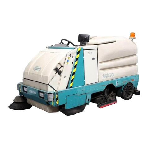
Tennant M30 User manual

M30
*9016100
*
9016100
Rev. 01 (2-2017)
(Gas/LPG)
(SN/ 008000−)
Scrubber−Sweeper
English EN
Operator Manual
The Safe Scrubbing AlternativeR
ESRExtended Scrub System
TennantTrueRParts
HygenicRFully Cleanable Tanks
FloorSmartRIntegrated Cleaning System
IRISRa Tennant Technology
Pro−PanelControls
Insta−FitAdapter
North America / International
t
For the latest Parts manuals and other
language Operator manuals, visit:
www.tennantco.com/manuals

INTRODUCTION
This manual is furnished with each new model. It provides necessary operation and maintenance instructions.
Read this manual completely and understand
the machine before operating or servicing it.
This machine will provide excellent service. However, the best results will be obtained at minimum costs if:
The machine is operated with reasonable care.
The machine is maintained regularly - per the machine maintenance instructions provided.
The machine is maintained with manufacturer supplied or equivalent parts.
Model No. −
Serial No. −
Installation Date −
Please fill out at time of installation
for future reference.
MACHINE DATAPROTECT THE ENVIRONMENT
Please dispose of packaging
materials, used components
such as batteries and fluids in
an environmentally safe way
according to local waste
disposal regulations.
Always remember to recycle.
INTENDED USE
The M30 is an industrial rider machine designed to sweep/scrub hard surfaces (concrete, asphalt, stone, synthetic,
etc). Typical applications include industrial warehouses, manufacturing facilities, distribution facilities, stadiums,
arenas, convention centers, parking facilities, transportation terminals, and construction sites. Do not use this
machine on soil, grass, artificial turf, or carpeted surfaces. This machine can be used both indoors and outdoors, but
ensure there is adequate ventilation if used indoors. This machine is not intended for use on public roadways. Do not
use this machine other than described in this Operator Manual.
Tennant Company
PO Box 1452
Minneapolis, MN 55440
Phone: (800) 553−8033
www.tennantco.com
CALIFORNIA PROPOSITION 65 WARNING:
Engine exhaust from this product contains chemicals known to the State of California to cause cancer,
birth defects, or other reproductive harm.
PerformanceView, Pro−ID, Pro−Check, Zone Settings, Thermo−Sentry, Touch−N−Go, 1−STEP, Clean−Wedge, Variable Drain Valve, EasyOpen,
Grip−n−Go, MaxPro, Dura−Track, SmartRelease, InstantAccess, Duramer, FaST−PAK, ErgoSpace, and Lower Total Cost of Ownership are trademarks
of Tennant Company.
Specifications and parts are subject to change without notice.
Original Instructions, copyright 2016, 2017 TENNANT Company, Printed in U.S.A.

CONTENTS
1
M30 Gas/LPG 9016100 (08−2016)
CONTENTS
Page
Important Safety Instructions −Save These
Instructions 3...........................
Operation 7...............................
Machine Components 7..................
Controls And Instruments 8...............
Standard Touch Panel 9..................
Pro−Panel Controls 10....................
Symbol Definitions 11.....................
Operation Of Controls −Standard Panel 14..
Fuel Indicator 14......................
Gasoline Machines 14.................
Lpg Machines 14......................
Hour Meter 14........................
Recovery Tank Full Indicator 14.........
Solution Tank Indicator 14..............
Contrast Control Button 15.............
Engine Speed Button 15................
1−Step Button 15......................
Sweeping Side Brush Button (Option) 15.
Sweeping Vacuum Fan Button 16........
Sweeping Main Brush Button 16.........
Scrubbing Side Brush Button (Option) 16.
Scrubbing Vacuum Fan /
Squeegee Button 16................
Scrubbing Main Brush Button 17........
Solution On / Off Button 17.............
Operation Of Controls −Pro−Panel 17......
Pro−Id Login Screen 17................
Machine Status Button 18..............
Changing The Default Button 19.........
1−Step Button 19......................
Sweeping Main Brush Button 20.........
Sweeping Vacuum Fan Button 20........
Sweeping Side Brush Button (Option) 20.
Scrubbing Main Brush Button 20........
Scrubbing Vacuum Fan /
Squeegee Button 21................
Scrubbing Side Brush Button (Option) 21.
Solution On / Off Buttons 21............
Engine Speed Button 22................
Zone Control Buttons 22...............
Rearview Camera Button 23............
Help Button 24........................
Video Help Button 26..................
Completing The Pro−Check
Pre−Operation Checklist 27..........
Operation Of Controls −All Machines 28....
Operating Lights 28....................
Hazard Light (Option) 28...............
Filter Shaker Switch 28.................
Operator Seat 29......................
Seat Belts 29.........................
Steering Column Tilt Knob 29...........
Brake Pedal 29.......................
Parking Brake Pedal 29................
Directional Pedal 30...................
Squeegee Protectors (Option) 30........
Page
How The Machine Works 31...............
Brush Information 32.....................
While Operating The Machine 32...........
Pre−Operation Checklist 33................
Changing The Lpg Tank 34................
Starting The Machine 35..................
Turning Off The Machine 35...............
Filling The Solution Tank 36................
Foam Scrubbing (Fast Mode) /
Ec−H2o Scrubbing (Ec−H2o Mode) 36
Conventional Scrubbing Mode 36........
Es (Extended Scrub) Mode With
Auto−Fill 37........................
Es (Extended Scrub) Mode −
Manually Filling Tanks 37............
Setting Scrub Modes 38...................
Setting Ec−H2o Mode 38...............
Setting Fast Mode 39..................
Setting Es (Extended Scrub) Mode 39....
Setting Brush Pressure 40.................
Setting Brush Pressure −
Standard Panel 40..................
Setting Brush Pressure −Pro−Panel 40..
Setting Solution Flow 41..................
Es (Extended Scrub) Solution Flow 41...
Setting Solution Flow −Standard Panel 41
Setting Solution Flow −Pro−Panel 41....
Scrubbing −Standard Panel 42............
Scrubbing −Pro−Panel 43.................
Double Scrubbing 44.....................
Water Pickup Mode (No Scrubbing) 45......
Sweeping −Standard Panel 46.............
Sweeping −Pro−Panel 47.................
Emptying The Hopper 48..................
Engaging Hopper Support Pin 49...........
Disengaging Hopper Support Pin 49........
Removing The Hopper Dust Filter 50........
Cleaning The Hopper And Debris Screen 51.
Draining And Cleaning The Recovery Tank 52
Draining The Recovery Tank With
The Drain Hose 52..................
Draining The Recovery Tank With
The Drain Plug 53..................
Draining And Cleaning The Solution Tank 54.
Faults / Alerts 56.........................
Fault / Alert Indicators −Standard Panel 56
Fault / Alert Indicators −Pro−Panel 56...
Options 58..............................
Spray Nozzle (Option) 58...............
Vacuum Wand (Option) 59..............
High Pressure Washer (Option) 60.......
Machine Troubleshooting 62...............

CONTENTS
M30 Gas/LPG 9016100 (08−2016)
2
Page
Maintenance 64.............................
Maintenance Chart 65....................
Yellow Touch Points 68....................
Lubrication 68...........................
Engine Oil 68.........................
Squeegee Caster Bearings 68..........
Front Wheel Support Bearing 68.........
Steering Cylinder Bearing 68............
Rear Wheel Bearings 69...............
Hopper Lift Arm Pivots 69..............
Hopper Door Pivots 69.................
Lift Arm Latch 69......................
Torque Tubes 69......................
Hydraulics 70............................
Hydraulic Fluid 70.....................
Hydraulic Hoses 71....................
Engine 71...............................
Cooling System 71....................
Air Filter 72...........................
Fuel Filter (Lpg) 72....................
Fuel Filter (Gasoline) 72................
Lpg Vaporizer 72......................
Engine Belt 73........................
Pcv System 73........................
Spark Plugs 73........................
Camshaft And Balance Shaft Belts 73....
Battery 73...............................
Fuses And Relays 74.....................
Relay Panel Fuses And Relays 74.......
Engine Harness Fuses And Relays 75...
Optional Relays 75....................
Circuit Breakers (Ec−H2o) 75...........
Cleaning The Hopper Dust Filter 75.........
Thermo−Sentry 76.....................
Main Brushes 76.........................
Replacing Or Rotating The Main
Brushes 76........................
Checking The Main Brush Pattern 77....
Adjusting The Main Brush Taper 78......
Adjusting The Main Brush Width 78......
Side Brush (Option) 79....................
Replacing The Side Brush 79...........
Fast System 80..........................
Replacing The Fast−Pak Carton 80......
Cleaning The Fast Supply Hose
Connector 80......................
Cleaning The Fast System Filter Screen 80
Replacing The Fast System Filters 81....
Ec−H2o Module Flush Procedure 81........
Cleaning The Ec−H2o Filter Screen 82...
Squeegee Blades 83......................
Replacing (Or Rotating) The Rear
Squeegee Blades 83................
Replacing Or Rotating The Side
Squeegee Blades 84................
Replacing Or Adjusting The Side
Brush Squeegee Blade (Option) 86...
Page
Leveling The Rear Squeegee 87.........
Adjusting The Rear Squeegee
Blade Deflection 87.................
Skirts And Seals 88.......................
Scrub Head Skirt 88...................
Recovery Tank Seal 88.................
Solution Tank Seals 88.................
Brakes And Tires 89......................
Brakes 89............................
Tires 89..............................
Front Wheel 89.......................
Propelling Motor 89.......................
Pushing, Towing, And Transporting
The Machine 90.......................
Pushing Or Towing The Machine 90......
Transporting The Machine 90...........
Machine Jacking 92......................
Storage Information 92....................
Freeze Protection (Machines Without
Ec−H2o System) 93................
Freeze Protection (Machines With
Ec−H2o System) 93................
Priming The Ec−H2o System 95.........
Specifications 96............................
General Machine Dimensions/Capacities 96.
General Machine Performance 96..........
Hydraulic System 97......................
Tires 97
Steering 97
Fast System 98
Ec−H2o System 98.......................
Machine Dimensions 99...................
Supervisor Controls 100.....................
Pro−Panel Supervisor Controls 100........
Entering The Supervisor Mode −
First Time Use Only 100...............
Entering The Supervisor Mode 101.....
Supervisor Setting Screen / Screen
Icons 102
Adding / Editing Profiles 103...........
Enabling The Login 105...............
Disabling The Login 106...............
Calibrating The Touch 106.............
Exporting Checklists 107..............
Checklist Setup 108..................
Disabling / Enabling The Pre−
Operation Checklist 109............
Changing The Rear View Camera
Settings 110......................
Programming The Zone Control
Buttons 110.......................
Setting / Changing The Date And Time 112
Index 113...................................

SAFETY PRECAUTIONS
3
M30 Gas/LPG 9016100 (08−2016)
IMPORTANT SAFETY INSTRUCTIONS −SAVE THESE INSTRUCTIONS
The following precautions are used throughout
this manual as indicated in their description:
WARNING: To warn of hazards or
unsafe practices that could result in
severe personal injury or death.
CAUTION: To warn of unsafe practices
that could result in minor or moderate
personal injury.
FOR SAFETY: To identify actions that must be
followed for safe operation of equipment.
The following information signals potentially
dangerous conditions to the operator. Know when
these conditions can exist. Locate all safety
devices on the machine. Report machine
damage or faulty operation immediately.
WARNING: Flammable materials can
cause an explosion or fire. Do not use
flammable materials in tank.
WARNING: Flammable materials or
reactive metals can cause an explosion
or fire. Do not pickup.
WARNING: Moving belt and fan. Keep
away.
WARNING: Engine emits toxic gases.
Serious injury or death can result.
Provide adequate ventilation.
WARNING: Raised hopper may fall.
Engage hopper support pin.
WARNING: Lift arm pinch point. Stay
clear of hopper lift arms.
WARNING: Burn hazard. Hot surface. Do
NOT touch.
WARNING: Do not spray people or
animals. Severe personal injury can
result. Wear eye protection. Hold
sprayer with two hands.
CAUTION: LPG engine will run for a few
seconds after key is turned off. Apply
parking brake before leaving machine.
WARNING: This machine contains
chemicals known to the State of
California to cause cancer, birth defects,
or other reproductive harm.
This machine may be equipped with
technology that automatically communicates
over the cellular network. If this machine will
be operated where cell phone use is restricted
because of concerns related to equipment
interference, please contact a Tennant
representative for information on how to
disable the cellular communication
functionality.
FOR SAFETY:
1. Do not operate machine:
−Unless trained and authorized.
−Unless operator manual is read and
understood.
−Under the influence of alcohol or
drugs.
−While using a cell phone or other
types of electronic devices.
−In dusty environments without the
vacuum fan on.
−Without filters in place or with clogged
filters.
−Unless mentally and physically
capable of following machine
instructions.
−If it is not in proper operating
condition.
−With pads or accessories not supplied
or approved by Tennant. The use of
other pads may impair safety.
−In areas where flammable
vapors/liquids or combustible dusts
are present.
−In areas that are too dark to safely see
the controls or operate the machine
unless operating / headlights are
turned on.
−In areas with possible falling objects
unless equipped with overhead guard.
2. Before starting machine:
−Check for fuel, oil, and liquid leaks.
−Keep sparks and open flame away
from refueling area.
−Make sure all safety devices are in
place and operate properly.
−Check brakes and steering for proper
operation.
−Adjust seat and fasten seat belt.
3. When starting machine:
−Keep foot on brake and directional
pedal in neutral.

SAFETY PRECAUTIONS
M30 Gas/LPG 9016100 (08−2016)
4
4. When using machine:
−Use only as described in this manual.
−Use brakes to stop machine.
−Do not pick up burning or smoking
debris, such as cigarettes, matches or
hot ashes
−Go slowly on inclines and slippery
surfaces.
−Do not scrub on ramp inclines that
exceed 10% grade or transport
(GVWR) on ramp inclines that exceed
14% grade.
−Reduce speed when turning.
−Keep all parts of body inside operator
station while machine is moving.
−Always be aware of surroundings
while operating machine.
−Do not access the video / help screens
while the machine is moving.
(Pro−Panel).
−Use care when reversing machine.
−Move machine with care when hopper
is raised.
−Make sure adequate clearance is
available before raising hopper.
−Do not raise hopper when machine is
on an incline.
−Keep children and unauthorized
persons away from machine.
−Do not carry passengers on any part
of the machine.
−Always follow safety and traffic rules.
−Report machine damage or faulty
operation immediately.
−Follow mixing, handling and disposal
instructions on chemical containers.
−Follow site safety guidelines
concerning wet floors.
5. Before leaving or servicing machine:
−Do not park near combustible
materials, dusts, gases, or liquids.
−Stop on level surface.
−Set parking brake.
−Turn off machine and remove key.
6. When servicing machine:
−All work must be done with sufficient
lighting and visibility.
−Avoid moving parts. Do not wear loose
clothing, jewelry and secure long hair.
−Block machine tires before jacking
machine up.
−Jack machine up at designated
locations only. Support machine with
jack stands.
−Use hoist or jack that will support the
weight of the machine.
−Do not power spray or hose off
machine near electrical components.
−Disconnect battery connections before
working on machine.
−Avoid contact with battery acid.
−Avoid contact with hot engine coolant.
−Do not remove cap from radiator when
engine is hot.
−Allow engine to cool.
−Keep flames and sparks away from
fuel system service area. Keep area
well ventilated.
−Use cardboard to locate leaking
hydraulic fluid under pressure.
−All repairs must be performed by a
trained service mechanic.
−Do not modify the machine from its
original design.
−Use Tennant supplied or approved
replacement parts.
−Wear personal protective equipment
as needed and where recommended in
this manual.
For Safety: wear hearing protection.
For Safety: wear protective gloves.
For Safety: wear eye protection.
For Safety: wear protective dust mask.
7. When loading/unloading machine
onto/off truck or trailer:
−Drain tanks before loading machine.
−Lower scrub head and squeegee
before tying down machine.
−Empty debris hopper before loading
machine.
−Turn off machine and remove key.
−Use ramp, truck or trailer that will
support the weight of the machine and
operator.
−Use winch. Do not drive the machine
onto/off the truck or trailer unless the
load height is 380 mm (15 in) or less
from the ground.
−Set parking brake after machine is
loaded.
−Block machine tires.
−Tie machine down to truck or trailer.

SAFETY PRECAUTIONS
5
M30 Gas/LPG 9016100 (08−2016)
The following safety labels are mounted on the
machine in the locations indicated. If these or any
labels become damaged or illegible, install a new
label in its place.
WARNING LABEL −Machine emits toxic gases.
Serious injury or death can result. Provide
adequate ventilation.
FOR SAFETY LABEL −
Read manual before
operating machine
WARNING LABEL −
Flammable materials or
reactive metals can
cause explosion or fire.
Do not pick up.
Located next to the ignition switch on the
instrument panel. (LPG machines only) Located on both hopper lift arms.
Located on the side of the operator compartment.
Located on the side
of the operator
compartment.
Located on the side
of the operator
compartment.
WARNING LABEL −Lift arm pinch
point. Stay clear of hopper lift arms
CAUTION LABEL −LPG engine will run for
a few seconds after key is turned off. Apply
parking brake before leaving machine.

SAFETY PRECAUTIONS
M30 Gas/LPG 9016100 (08−2016)
6
Located on engine
compartment panel.
WARNING LABEL −Flammable materials
can cause explosion or fire. Do not use
flammable materials in tank.
Located on the side of the bumper, on
the exhaust shield, and on the
hydraulic reservoir.
Located on both hopper lift arms.
WARNING LABEL −
Do not spray people
or animals. Severe
personal injury can
result. Wear eye
protection. Hold
sprayer with both
hands.
WARNING LABEL −Raised hopper may fall.
Engage hopper support pin.
WARNING LABEL −Burn hazard. Hot
surface. Do NOT touch
Located on frame of
machine.
Located next to the solution tank covers
and on the detergent tank.
WARNING LABEL −
Moving belt and fan.
Keep away.

OPERATION
7
M30 Gas/LPG 9016100 (08−2016)
OPERATION
MACHINE COMPONENTS
C
F
I
J
M
Q
B
A
E
H
L
N
O
P
D
G
K
R
T
S
A. Instrument panel
B. Front shroud
C. Headlights
D. Side brush (option)
E. Side squeegee
F. Scrub head access door
G. Fuel tank
H. Seat shroud
I. FaST carton, or ES detergent tank, or
ec−H2O System Module compartment
(option)
J. Solution tank cover
K. Operator seat
L. Spray wand −nozzle behind seat (option)
M. Taillights
N. Recovery tank drain hose
O. Recovery tank cover
P. Solution tank drain hose
Q. Hopper
R. Rear squeegee
S. Hopper safety pin
T. Engine cover

OPERATION
8M30 Gas/LPG 9016100 (08−2016)
CONTROLS AND INSTRUMENTS
A
B
C
D
F
I
G
H
E
J
A. Parking brake pedal
B. Brake pedal
C. Directional pedal
D. Spray nozzle switch / High pressure
washer switch (option)
E. Operating / Hazard lights switch
F. Steering column tilt knob
G. Ignition switch
H. Filter shaker switch
I. Hopper door open / close switch
J. Hopper raise / lower switch

OPERATION
9
M30 Gas/LPG 9016100 (08−2016)
STANDARD TOUCH PANEL
A
B
C
D
E
F
G
H
I
J
K
L
M
RN
O
P
Q
S
T
U
VV
WY
Z
X
A. Horn
B. Fault / Alert indicator light
C. Contrast control button
D. Fuel level indicator
E. Hour meter
F. Solution tank indicator
G. Recovery tank full indicator
H. Engine speed button
I. LCD display
J. Brush pressure button
K. Brush pressure indicator lights
L. 1−STEP button
M. ec−H2O / ES (Extended Scrub /
FaST button (Option)
N. Scrubbing buttons (indicated in blue)
O. Scrubbing main brush button
P. Scrubbing vacuum fan / squeegee button
Q. Scrubbing side brush button (Option)
R. Sweeping buttons (Indicated in brown)
S. Sweeping main brush button
T. Sweeping vacuum button button
U. Sweeping side brush button
V. Solution on / off buttons
W. Solution flow decrease button (−)
X. Solution flow indicator lights
Y. Solution flow increase button (+)
Z. USB port (Service only)

OPERATION
10 M30 Gas/LPG 9016100 (08−2016)
PRO−PANEL CONTROLS
A
HN
O
P
R
S
T
U
L
V
W
X
Y
B
C
D
E
F
G
I
J
K
M
Q
X
A. Horn
B. Fault / Alert indicator light
C. ec−H2O / ES (Extended Scrub /
FaST button (Option)
D. Machine status button
E. Help button
F. Engine speed button
G. Main brush pressure access button
H. Sweeping buttons (Indicated in brown)
I. Sweeping main brush button
J. Sweeping vacuum fan button
K. Sweeping side brush button (Option)
L. Rearview camera button
M. Solution control access button
N. Scrubbing buttons (Indicated in blue)
O. Scrubbing main brush button
P. Scrubbing vacuum fan / squeegee button
Q. Scrubbing side brush (Option)
R. 1−STEP button
S. Video help
T. Zone control 1 button
U. Zone control 2 button
V. Zone control 3 button
W. Zone control 4 button
X. Solution on / off buttons
Y. USB ports (Service only)

OPERATION
11
M30 Gas/LPG 9016100 (08−2016)
SYMBOL DEFINITIONS
These symbols are usd on the machine to identify
controls, displays, and features.
Horn Solution decrease (−)
Fault / Alert indicator Solution increase (+)
Recovery tank Solution flow
Solution tank Solution On / Off
Main brush pressure On
1−STEP Off
ES (Extended Scrub) (Option) ec−H2O (Option)
FaST (Option) Unleaded fuel only
Filter shaker Scrub mode
Operating lights / Hazard light Sweeping side brush
Headlights Sweeping vacuum fan
Spray nozzle (Option) Sweeping main brush
Scrubbing side brush Scrubbing vacuum fan / squeegee
Scrubbing main brush Jack point

OPERATION
12 M30 Gas/LPG 9016100 (08−2016)
Standard Panel Symbols
Contrast control Hour meter
Engine speed control Lower hopper
Raise hopper Hopper door close
Hopper door open
Pro−Panel Symbols
Help Zone setting 1
Zone setting 2 Zone setting 3
Zone setting 4 Hour meter
Alert / Fault Checklist item unconfirmed
Hour meter Checklist item confirmed
Login Logout
Select Supervisor settings
Rotate machine view Supervisor menu
Camera settings Start−up video

OPERATION
13
M30 Gas/LPG 9016100 (08−2016)
Pro−Panel Symbols
Control help Video help
About Video button
Backspace Video list button
Rearview camera Home (main operating screen)
Up arrow Down arrow
Disable login Back arrow
Add / Edit profiles Enable login
Operator Calibrate touch
Supervisor Checklist setup
Edit profile Export all
Add profile Export new
Delete profile Export checklists
Copy profile Enter

OPERATION
14 M30 Gas/LPG 9016100 (08−2016)
OPERATION OF CONTROLS −STANDARD
PANEL
FUEL INDICATOR
GASOLINE MACHINES
For gasoline machines, the Fuel indicator displays
the amount of fuel left in the tank. The fault
indicator will flash and a low fuel message will
appear when the tank is near empty.
NOTE: Do not use leaded fuels. Leaded fuels will
permanently damage the system oxygen sensor
and catalytic converter.
LPG MACHINES
For LPG machines, the Fuel indicator does NOT
display the amount of fuel in the LPG tank. It will
display all the indicator bars to show that some
fuel is in the tank. When the LPG tank is near
empty, the fault indicator will flash and a low fuel
message will appear.
The LPG fuel gauge on the tank displays the
amount of fuel in the LPG tank.
HOUR METER
The Hour meter records the hours the machine
was operated. Use this information to determine
machine service intervals.
RECOVERY TANK FULL INDICATOR
The recovery tank full indicator displays when the
recovery tank is full. All scrubbing functions will
stop when the recovery tank is full. Empty the
recovery tank when the indicator box is filled.
SOLUTION TANK INDICATOR
The solution tank indicator displays the amount of
liquid in the solution tank. Refill the solution tank
when the indicator box is empty. The machine will
stop scrubbing when the solution tank is empty.

OPERATION
15
M30 Gas/LPG 9016100 (08−2016)
CONTRAST CONTROL BUTTON
Use the contrast control button to darken / lighten
the LCD display.
ENGINE SPEED BUTTON
The engine speed is controlled automatically
when the 1−STEP button is pressed. When not
sweeping or scrubbing, press the engine speed
button to increase the engine RPM for increased
travel speed. Press the engine speed button
again to reduce the engine RPM.
The bars above and below the engine speed icon
indicate engine speed setting. When two thinner
bars appear above and below the icon and the
icon appears as a line figure the engine is in the
low setting.
When two thicker bars appear above and below
the engine speed icon and the thinner bars and
the icon is solid the engine is in the high setting.
1−STEP BUTTON
Press the 1−STEP button to activate all selected
sweeping and scrubbing functions. Prior to the
1−STEP button being pushed, the lights above all
the selected sweeping / scrubbing functions will
be on but the selected functions will be in the
standby mode until the 1−STEP button is
pressed. Press the 1−STEP button again when
finished cleaning to stop all scrubbing or sweeping
functions.
NOTE: The squeegee will remain down and the
vacuum fan will remain on for a few seconds to
pick up remaining water after the 1−STEP button
is deactivated.
The indicator light above the button will illuminate
when the 1−STEP button is activated.
SWEEPING SIDE BRUSH BUTTON (OPTION)
Turn on the sweeping side brush: Press the
sweeping side brush button. The indicator light will
illuminate.
Turn off the sweeping side brush: Press the
sweeping side brush button. The indicator light will
turn off.
NOTE: The sweeping side brushes cannot
operate independently from the main sweep
brushes. The main sweep brushes also come on
when the sweeping side brush button is pushed.

OPERATION
16 M30 Gas/LPG 9016100 (08−2016)
SWEEPING VACUUM FAN BUTTON
Turn on the sweeping vacuum fan: Press the
sweeping vacuum fan button. The indicator light
will illuminate.
Turn off the sweeping vacuum fan: Press the
sweeping vacuum fan button. The indicator light
will turn off.
SWEEPING MAIN BRUSH BUTTON
Turn on the sweeping main brush: Press the
sweeping main brush button. The indicator light
will illuminate.
Turn off the sweeping main brush: Press the
sweeping main brush button. The indicator light
will turn off.
NOTE: The sweeping mode and the scrubbing
mode cannot both function at the same time. The
sweeping mode will cease operating and the
scrubbing mode will begin operating if any scrub
button is pressed while the machine is in the
sweeping mode.
SCRUBBING SIDE BRUSH BUTTON (OPTION)
Turn on the scrubbing side brush: Press the
scrubbing side brush button. The indicator light
will illuminate.
Turn off the scrubbing side brush: Press the
scrubbing side brush button. The indicator light
will turn off.
NOTE: The scrubbing side brush cannot operate
independently from the main scrub brushes. The
main scrub brushes also come on when the
scrubbing side brush button is pushed.
SCRUBBING VACUUM FAN / SQUEEGEE
BUTTON
Lower squeegee and turn vacuum fan on: Press
the scrubbing vacuum fan / squeegee button. The
indicator light will illuminate.
Raise squeegee and turn vacuum fan off: Press
the scrubbing vacuum fan / squeegee button. The
indicator light will turn off.

OPERATION
17
M30 Gas/LPG 9016100 (08−2016)
SCRUBBING MAIN BRUSH BUTTON
Turn on the scrubbing main brush: Press the
scrubbing main brush button. The indicator light
will illuminate.
Turn off the scrubbing main brush: Press the
scrubbing main brush button. The indicator light
will turn off.
NOTE: The scrubbing mode and the sweeping
mode cannot both function at the same time. The
scrubbing mode will cease operating and the
sweeping mode will begin operating if any sweep
button is pressed while the machine is in the
scrubbing mode.
SOLUTION ON / OFF BUTTON
The solution flow is designed to stay on whenever
the scrub brushes are on. It can be turned off for
ten seconds with the solution on / off button to go
around corners, etc. See also SETTING THE
SOLUTION FLOW section.
Shut off the solution flow (for ten seconds) : Press
the solution on / off button. All the solution flow
indicators will turn off. (The solution flow will
automatically restart at the end of the 10 second
delay).
Turn on the solution flow: Press the solution on /
off button. The solution indicators will turn back on
and the solution flow will default to the last setting
used.
OPERATION OF CONTROLS −PRO−PANEL
PRO−ID LOGIN SCREEN
NOTE: The Pro−ID login screen only applies if the
machine was set up with it. Predefined user
accounts must be created within the Supervisor
Mode.
Use the Pro−ID login screen to log into the
machine.
Use the keypad to enter the user login number
into the display above the keypad.
Press the Enter button to log into the
machine.
Press the backspace button if necessary to
delete and reenter a number.
When the Pro−Panel is in the Supervisor Mode, a
gear symbol will appear in the lower right part of
the screen. When it is in the Operator Mode, a
video symbol will appear.

OPERATION
18 M30 Gas/LPG 9016100 (08−2016)
MACHINE STATUS BUTTON
The machine status button allows access to four
different machine status indicators. The default
display shows the fuel indicator when the machine
is turned on. Any of the four indicators can be set
as the default display until the machine is turned
off.
Press the machine status button to access all four
machine status buttons. All four machine status
buttons appear in the display for several seconds
until the default buttons reappear in the display.
For Gasoline machines: The Fuel indicator
displays the amount of fuel left in the tank.
The fault indicator will flash and a low fuel
message will appear when the tank is near
empty.
For LPG machines: The Fuel indicator does
NOT display the amount of fuel in the LPG
tank. When the LPG tank is near empty,
the fault indicator will flash and a low fuel
message will appear.
The LPG fuel gauge on the tank displays the
amount of fuel in the LPG tank.
The hour meter records the hours the
machine was operated. Use this
information to determine machine service
intervals.
The solution tank indicator displays the
amount of liquid in the solution tank. Refill
the solution tank when there are no longer
any bars shown in the display. The machine
will stop scrubbing when the solution tank is
empty.
The recovery tank full indicator displays
FULL when the recovery tank is full. All
scrubbing functions will stop when the
recovery tank is full. Empty the recovery
tank when the indicator displays FULL.
Other manuals for M30
4
Table of contents
Other Tennant Scrubber manuals

Tennant
Tennant Nobles T350 User manual

Tennant
Tennant M30 User manual

Tennant
Tennant 9021147 User manual

Tennant
Tennant T20 Gas User manual

Tennant
Tennant M17 Series User manual

Tennant
Tennant 7100 User manual

Tennant
Tennant 550 User manual

Tennant
Tennant 5400 Product manual

Tennant
Tennant T3 User manual

Tennant
Tennant 810D User manual

Tennant
Tennant M17 Series Training manual

Tennant
Tennant T1 User manual

Tennant
Tennant T300e User manual

Tennant
Tennant T17 Series Training manual

Tennant
Tennant 7300 User manual

Tennant
Tennant T591 User manual

Tennant
Tennant L2 User manual

Tennant
Tennant 5100 Product manual

Tennant
Tennant T12 User manual

Tennant
Tennant T12 Training manual