8 www.electrolux.com 9ENGLISH
8.
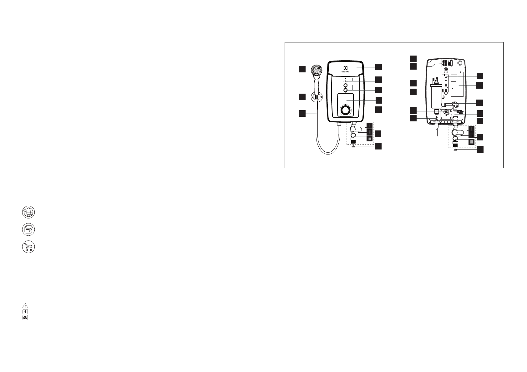
7. TEST RUN
HANDSHOWER SPRAY
9. MAINTENANCE
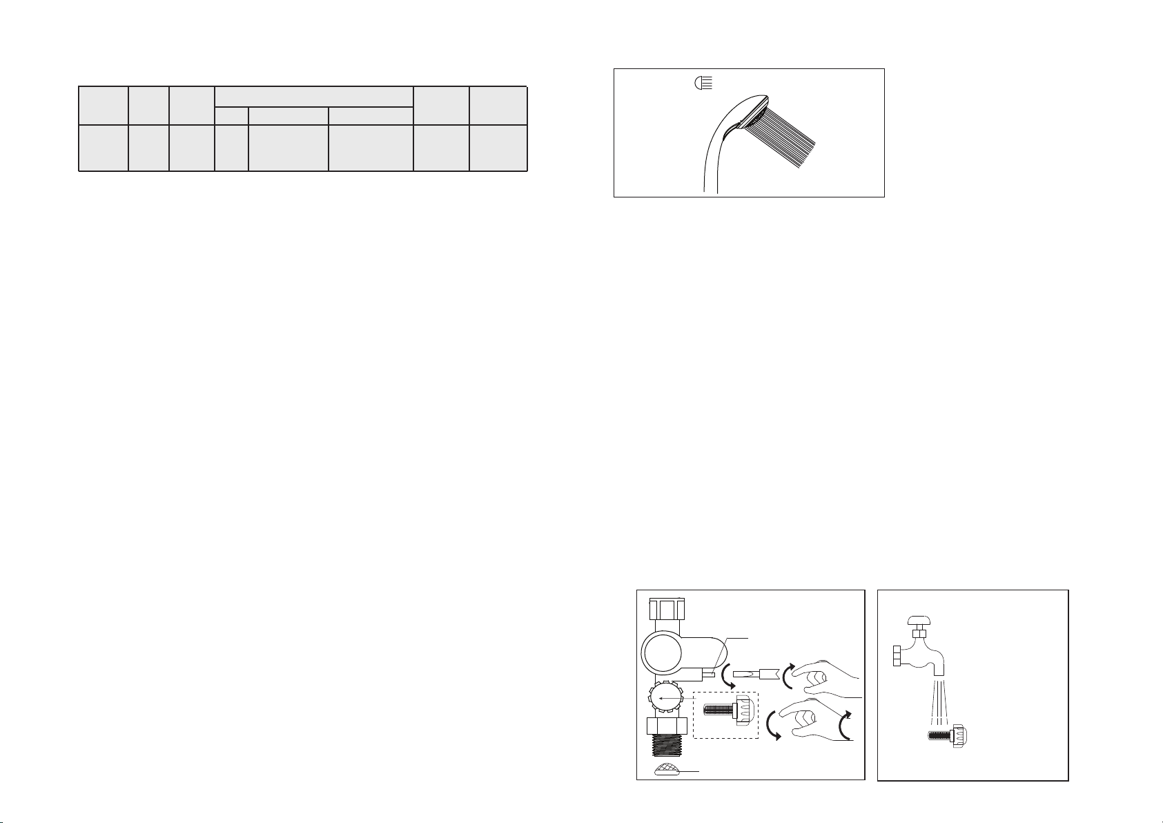
6. TABLE 1 - CABLE SIZE TABLE
9.1 TEST THE ‘ELCB’ REGULARLY
(This procedure is highly recommended test at
least once a month)
Turn on the electricity and water supply, both Red
(HEATER) and Green (ELCB) Indicators will light
up if the Temperature Control Knob is in ‘ON’
position. Press the ELCB Test Button, both
HEATER and ELCB Indicators should go off.
Press the Reset Button to resume the electricity
supply.
9.2 CLEAN THE FILTER REGULARLY
Clean the Mesh Filter regularly to prevent
blockage (Fig. 8) . Remove the Built-in Filter by
turning its cap anticlockwise. Whenever need
flush the internal stainer with water to remove any
trapped sediments. Whenever fixing back the
Built-In Filter, beware of the alignment of Internal
Strainer. Use the protruded guideline within Stop
Valve to position the Internal Strainer.
Read the section ‘ SAFETY INFORMATION ’ first. WARNING!
9.3 If the HEATER Indicator does not go off
when you press the ELCB Test Button, switch
OFF the mains supply and contact Electrolux
Call Centre for repair service. Special skill is
required for repairing. NEVER try to repair
the unit by yourself.
9.4 CLEANING PRECAUTION !
Do not use thinner,alcohol,petrol or any other
organic solutions to clean the set. Use only
damped cloth with mild detergent.
Clean the Handshower Head holes by using the soft brush from time to time.
(Recommended once a week)
Note: Take care not to damage the holes of the Handshower Head during cleaning.
Fig. 7
STANDARD SPRAY
7.1 Turn on the water supply and Stop Valve,
the water will flow through the Handshower.
7.2 Switch on the electrical supply. The 3
LED Indicator light shall run ON/OFF 3
times in sequences to indicate the set are
self checking.
If the Electric Water Heater is not earthed
properly, the Earth Led indicator light will
OFF, during usage or standby. Earth Led
indicator light also OFF if Live & Neutral
reverse connection
7.3 Turn the Temperature Control Knob to
‘ON’, the Red indicator light (HEATER
POWER) will turn on, (ELCB/Power Led
indication are combine Led indicator light-
ELCB is GREEN & Power is RED) hot water
will flow out within a few seconds. The more
Temperature Control Knob being turned in
clockwise direction, the hotter is the shower.
7.4 The shower might not be hot enough
even at the ‘MAX’ position if incoming water
supply from the mains is too cold or the
pressure of water is too high. In this case, you
may adjust the Stop Valve to reduce the water
inflow in order to get the desired showering
temperature.
7.5 Check the Built-in ELCB as following:
- Press the “TEST” Button, the Built-in ELCB
should trip and cut off the power supply, all LED
Indicators should light off.
-Press the “RESET” Button, the 3 LED Indicator
light shall run ON/OFF 3 times in sequences to
indicate self checking as in 7.2 above and the
Heater Unit should resume normal function, the
Green LED Indicator should light on.
If procedures stated above prevailed, the ELCB
is functioning in normal condition.
7.6 The height and direction of Shower
Holder are adjustable by releasing the shower
holder knob clockwise and anticlockwise.
7.7 Move the Handshower to the desired
angle. A ratchet mechanism in the Shower
Holder will hold the Handshower in selected
position.
7.8 It is unnecessary to turn the Temperature
Control Knob to “OFF” position when the
Heater is not in use.
7.9 Switch OFF the electricity supply after
shower.
Fig. 8 Fig. 9
FILTER UNIT CLEANING
CLOSE
OPEN
INTERNAL
STRAINER
OPEN CLOSE
FLOW REGULATOR
MESH FILTER
BUILT-IN FILTER
Voltage Power Current
(AC) (kW) (A)
220V ~
50/60 Hz
Conductor Size (csa)
mm Conduit Cable Flexible Cable
On/ Off Fuse /
Switch (A) MCB (A)
3.5 15.9 2.5 7 / 0.67mm 50 / 0.25 mm 32 32


 Operation and maintenance instructions")