Elements eFlex User manual

eFlex
Installation Manual
www.electricunderoorheating.co.uk
Before you begin installing read
through these instructions carefully
and check that you have all the
components required.

AD
B
C
2
The eLine Brand
Congratulations on choosing your eFlex underoor heating product from the eLine
range of underoor heating solutions.
The eLine range has been manufactured to exceed all relevant standards and
expectations considering ease of installation and usability through the lifetime of the
product.
The eFlex Product
The eFlex is a thin (4mm) twin conductor, 10w per linear metre constant wattage
heating cable, with a pre-terminated 2.5m cold tail (power cable) attached.
Twin conductor product design ensures a simple installation for either a warm oor or
total heating solution.
The xing strip provided with the eFlex kit, allows installation of the eFlex at variable
spaces (minimum 50mm) consequently altering the heat output to your own
requirements.
Tools needed for installation
You will require the following items to install and test the eFlex system:
• Tapemeasuredrawingpadandpencil
• Cablestrippersandscrewdriver
• Resistancetester(multimeter)
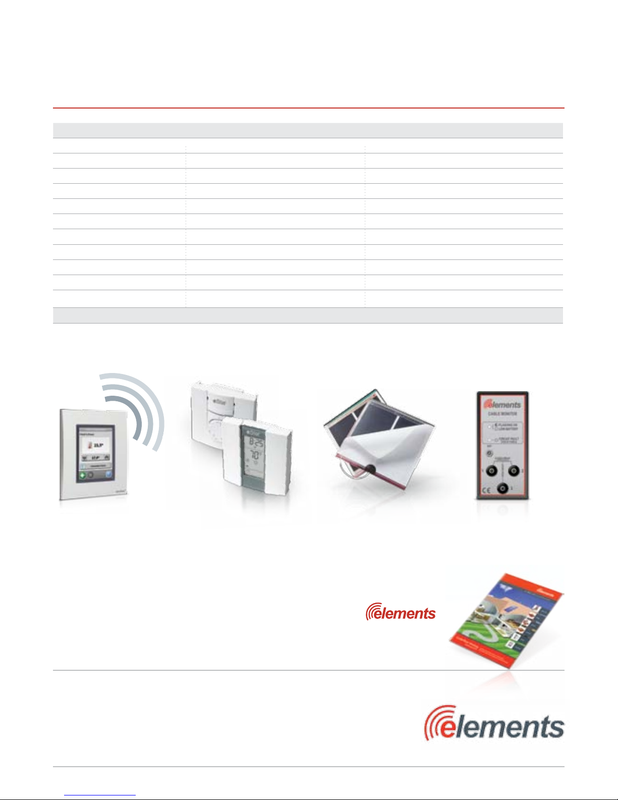
The complete eFlex system
• Heatingcable •eGaugemeasuringtape
• Sensortube •eFixdoublesidedtape
• Installationinstructions •eMesh
• Warranty
The following pages contain all the information you will need about the eFlex.
Please take time to study this information thoroughly before you attempt to install
this product.
Glossary of Terms
A– Heating element
B– Factory made cold tail joint
C– Cold tail power lead
D– End termination joint
Do’s & Don’ts
Do
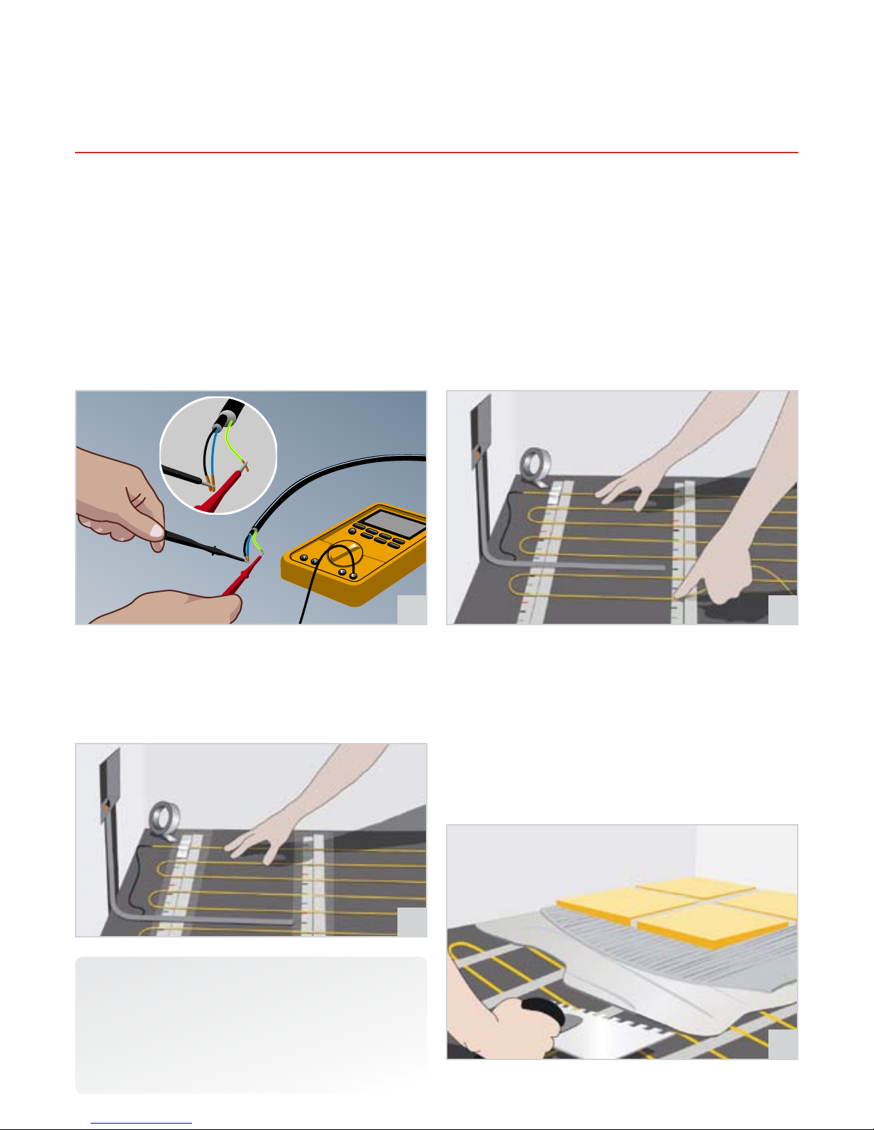
Carefully read this instruction manual before starting your installation and
follow the testing procedure as detailed on page 6.Throughout your installation:
• Takesometimetoplanyourcablelayoutconsideringallobstaclese.g.drain
covers, kitchen units, bathroom sinks etc.
• Ensuretheoorsensorthermostatisinsertedwithintheexibletube
provided, with the oor end of the exible tube properly sealed (to ensure
easy removal of the oor sensor after installation if required).
• Maintainaminimumof50mmspacingbetweentheheatingelementruns
at all times.
• Takecarenottodamagetheheatingcableandcoldtail(powercable)whilst
screeding the oor area.
• Ensurealltheyellowheatingelementiscoveredwiththetileadhesive
or exible self levelling compound.
• Ensuretheoorsurfaceiscorrectlypreparedbeforeinstallation(seepage4).
• Ensuretheentireyellowheatingelementisinstalledwithintheoor.
• WhenusingmorethanoneeFlexfromasinglesupply,coldtailsmustbe
connected in parallel.
• Whenusingfoilfacedinsulationensureallinsulationjointsareproperly
taped to prevent the eFlex from slipping in-between insulation panels.
• EnsuretheeFlexisevenlyspacedacrossyourcompletefreeoorarea.
Don’t
• Cutorshortentheyellowheatingcable.
• Crossortouchtheyellowheatingcablestogether.
• Switchyourunderoorheatingsystemonforaminimumof7daysafter
tiling to allow correct curing of tile adhesives and grouts.
• Connecttheheatingelementtothepowersupplywhilststillrolledup.
• Leaverolledupsurpluscableunderkitchenunitsorbathspaces.
•
CommenceinstallationofyouroorsurfacebeforetestingyoureFlex.Seepage7.
• Tileoverdamagedortwistedcables.
• Installheatingcablescloserthan50mm.
Introduction
Importantnotes,pleasereadcarefullybeforeproceedingwithinstallation

3
eFlex and Floor Sensor
1st Step 2nd Step
Electrical Requirements
Before installing the eFlex you should make allowance for the electrical connections.
The eFlex system requires a mains voltage 230/240V and must be connected in
accordancewiththecurrentIEEregulationsandbuildingregulationspart‘P’approved
document.
For areas up to3450Wpower connection can be provided through a 13A switched
spuroutlet/combinedRCDspuroutlet.Forlargerareasadedicatedcircuitshouldbe
installed from the local consumer unit.
Conrm your thermostat is suitable to switch the appropriate electrical
load e.g. 16A thermostat is suitable to switch up to 3450W total load.
If you are required to switch greater electrical load than 16A a suitably sized
thermostat or electrical contactor MUST BE INSTALLED. Please consult our
Help Line if in doubt 08714 740 818.
WerecommendthatalleFlexsystemsareprotectedbya30maRCDearthtripeither
attheconsumerunitorbyacombinedRCDspuroutlet.
Wheninstallinginabathroomorotherwetareasthethermostatmustbelocated
outside Zone 2 (600mm from any wet appliance e.g. shower sink etc) or outside of the
wet area ideally on the opposite face of the wall.The eFlex must be earth bonded in
accordancewiththecurrentIEEregulations.
Important. When designing your electrical installation you should always
consult an electrician concerning your requirements.
Please follow these instructions carefully. If you require assistance prior to
or during your installation please call our helpline on 08714 740 818
Electrical Requirements

Installation Instructions
4
Step 1
Drawalayoutofyourroom(seepage6)includingallobstaclese.g.Draincovers,
toilets, sinks etc, then determine the required oor area to be heated.
Decideasuitablepositionforthethermostat(startpoint)thenrefertopage6to
calculate your cable spacing and layout.
Step 2
The oor should now be prepared ready for the eFlex installation. All loose particles
should be removed and the oor thoroughly cleaned and treated with any proprietary
sealants as normally required.
Ifyourexistingoorhasabitumenorasphaltsurfaceitmusteitherberemovedor
covered with a thin exible self levelling compound, sand cement mix or insulation
panels.
When installing insulation panels ensure all joints are properly taped and
sealed to prevent the eFlex from slipping in-between any panels used.
Step 3
Directlybelowtheelectricalconnectionpointinstallthe10mmexibletube,the
exible tube must be situated in-between two cable runs (see step 6).The oor
sensing probe is installed into the exible tube to monitor the oor temperature and
mayneedtobereplacedifthesensorfails.Ensurethetubeisinstalledtoalloweasy
replacement of the sensor probe.
The exible tube in the oor
should be sealed to prevent tile adhesive or self levelling
compound entering t
hetube.Securetheexibletubeinpositionwithasectionof
robust utility tape.
Ensure your eFlex is correctly sized before you unpack the product.
Call 08714 740 818 with any questions.
Step 4
Lay the eFix double-sided adhesive tape across the oor, perpendicular to your
proposed heating cable layout, ensuring there is tape at either end of the cable
loopsandinbetween,spacedatamaximumofevery600mm.ThenlaytheeGauge
measuring tape in line with the eFix tape.
Double-sidedadhesivetape
eGauge

Installation Instructions
5
Note
After the nished oor covering has been laid perform the following tests:
•Insulationresistancetest
•Heatingcableresistancetest
•Floorsensorresistancetest
Recordyourndingsinthetest&commissionformenclosedinthebox.
Step 5
Perform the following tests: insulation resistance test, a heating cable resistance
testandaoorsensorresistancetest(seepage7),recordyourndingsinthetest&
commission form enclosed in the box.
RemovethesecuringtapefromyoureFlexrollandpositionatthestartofyoureFlex
planwithcoldtail(powercable)attheelectricalbackbox.Ensuretheseparate
thermostat oor sensor cable is inserted in to the pre-installed 10mm exible tube
andreturnedtothelowlevelelectricalbackbox.Thecoldtailjointmustbepositioned
in the oor area.
Step 6
Once the eFlex cold tail (power cable) and thermostat oor sensor probe have been
positioned you can now start to lay your heating cable. Following your previously drawn
layout and spacing, continue to lay and secure your eFlex heating cable onto the
double-sidedadhesivetapeusingtheeGaugeforguidance
. Continue laying cable until
total oor area is covered. All heating cable must
be used, any excess heating cable must
bereconguredintotheoorareabyadjusting
yourcablespacing.Ensureallheating
cables are evenly spaced across the oor area.
• Do not cut any surplus heating cable.
• Do not leave any excess heating cable spooled
or coiled in the oor area.
• Ensure all heating cable is used and spaced evenly across the oor.
Step 7
LaytheeMeshontothedoublesidedtapetosecuretheheatingcables.Further
lengthsofeMeshcanbeusedtosecuretheheatingcablebetweenthedouble-sided
tapes, if required.
Step 8
WiththeeFlexlaidandsecure,itcannowbecoveredwitheitheraexibletile
adhesive or exible self levelling compound.
Ensuringtherearenoairpockets,carefullyspreadtheexibletileadhesiveorself
levelling compound until all heating cables are covered.You may tile directly over the
eFlex, carefully applying your exible tile adhesive with a notched trowel ensuring
each tile is securely xed and all cable areas are completely covered with exible tile
adhesive.
Registeryourwarrantyonlineat:www.electricunderoorheating.co.uk/warranty

Cable Spacing and Layout Instructions
Factory end joint Thermostat
Kitchen furniture template marked onto floor
100mm border
marked onto floor
6
Cable Spacing and Layout Instructions
It is important when calculating your eFlex spacing to accurately draw
your
room area as this will help to save time and ensure a smooth installation.
1. Drawyourtotalroomareaincludingallxedfurnituresuchaskitchenunits,toilets
andsinkareas.Markyourdrawingwithallrelevantdimensions.
2. Calculate the total oor area of your room.
3.
Calculate the area taken by all the oor obstructions.
4. Calculate the free oor area by subtracting the border area from the total area.
5. Calculate the watts per m² of your installation by dividing the rated power of your
eFlex cable by the free oor area. For example, if you have 3.6m² of free floor and you
havea600Wheatingcable:
600W÷3.6m²=167W/m²
6. Using the calculated watts per m² of your room refer to the lookup table below for
an indication of the required cable spacing to ensure even cable spacing across the
floor and therefore an even heat.
eGauge Measuring Tape
TheeGaugetapeissetouttogiveyouaguidetoevenlyspaceyourheatingcable
across the oor.The coloured marks (green, blue and red) are spaced 25mm apart and
indicate one full space, the thin black lines between the coloured spacing indicate a
half spacing.
Cable space and wattage per m²
W/m² of Room Cable Spacing eGauge Spacing Guide
80W/m
²
125mm 5.5 spaces
89W/m
²
112.5mm 4.5 spaces
100W/m
²
100mm 4.0 spaces
114W/m
²
87.5mm 3.5 spaces
133W/m
²
75mm 3.0 spaces
160W/m
²
62.5mm 2.5 spaces
200W/m
²
50mm 2.0 spaces
Product Specications
Quick Find Part Code Description Wattage Resistance +9/-4%
1218 ef300 eFlex 300 300w 176.0Ω
1219 ef400 eFlex 400 400w 132.0Ω
1220 ef600 eFlex 600 600w 88.0Ω
1221 ef800 eFlex 800 800w 66.0Ω
1222 ef1000 eFlex 1000 1000w 52.9Ω
1223 ef1200 eFlex 1200 1200w 44.0Ω
1224 ef1400 eFlex 1400 1400w 37.8Ω

7
eFlex
Tile Adhesive
eGauge
Concrete sub oor
Screed
Tiles e.g. ceramic, marble,
slate, limestone etc
ePanel
insulation board
(optional)
eMesh
Timber suboor
Warranty Validation
To validate your 15 year online warranty registration you must perform the insulation resistance
test, the heating cable resistance test, and the sensor resistance test three times during the
installation process.
1. Before you lay the eFlex.
2. After you have laid your eFlex and before you cover your eFlex.
3. After your nished oor has been laid.
This information must then be recorded on your commissioning record (enclosed within the box).
Floor Construction Examples
The eFlex is a loose laid cable which can be installed beneath most ceramic, porcelain/slate and natural stone tiles.
Whenusinglaminate,engineeredtimberorvinyloorsaexibleselflevellingcompoundshouldbeused.
Heating Cable Resistance Test
This test is carried out to prove continuity of the heating
element. A low resistance ohm meter should be used
(ieMultimeteronohmsetting),connectyourmeteron
to the black and blue mains lead and conrm resistance
value matches that quoted on your specication label
ontheeFlexColdLeadjoint.
Floor Cable Resistance Test
SeeHeatingCableResistanceTestandrepeatwithoor
sensor cable.
Insulation Resistance Test
This test is performed to measure the insulation
resistance between conductors and ensures the cable
insulation is not damaged. A low resistance reading
indicates a damaged cable and must be repaired or
replaced.
The insulation resistance tester should be connected
between the conductors (blue and black cables)
and the earth cable.The meter should
record a high
resistancevaluee.g.above100Megohms.
Testing & Commissioning and Floor Construction Examples

8
The professional choice for underoor heating
Devilink
An easy to use touch screen panel which
oers complete control over your entire
heating system wirelessly from one
central control.
eStat
Provides total control and exibility
when using your underoor heating
system.Withtheoptionsofbothmanual
and fully programmable controls.
eDemist
An ultra thin self-adhesive heating
pad that ts inconspicuously behind
virtually any mirror keeping the mirror
completely mist free.
Call 01473 27 66 80 to receive the latest
underoor heating catalogue
eGuard Monitor
Monitorsmatsandcablesforfaults
during installation.
eFlex
Symptom Probable Causes Corrective action
Floor does not heat No power at controller Check power supply
MCBtripped Check the circuit is not overloaded
Thermostat not set correctly Refertothermostatinstructions
eFlex not correctly connected with thermostat Refertothermostatinstructions
Floor temperature sensor not connected Refertothermostatinstructions
Faulty sensor / thermostat ContacttheeLineHelpdesk08714740818
Heatingelementcutordamaged ContacttheeLineHelpdesk08714740818
Floor warming all the time Thermostat not set correctly Refertothermostatinstructions
Floor temperature sensor not connected Refertothermostatinstructions
Floor not getting warm enough Thermostat not set correctly Refertothermostatinstructions
Floor sensor too close to heating element ContacttheeLineHelpdesk08714740818
Contact the eLine Helpdesk with any questions on 08714 74 08 18
Troubleshooting
CopyrightElements,atradingdivisionCJElectrical(Ipswich)Limited.RegisteredinEnglandno.2895711
Tel:01473276680
Fax:01473276678
Email:info@electricunderoorheating.co.uk
Web:www.electricunderoorheating.co.uk
EdisonHouse,Unit7,
EdisonClose,RansomesEuropark,
Ipswich,Suolk,IP39GU
United Kingdom
Table of contents
Other Elements Floor Heating System manuals