manuals.online logo
Brands
  1. Home
  2. •
  3. Brands
  4. •
  5. Elenco Electronics
  6. •
  7. Test Equipment
  8. •
  9. Elenco Electronics AK-700 User guide

Elenco Electronics AK-700 User guide

Other manuals for AK-700

1

This manual suits for next models

1

Other Elenco Electronics Test Equipment manuals

Elenco Electronics RS-400/K-37 User guide

Elenco Electronics

Elenco Electronics RS-400/K-37 User guide

Elenco Electronics DT-100 User manual

Elenco Electronics

Elenco Electronics DT-100 User manual

Elenco Electronics S-3000 User manual

Elenco Electronics

Elenco Electronics S-3000 User manual

Elenco Electronics S-1325 User manual

Elenco Electronics

Elenco Electronics S-1325 User manual

Elenco Electronics SG-9000 User manual

Elenco Electronics

Elenco Electronics SG-9000 User manual

Elenco Electronics MO-1251 User manual

Elenco Electronics

Elenco Electronics MO-1251 User manual

Elenco Electronics ST-751 User manual

Elenco Electronics

Elenco Electronics ST-751 User manual

Elenco Electronics MO-1252 User manual

Elenco Electronics

Elenco Electronics MO-1252 User manual

Elenco Electronics XK-150 User manual

Elenco Electronics

Elenco Electronics XK-150 User manual

Elenco Electronics DT-100 User manual

Elenco Electronics

Elenco Electronics DT-100 User manual

Elenco Electronics TPG-70 User manual

Elenco Electronics

Elenco Electronics TPG-70 User manual

Elenco Electronics XK-700TK Installation guide

Elenco Electronics

Elenco Electronics XK-700TK Installation guide

Elenco Electronics DT-100K User guide

Elenco Electronics

Elenco Electronics DT-100K User guide

Elenco Electronics SP-3B User guide

Elenco Electronics

Elenco Electronics SP-3B User guide

Elenco Electronics RS-500 User manual

Elenco Electronics

Elenco Electronics RS-500 User manual

Popular Test Equipment manuals by other brands

Ambit P.F. Series instruction manual

Ambit

Ambit P.F. Series instruction manual

Megger BMM500 Series user guide

Megger

Megger BMM500 Series user guide

RJG Lynx Sensor Tester operating instructions

RJG

RJG Lynx Sensor Tester operating instructions

Mark-10 TT02 Series user guide

Mark-10

Mark-10 TT02 Series user guide

Martel 3001 Operator's manual

Martel

Martel 3001 Operator's manual

ElproSys DiagProg4 instruction manual

ElproSys

ElproSys DiagProg4 instruction manual

Redtech TRAILERteck T05 user manual

Redtech

Redtech TRAILERteck T05 user manual

Venmar AVS Constructo 1.0 HRV user guide

Venmar

Venmar AVS Constructo 1.0 HRV user guide

Test Instrument Solutions SafetyPAT operating manual

Test Instrument Solutions

Test Instrument Solutions SafetyPAT operating manual

Hanna Instruments HI 38078 instruction manual

Hanna Instruments

Hanna Instruments HI 38078 instruction manual

Kistler 5495C Series instruction manual

Kistler

Kistler 5495C Series instruction manual

Waygate Technologies DM5E Basic quick start guide

Waygate Technologies

Waygate Technologies DM5E Basic quick start guide

StoneL DeviceNet CK464002A manual

StoneL

StoneL DeviceNet CK464002A manual

Seica RAPID 220 Site preparation guide

Seica

Seica RAPID 220 Site preparation guide

Kingfisher KI7400 Series Training manual

Kingfisher

Kingfisher KI7400 Series Training manual

Kurth Electronic CCTS-03 operating manual

Kurth Electronic

Kurth Electronic CCTS-03 operating manual

SMART KANAAD SBT XTREME 3G Series user manual

SMART

SMART KANAAD SBT XTREME 3G Series user manual

Agilent Technologies BERT Serial Getting started

Agilent Technologies

Agilent Technologies BERT Serial Getting started

manuals.online logo
manuals.online logoBrands
  • About & Mission
  • Contact us
  • Privacy Policy
  • Terms and Conditions

Copyright 2025 Manuals.Online. All Rights Reserved.

PULSE/TONE TELEPHONE KIT
MODEL AK-700/PT-323K
Copyright © 2006, 1994 Elenco®Electronics,Inc. Revised 2006 REV-N 753700
No partof this book shall be reproduced byanymeans; electronic, photocopying, or otherwise without written permission from the publisher.
Elenco®Electronics, Inc.
Assembly and Instruction Manual
-1-
SECTION 4 - PARTS LIST
If you are a student, and any parts are missing or damaged, please see instructor or bookstore.
If you purchased this kit from a distributor, catalog, etc., please contact Elenco®Electronics (address/phone/e-
mail is at the back of this manual) for additional assistance, if needed. DO NOT contact your place of purchase
as they will not be able to help you.
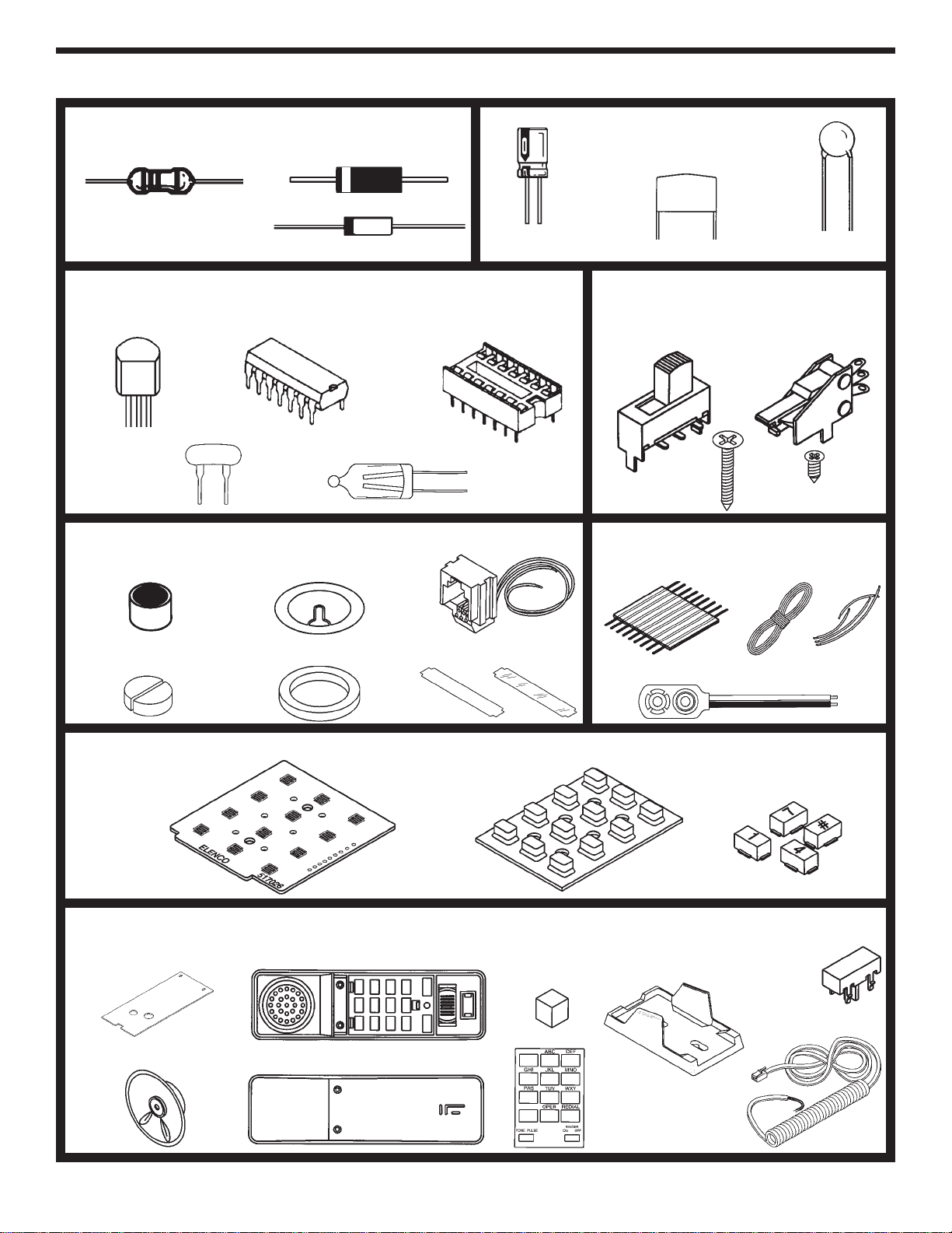
*BAG 1 *
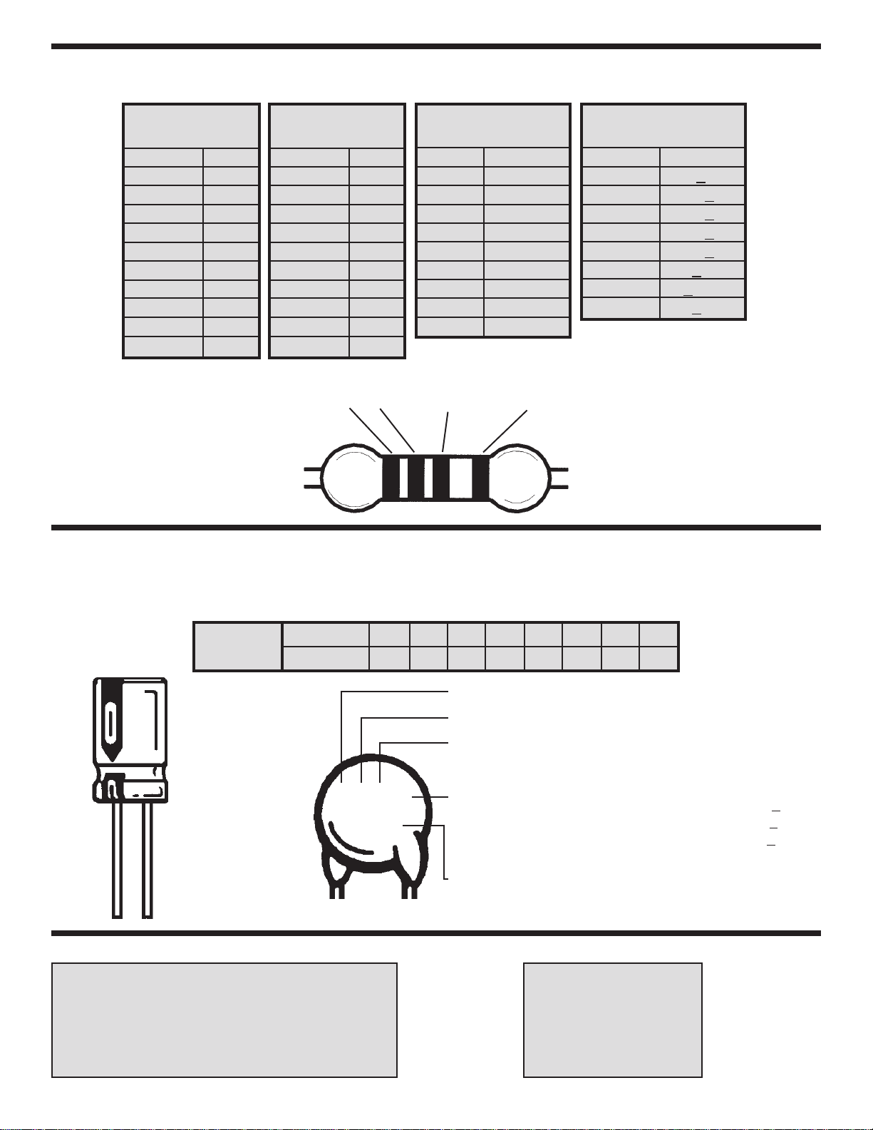
Resistors (For identifying values, refer to page 8).
QTY. SYMBOL DESCRIPTION COLOR CODE PART #
1 R18 10Ω5% 1/4W brown-black-black-gold 121000
1 R19 120Ω5% 1/4W brown-red-brown-gold 131200
1 R7 2.2kΩ5% 1/4W red-red-red-gold 142200
4 R12, R13, R15, R20 3.3kΩ5% 1/4W orange-orange-red-gold 143300
2 R5, R23 10kΩ5% 1/4W brown-black-orange-gold 151000
3 R16, R17, R22 15kΩ5% 1/4W brown-green-orange-gold 151500
4 R1 - R4 47kΩ5% 1/4W yellow-violet-orange-gold 154700
4 R6, R9, R11, R21 100kΩ5% 1/4W brown-black-yellow-gold 161000
2 R10, R14 150kΩ5% 1/4W brown-green-yellow-gold 161500
1 R8 1MΩ5% 1/4W brown-black-green-gold 171000
Diodes
QTY. SYMBOL VALUE DESCRIPTION PART #
4 D1 - D4 1N4004 or 1N4007 Diode 314004
2 D5, D6 1N4148 Diode 314148
1 D8 55C2V7/1N5223 2.7V Zener Diode 315223
1D7 55C4V7/1N5230 4.7V Zener Diode 315230
* BAG2*
Capacitors(For identifying values, refer to page 8).
QTY. SYMBOL VALUE DESCRIPTION PART #
2 C10, C11 30pF Discap (30) 213010
1 C5 300pF Discap (300 or 301) 223017
1 C2 .01µF Discap (.01 or 103) 241031
1 C8 .02µF Discap (.02 or 203) 242010
1 C7 .04µF Discap (.04 or 403) 240417
1 C1 .47µF Mylar (474/470N) 254710
1C6 1µF50V Electrolytic (Lytic) 261047
3 C3, C4, C9 47µF10V Electrolytic (Lytic) 274742
*BAG 3 *
QTY. SYMBOL VALUE DESCRIPTION PART #
1 Q2 2N5401 Transistor PNP 325401
1 Q3 2N5551 Transistor NPN 325551
1Q4 9013H Transistor NPN 329013
2Q1, Q5 9014C Transistor NPN 329014
1 IC1 HM9102 Integrated Circuit (IC) 339102
1 X Resonator 3.58MHz 560358
4 LP1 - LP4 Neon Bulb 585021
1IC1 IC Socket 18-pin 664018
-2-
*BAG 4 *
QTY. DESCRIPTION PART #
1 Switch SPDT (Hook) (S2) 541108
2 Switch SPDT (S1, S3) 541109
2 Screw 1/4” (Keyboard) 642237
2 Screw 5/8” (Case) 642477
*BAG 5 *
QTY. DESCRIPTION PART #
1 Microphone (MIC) (without leads) 568001
1 Buzzer (B) 595223
1 Modular Jack 621019
1 Label Telephone # (2 parts) 721006
1 Microphone Pad 780126
1 Buzzer Pad 780125
*BAG 6 *
QTY. DESCRIPTION PART #
1BatterySnap 9V 590098
1 Wire 22AWG Solid Yellow 6” 814420
1 Wire 26AWG Stranded Red 2” 834520
1 Wire 26AWG Stranded Red 4” 834521
4 Wire 26AWG Stranded Gray 3” 834530
1 Wire 26AWG Stranded Orange 2” 834523
1 Ribbon Cable 1” (9 wires) 879009
1 Solder 9ST4
*The Wire 22AWG SolidYellow 6” is not used.
*BAG 7 *
QTY. DESCRIPTION PART #
1 PC Board Keypad 517028
1 Push Button Set (12) 540103
1 Contact Pad Keypad 789032
*MAIN BAG *
QTY. DESCRIPTION PART #
1 PC Board Main 517027
1 Speaker (SP) 590102
1 Case Top Clear 623300
1 Case Bottom Clear 623400
1 Cradle Clear 626001
1 Hook Button Clear 626040
1Label Dial 721027
1Speaker Pad 780127
1 Telephone Cord 860900
*
-3-
PARTS IDENTIFICATION
DiodesResistor Capacitors
Transistor
Epoxy
Glass
BAG 2
Electrolytic Disc
Mylar
BAG 3
Integrated Circuit (IC) IC Socket
Resonator Neon Bulb
BAG 4
Switch SPDT
(S1, S3) Switch SPDT
(Hook) (S2)
5/8” Screw 1/4” Screw
BAG 5
Microphone
Microphone Pads
Buzzer
Buzzer Pad
Modular Jack
Label & Cover
BAG 6
Ribbon Cable Solder Wire
Battery Snap
BAG 7
Contact Keypad Push Button Set (12)
MAIN BAG
Main PC Board
Speaker (SP)
Clear Top Case
Clear Bottom Case
Keypad PC Board
Speaker
Pad
Label
Dial
Clear Cradle
Telephone Cord
Clear Hook
Button
BAG 1
-4-
IDENTIFYING RESISTOR VALUES
Use the following information as a guide in properly identifying the value of resistors.
BAND 1
1st Digit
Color Digit
Black 0
Brown 1
Red 2
Orange 3
Yellow 4
Green 5
Blue 6
Violet 7
Gray 8
White 9
BAND 2
2nd Digit
Color Digit
Black 0
Brown 1
Red 2
Orange 3
Yellow 4
Green 5
Blue 6
Violet 7
Gray 8
White 9
Multiplier
Color Multiplier
Black 1
Brown 10
Red 100
Orange 1,000
Yellow 10,000
Green 100,000
Blue 1,000,000
Silver 0.01
Gold 0.1
Resistance
Tolerance
Color Tolerance
Silver +10%
Gold +5%
Brown +1%
Red +2%
Orange +3%
Green +0.5%
Blue +0.25%
Violet +0.1%
BANDS
12 Multiplier Tolerance
IDENTIFYING CAPACITOR VALUES
Capacitors will be identified by their capacitance value in pF (picofarads), nF (nanofarads), or µF(microfarads). Most
capacitors will have their actual value printed on them. Some capacitors may have their value printed in the following
manner. The maximum operating voltage may also be printed on the capacitor.
Second Digit
First Digit
Multiplier
Tolerance The letter M indicates a tolerance of +20%
The letter K indicates a tolerance of +10%
The letter J indicates a tolerance of +5%
For the No. 01234589
Multiply By 1 10 100 1k 10k 100k 0.01 0.1
Multiplier
Note: The letter “R” may be used at times
to signify a decimal point; as in 3R3 = 3.3
103K
100V
Maximum Working Voltage
The value is 10 x 1,000 = 10,000pF or .01µF100V
10µF 16V
METRIC UNITS AND CONVERSIONS
Abbreviation Means Multiply Unit By Or
p Pico .000000000001 10-12
n nano .000000001 10-9
µmicro .000001 10-6
m milli .001 10-3
– unit 1 100
k kilo 1,000 103
M mega 1,000,000 106
1. 1,000 pico units = 1 nano unit
2. 1,000 nano units = 1 micro unit
3. 1,000 micro units= 1 milli unit
4. 1,000 milli units = 1 unit
5. 1,000 units = 1 kilo unit
6. 1,000 kilo units= 1 mega unit
SECTION 1 - INTRODUCTION
The Model AK-700 / PT-323K is a push button electronic telephone kit. Your telephone is equipped with the
following features: A) a tone/pulse switch, B) automatic redial (for pulse dialer) of up to 32 digits, C) a ringer
turn off switch, and D) four neon bulbs to give a visual indication that the telephone is ringing. The kit is built up
in three sections: 1) Ringer, 2) Transmit-Receive, and 3) Dialer. As each section is added, its function is
explained and tests are run to demonstrate its operation.
FCC regulations do not allow the Model AK-700 / PT-323K Telephone to be connected to the telephone network
unless it has been either assembled under the supervision of an instructor or been tested by Elenco®.
SECTION 2 - FCC REQUIREMENTS
For the last several years, the Federal Communications Commission (FCC) has provided the standards for the
protection of the telephone network from harm caused by the connection of terminal equipment. The rules
established require that all terminal equipment, such as your telephone, be registered with the FCC. The FCC
registration number of your telephone is GXA3PP-19545-TE-E.
If trouble is experienced, the telephone must be removed from the telephone network to determine if it is
malfunctioning. If it is malfunctioning, the telephone must not be reconnected to the telephone network until
repairs are made. Repairs should be made by Elenco®. To arrange for repairs, contact Elenco®at the address
given on the backof this manual.
SECTION 3 - GENERAL DESCRIPTION
The primary purpose of the telephone is to transmit and receive voice signals allowing two people with
telephones to communicate with each other. To be of practical value, the telephone must be connected to a
switching network capable of connecting each telephone to many other telephones. To accomplish this switching,
each subscriber telephone is connected to the telephone company’s Central Office by two wires referred to as
the “Local Loop”. A simplified diagram of this connection is shown in Figure 3-1. The Tip and Ring designation
of the + and – leads come from the days of the manual switchboard. The tip of the plug the operator used to
connect telephones carried the (+) lead and the ring immediately behind the tip carried the (–) lead.
When a subscriber wishes to place a call, they merely pick up the telephone and a small current flows in the
local loop. This current picks a relay in the Central Office indicating that service is being requested. When the
Central Office is ready to accept the number being called, a dial tone is sent to the calling telephone. The dial
pulses, or tones, then signal to the Central Office the number of the telephone being called. A path is then
established to that telephone. This path may be a simple wire connection to a telephone connected to the same
Central Office or it maygo via wire, microwave link, or satellite to a telephone connected to a distant Central
Office. To signal the incoming call, a ringing signal is placed on the local loop of the called telephone. The
ringing signal is a 90 VAC 20Hz signal superimposed on the 48VDC present on the local loop. A ringing tone
is also sent to the calling telephone. When the called party picks up the telephone, voice communication is
established.
-5-
The Rotary Dial Telephone
Asimplified schematic diagram of the
traditional rotary dial telephone is shown in
Figure 3-2. The major parts of this telephone
are explained below. Your kit is a newer
electronic type telephone. When you build
your telephone in Section 6, you will notice
several differences between the traditional and
electronic type telephones.
Hook Switch
When the hook switch is open (on hook) no
current flows in the local loop. The 48VDC
from the battery in the Central Office appears
on the tip and ring input to the telephone set.
When the receiver is lifted, the hook switch
closes and a current of about 20 to 120mA
flows in the local loop. The resistance of the
local loop drops the voltage at the telephone to
about 6 volts. The current picks a relay in the
Central Office which tells other equipment
there that service is being requested. When
the Central Office is ready to accept the
number being called, a dial tone is sent to the
calling telephone. The dial tone stops when
the first digit is dialed.
Dialer
There are twotypes of dialers, pulse and tone.
Pulse Dialer
Pulse dialing is accomplished by the familiar rotary dial shown in Figure 3-2. The dial is rotated to the stop and
then released. A spring in the dialer returns the dial to its null position. As the dial returns, the dial switch (S2)
opens and closes at a fixed rate. This switch is in series with the hook switch. Opening the switch interrupts the
current in the local loop. A series of current pulses is thus sent out on the local loop as shown in Figure 3-3. The
number of pulses sent corresponds to the digit dialed. Dialing “0” sends ten pulses. The dial pulses are sent at
a rate of 10 pulses per second (100 ms. between pulses). Each pulse consists of a mark interval (loop current)
and a space interval (no loop current). In America, the mark interval is 40 ms. and the space interval is 60 ms.
giving a mark/space ratio of 40/60. In Europe, the mark space ratio is usually 33/67.
-6-
Figure 3-1
Figure 3-2
Figure 3-3
Tone Dialer
Tone dialing is accomplished with a keyboard of 12
keys arranged in 4 rows and 3 columns. As seen in
Figure 3-4, low frequencies of 697, 770, 852 and
941 are associated with rows R1 through R4 and
high frequencies of 1209, 1336 and 1477Hz are
associated with columns C1 through C3. To send
each digit, two frequencies are sent to the Central
Office simultaneously. For this reason, this method
of dialing is referred to as Dual Tone Multifrequency
(DTMF). The different frequencies are generated by
connecting a capacitor to different taps of a
transformer to establish a resonant circuit of the
correct frequency. Each of the 3 keys of row 1 are
mechanically connected to switch SR1. Similarly,
each of the other rows and columns are connected
to their corresponding switch. Thus, pressing any
key closes two switches and generates two
frequencies. Pressing a 6 for example, closes
switches SR2 and SC3 and generates 770 and
1477Hz.
Transmitter
The Transmitter consists of a metal diaphragm and a metal case insulated from each other as shown in Figure 3-5.
The case is filled with carbon granules. When you speak into the transmitter, the sound waves of your voice strike
the diaphragm and causes it to vibrate. This causes the carbon granules to compress and expand. When
compressed, the resistance of the carbon granules is less than when expanded. The change of resistance causes
acorresponding change in the current. The current thus varies in step with the sound waves of your voice.
-7-
Figure 3-4
Figure 3-5
-8-
Receiver
There are several different types of receivers. In principle, they
work the same as the speakers in your radio andTV. The speaker
consists of a small coil attached to a diaphragm. The coil is
mounted over a permanent magnet as shown in Figure 3-6. Coil
current in one direction causes the coil and diaphragm to be
repelled from the permanent magnet. Coil current in the other
direction causes the coil and diaphragm to be attracted to the
permanent magnet. If a current of audio frequency is sent
through the coil, the diaphragm vibrates and generates sound
waves in step with the current. Thus, if the current from the
transmitter is sent through the coil, the sound produced will
duplicate the sound striking the transmitter.
Ringer
As shown in Figure 3-2, the ringer is connected across the tip
and ring inputs in series with a capacitor to block the 48VDC.
The ringer consists of a permanent magnet attached to an
armature as shown in Figure 3-7. When an alternating current
of 20Hz is passed through the coils, the armature is alternately
attracted to one coil and then the other. The hammer attached
to the armature thus strikes one bell and then the other to
produce the ringing sound.
Induction Coil / Balance Network
When transmitting and receiving is done over the same two
wires,the problem arises that current from the transmitter flows
through the receiver. The speaker then hears their own voice
from the receiver. This is called sidetone. Too much sidetone
maybe objectionable to the speaker and cause them to speak
too softly. A small amount of sidetone is desirable to keep the
telephone from sounding dead.
The induction coil and balance network limit the sidetone. The impedance of the balance network shown in
Figure 3-2 approximately matches the impedance of the local loop. Thus, about half of the current from the
transmitter flows through L1 and the local loop and the other half flows through L2 and the balance network. The
currents in L1 and L2 induce voltages in L3 of opposite polarity which limits the voltage across the receiver to an
acceptable level. When receiving a signal from the local loop, the currents in L1 and L2 induce voltages in L3 of
the same polarity. These voltages combine to drive the receiver.
Figure 3-6
Figure 3-7
-9-
Introduction
The most important factor in assembling your Tone/Pulse Telephone Kit is good soldering techniques. Using
the proper soldering iron is of prime importance. A small pencil type soldering iron of 25 - 40 watts is
recommended.The tip of the iron must be kept clean at all times and well tinned.
Safety Procedures
• Wear eye protection when soldering.
•
Locate soldering iron in an area where you do not have to go around it or reach over it.
•Do not hold solder in your mouth. Solder contains lead and is a toxic substance. Wash your hands
thoroughly after handling solder.
• Be sure that there is adequate ventilation present.
Assemble Components
In all of the following assembly steps, the components must be installed on the top side of the PC board unless
otherwise indicated. The top legend shows where each component goes. The leads pass through the
corresponding holes in the board and are soldered on the foil side.
Use only rosin core solder of 63/37 alloy.
DO NOT USE ACID CORE SOLDER!
CONSTRUCTION
Solder Soldering Iron
Foil
Solder
Soldering Iron
Foil
Component Lead
Soldering Iron
Circuit Board
Foil
Rosin
Soldering iron positioned
incorrectly.
Solder
Gap
Component Lead
Solder
Soldering Iron
Drag
Foil
1. Solder all components from
the copper foil side only.
Push the soldering iron tip
against both the lead and
the circuit board foil.
2. Apply a small amount of
solder to the iron tip. This
allows the heat to leave the
iron and onto the foil.
Immediately apply solder to
the opposite side of the
connection, away from the
iron. Allow the heated
component and the circuit
foil to melt the solder.
1. Insufficient heat -the
solder will not flowonto the
lead as shown.
3. Allowthe solder to flow
around the connection.
Then, remove the solder
and the iron and let the
connection cool. The
solder should have flowed
smoothly and not lump
around the wire lead.
4.
Here is what a good solder
connection looks like.
2. Insufficient solder -let the
solder flow over the
connection until it is
covered. Use just enough
solder to cover the
connection.
3. Excessive solder -could
make connections that you
did not intend to between
adjacent foil areas or
terminals.
4. Solder bridges -occur
when solder runs between
circuit paths and creates a
short circuit. This is usually
caused by using too much
solder. To correct this,
simply drag your soldering
iron across the solder
bridge as shown.
What Good Soldering Looks Like
Agood solder connection should be bright, shiny,
smooth, and uniformly flowed over all surfaces.
Types of Poor Soldering Connections