elero Patio User manual

Linearantrieb / Linear actuator / Vérin électrique /
Motore lineare / Motor lineal
Patio
Stand 04/2018, TN: 2011815
Operating instructions
Please take care of the operating instructions!
Montageanleitung
Bitte bewahren Sie die Montageanleitung auf!
DE
Instructions de montage
Veuillez conserver les présentes instructions de montage!
FR
Istruzioni per l‘uso
La preghiamo di conservare le istrzioni per l‘uso!
IT
Instrucciones de montaje
Por favor, conserve estas instrucciones de montaje!
ES
EN

DE Die deutsche Montageanleitung ist die Originalfassung.
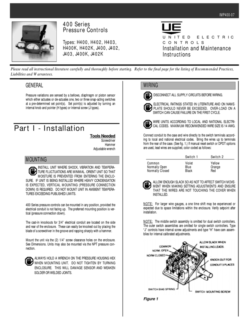
Alle anderssprachigen Dokumente stellen Übersetzungen der Originalfassung
dar.
Änderungen vorbehalten. Alle Rechte für den Fall der Patent-, Gebrauchs-
muster- oder Geschmacksmustereintragung vorbehalten.
EN Translation from the original German version.
All other documents in different languages are translations of the original
version.
Subject to change without notice. All rights reserved in the event of registrati-
on of patents, working models or design patents.
FR Traduction à partir des instructions de montage
d‘origine en langue allemande.
Tous les documents dans une autre langue sont des traductions à partir de
l‘édition d‘origine.
Sous réserve de modifications. Tous droits réservés pour l‘enregistrement de
brevet, de modèle d‘utilité ou de modèle déposé.
IT Traduzione dalla versione originale in lingua tedesca.
Tutti i documenti redatti in altre lingue sono traduzioni dalla versione originale.
Con riserva di modifica. Tutti i diritti riservati per la registrazione di marchi
registrati, disegni o modelli di utilità.
ES Traducción del original alemán.
Los documentos en otras lenguas son traducciones de la versión original en
alemán.
Reservado el derecho a realizar modificaciones. Reservados todos los
derechos de registro de patentes, modelos de utilidad o modelos o diseños
industriales.

Table of Contents
EN
Table of Contents
1 General................................................................................................3
1.1 Notes on the installation instructions ............................................................... 3
1.2 Standards and guidelines................................................................................. 3
1.3 Intended use..................................................................................................... 3
1.4 Foreseeable misuse ........................................................................................ 4
1.5 Warranty and liability ........................................................................................ 4
1.6 Customer service of the manufacturer ............................................................. 5
1.7 Installationcerticate........................................................................................ 5
2 Safety ..................................................................................................6
2.1 General safety information ............................................................................... 6
2.1.1 Formulation of safety information ..................................................................... 6
2.2 Safety principles ............................................................................................... 8
2.3 General duties of the operator.......................................................................... 9
2.4 Requirements for personnel ............................................................................. 9
2.5 Safety information on the technical condition................................................. 10
2.6 Safety information on transport, assembly and installation ............................ 10
2.7 Safety information on operation.......................................................................11
2.8 Safety information on the electrical installation ...............................................11
3 Product description ......................................................................... 12
3.1 General........................................................................................................... 12
3.2 Technicalspecications.................................................................................. 13
3.2.1 Summary of the technical parameters............................................................ 13
3.2.2 Information on the self-locking facility............................................................. 14
4 Installation ........................................................................................15
4.1 Installation and connection............................................................................. 16
4.2 Electrical connection....................................................................................... 17
4.2.1 Parallel connection ......................................................................................... 18
4.2.2 Minimum current of customer-provided power supply for each device .......... 18
4.3 Mechanical limit positions............................................................................... 18
4.3.1 Operation of the device .................................................................................. 18

Table of Contents
5 Waste disposal .................................................................................19
5.1 Scrapping ....................................................................................................... 19
5.2 Disposal of electrical and electronic components .......................................... 19

25
General
EN
1 General
1.1 Notes on the installation instructions
Theclassicationofthecontentsisbasedonthelifestagesofthelineardrive
(hereinafter referred to as the “device”).
Themanufacturerreservestherighttomakechangestothetechnicalspeci-
cations stated in these installation instructions. They may differ slightly from the
respective version of the device without the factual information being fundamen-
tallychangedorlosingvalidity.Thecurrentstatusofthetechnicalspecications
can be requested from the manufacturer at any time. Claims may not be asser-
ted in this respect. Deviations from the text and images are possible and depend
on the technical development, equipment and accessories of the device. The
manufacturer shall provide information on any differing details relating to special
versionsbymeansofthesalesdocumentation.Otherspecicationsshallremain
unaffected by this.
1.2 Standards and guidelines
The basic health and safety requirements of the applicable laws, standards and
guidelines were applied during the design phase.
ThesafetyofthedeviceisconrmedbytheDeclarationofIncorporation(see
chapter “Declaration of Incorporation”). All information relating to safety in these
installation instructions refers to the laws and regulations that are currently valid
in Germany. All information in these installation instructions must be complied
with at all times and without limitation. In addition to the safety information in
these installation instructions, the regulations applicable at the place of installa-
tion with regard to accident prevention, environmental protection and occupati-
onal safety must be observed and adhered to. The guidelines and standards for
safety assessment can be found in the Declaration of Incorporation.
1.3 Use in line with intended use
Thedeviceisdesignedforuseinsunlightandshadesystems.Othereldsof
application must be agreed in advance with the manufacturer.
The device must not be used in areas where there is danger to personnel or in
potentially explosive environments.

26
General
If direct or indirect danger to personnel cannot be ruled out, additional measures
(e.g. covers, barriers, etc.) must be taken in order to minimise the potential risk
accordingly.
The operator alone is liable for any damage resulting from non-intended use of
the device. The manufacturer assumes no liability for personal injury or damage
to property caused by misuse or procedural errors, improper operator control
or improper start of operation. The device may only be operated by trained and
authorised specialist personnel who observe all of the safety information.
Safe and error-free use of the device and its operational safety can only be
guaranteed if the device is used as intended, in accordance with the information
in this installation manual.
Intended use includes observation of and adherence to all of the safety infor-
mationspeciedintheseinstallationinstructions,aswellasallapplicableregu-
lations of trade associations and the applicable laws concerning environmental
protection. Use in compliance with the intended use also includes adherence to
the operating regulations prescribed in these installation instructions.
1.4 Foreseeable misuse
Installation deviating from the intended purpose approved by the manufacturer
is considered foreseeable misuse.
1.5 Guarantee and liability
Theguaranteeperiodsspeciedinthemanufacturer'sGeneralTerms&Condi-
tionsofSaleandDeliveryapply.TheTerms&ConditionsofSaleandDelivery
are part of the sales documentation and are given to the operator at the time of
delivery. Liability claims for personal injury and damage to property are excluded
if they can be attributed to one or more of the following causes:
• The customer opening the device (breaking the seal)
• Improper use of the device
• Improper installation, commissioning or operation of the device
• Structuralmodicationstothedevicewithoutthewrittenapprovalofthe
manufacturer
• Operation of the device with incorrectly installed connections, defective
safetydevicesorincorrectlyttedsafetyandprotectiondevices
• Non-compliance with the safety regulations and information provided in
these installation instructions

27
General
EN
• Exceedingthelimitsofthetechnicalspecications
1.6 Customer service of the manufacturer
The device may be repaired only by the manufacturer in the event of a fault.
The address for sending the device to the customer service department can be
found on the inside of the back cover.
If you have not purchased the device directly from elero, please contact the
manufacturer of the machine or the supplier of the device.
Mechanically secure the machine before dismantling the device. The device
must not be separated from the machine by force.
Please have the serial number ready on request from customer services. This
can be found in the top right-hand half of the type plate.
1.7 Declaration of Incorporation
The Declaration of Incorporation in accordance with 2006/42/EC is available to
download online at www.elero-linear.de in the Service area.

28
Safety
2 Safety
2.1 General safety notices
These installation instructions contain all of the safety information that must be
observed in order to avoid and prevent hazards when working with the device at
any stage in its individual life cycles. Safe use of the device is guaranteed when
all the safety information provided is adhered to.
2.1.1 Formulation of safety information
The safety notices in this document are marked with safety symbols and formu-
latedinaccordancewiththeSAFEprinciple.Theycontainspecicationsrelating
to the type and source of danger, the possible consequences, as well as the
prevention of the danger.
The following table provides the illustrations and descriptions used in these
installation instructions to indicate the levels of danger and the potential physical
injuries arising from them.
Symbol
Keyword
Meaning
DANGER Warns of an accident that will occur if the in-
structions are not followed, which can lead to
life-threatening, irreversible injuries or death.
WARNING Warns of an accident that may occur if the
instructions are not followed, which can lead
to serious, potentially life-threatening, irrever-
sible injuries or death.
CAUTION Warns of an accident that may occur if the
instructions are not followed, which can lead
to minor, reversible injuries.

29
Safety
EN
The following table provides the images used in these installation instructions to
visually represent the hazard situations together with the symbols used to indi-
cate the level of danger.
Symbol
Meaning
Danger from electrical voltage - risk of electric shock:
This symbol refers to dangers associated with electrical
currents.
Danger of crushing and fatal injuries:
This symbol indicates dangerous situations in which the en-
tire body or individual limbs can become crushed or injured.
The following table provides the illustrations and descriptions used in these in-
stallation instructions to indicate situations in which damage to the product may
occur or highlights important facts, statuses, tips or information.
Symbol
Keyword
Meaning
WARNING This symbol warns of possible material damage.
This symbol highlights important facts, statuses
as well as further information in these installation
instructions.Italsoindicatesspecicinstructions
that provide additional information or help you to
perform a procedure more easily.
The following is an example of the structure of a safety notice:
DANGER
Type and source of danger
Explanation of the type and source of danger
• Measures to avert danger.

30
Safety
2.2 Safety principles
The device has been built using state-of-the-art technology in accordance with
generally accepted rules of safety and is safe to operate. The basic health and
safety requirements of the applicable laws, standards and guidelines were ap-
pliedwhendesigningthedevice.Thesafetyofthedeviceisconrmedbythe
Declaration of Incorporation.
Allspecicationspertainingtosafetyrelatetothecurrentlyvalidregulationsof
the European Union. In other countries, the operator must ensure that the rele-
vant laws and national regulations are adhered to.
In addition to the safety information in these installation instructions, the gene-
rally applicable regulations regarding accident prevention and environmental
protection must be observed and complied with.
The device must only be used when in perfect working order, for its intended
use, and in compliance with the safety information in these installation instruc-
tions. The device is designed for use as described in the “Intended use” section.
Any improper use could result in risks to life and limb of the operator or third
parties and could affect the condition of the device and other property. Accidents
or near-accidents arising during the use of the device which have resulted, or
might have resulted, in personal injury and/or damage to the working environ-
ment must be reported to the manufacturer directly and immediately.
Allsafetyinformationspeciedintheinstallationinstructionsandonthedevice
must be adhered to. In addition to this safety information, the operator must
ensure that all national and international regulations applicable in the respective
country of use, as well as other binding regulations relating to operational safety,
accident prevention and environmental protection, are complied with. All work
on the device must be performed only by trained and authorised personnel who
have been instructed on safety.

31
Safety
EN
2.3 General duties of the plant operator
RThe operator is obligated to use the device only when it is in perfect working
order and is safe to operate. The operator must ensure that, in addition to
the safety information in the installation instructions, the generally accepted
safetyandaccident-preventionregulations,thespecicationsofDINVDE
0100 and the provisions relating to environmental protection of the respecti-
ve country of use are observed and complied with.
RThe operator is responsible for ensuring that all work with device is carried
out only by appropriately trained and authorised personnel who have been
instructed on safety.
RThe operator of the device, or personnel authorised by the operator, bear(s)
ultimate responsibility for ensuring accident-free operation.
RThe operator is responsible for ensuring compliance with the technical spe-
cicationsandinparticularcompliancewiththestaticloads.
Non-compliance with the static loads may cause loss of the support or
holding function.
2.4 Personnel requirements
RAny person commissioned with performing work on the device must have
read through and understood the operating instructions completely before
performing the corresponding work. This also applies if the person concer-
ned has previously worked with such a device or has been trained to do so.
RAll work on the device must be performed only by trained and authorized
personnel who have received safety instruction. Before starting any opera-
tions, personnel must be made aware of the dangers involved in handling
the device.
RPersonnelmayonlyperformworkforwhichtheyarequalied.Therespon-
sibilitiesofeachpersonmustbeclearlydened.
RAny personnel commissioned with working on the device must have no
physical limitations that could temporarily or permanently impair their atten-
tiveness or judgement (e.g. due to excessive fatigue).
RMinorsorpersonsundertheinuenceofalcohol,drugsormedicationare
prohibited from working with the device and performing any installation,
dismantling or cleaning work.
RPersonnel must wear personal protective equipment appropriate to their job
and their working environment.

32
Safety
2.5 Safety information on the technical condition
RThe device must be checked for damage and correct operation before ins-
tallation.
RThe operator is obligated to operate the device only when it is in perfect
working order and is safe to operate. The technical condition must comply
with the legal requirements at all times.
RIfdangerstopersonnelorchangesinoperatingbehaviourareidentied,the
device must be shut down immediately and the incident reported to superi-
ors or the operator.
RThe device may only be connected to the energy supply intended and desi-
gned for this purpose. Please refer to the type plate or sales documentation
for the permissible voltage type and operating voltage.
RModicationsandattachmentstoorconversionsofthedevicearenotper-
mitted without the authorisation of the manufacturer.
2.6 Safety information on transport, assembly and installation
The respective transport company is responsible for transporting the device.
The following safety requirements must be observed during transport, assembly
and installation of the device:
RDuring transport, the device must be secured in accordance with the regula-
tions of the mode of transport used.
RFortransport,allhoistsandslingsusedmustbesufcientlydimensionedto
safely bear the forces generated during loading, unloading and installation
of the device.
ROnly the points indicated on the pallet and the device may be used as slin-
ging and lifting points.
RIf work is required on lifted parts or work equipment, these must be secured
against falling using suitable means. Work equipment for lifting loads must
prevent the loads from shifting unintentionally, falling freely or unhooking
unintentionally.
RStanding under suspended loads is strictly prohibited.
RA hard hat must be worn during loading work with hoists.
RAssembly and installation work must only be carried out by trained and
qualiedpersonnel.

33
Safety
EN
2.7 Safety information on operation
RThe operator of the device is obligated to ensure that the device is safe to
operate and working correctly before initial start-up.
RThis is also required during operation of the device, at regular intervals
determined by the operator.
RFaults, misuse and/or incorrect connection of control components can
cause the supporting and retaining function of the device to be impaired.
RRadial and/or torsional forces must not be allowed to act on the device.
2.8 Safety information on the electrical installation
RAll work on electrical connections must only be performed by authorised
electricians in accordance with the applicable regulations and provisions of
thetradeassociation,inparticularthespecicationsinaccordancewithDIN
VDE 0100.
RIn the event of any defects, such as loose connections or defective or da-
maged cables, the device must not be put into operation.
RIn the event of faults with the electrical equipment, the device must be shut
down immediately.
RThe device must be de-energised before any inspection, installation or
dismantling work.
The following must be checked before connecting the device to the power sup-
ply:
RAre all electrical connections, safety devices, fuses, etc. properly installed,
connected and earthed?
RIs the power connection provided in accordance with the information in the
electrical wiring diagram (voltage type, voltage level)?
RHas the supply line been de-energised?

34
Product description
3 Product description
3.1 General
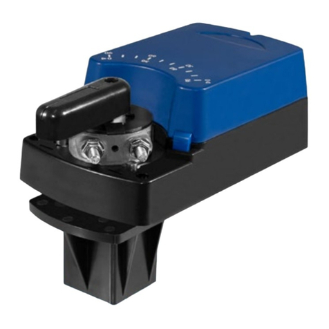
The device is an electromechanical linear drive. It performs linear movements.
2
3
1
Abb. 1 Patio linear drive
1 Fastening piston side (fork head)
2 Fastening housing (fork head)
3 Connection cable

35
Product description
EN
3.2 Technical data
All information in this section assumes an ambient temperature of 20°C.
3.2.1 Summary of the technical parameters
Technical data Patio
Rated voltage 24 V DC
Force, dynamic (N) 1.500
Force, static (N) 1.200
Stroke speed (mm/s) approx. 6
Stroke length (mm) 150
Rated current (A) approx. 2.3 1)
Output (W) 55
Duty cycle S3 15%
Type of protection IP 65
Temperature range -10°C - +60°C 2)
Limit switches Limit stop deactivation
Connecting rod Secured against rotation
Airborne noise emission > 60 dB (A) 3)
Weight up to 1.5 kg
Tab. 1 Technical parameters
1)
Option without deactivation: If there is a blockage, the control unit must switch off the current
supply within 10 seconds in order to avoid overloading the drive. Observe changeover time of
at least 2 seconds.
2)
Discrepancies in technical data possible.
3)
Noise level 60 dB(A) (with nominal power and without load in accordance with EN ISO 3745)

36
Product description
3.2.2 Information on the self-locking facility
WARNING
Danger of injury from loss of self-locking facility.
Crushing and battering possible.
• Provide safety equipment
WARNING
Possible damage to the device or the customer system from loss of self-locking
facility.
• Provide safety equipment.
There is a difference between dynamic and static self-locking in the devices. Dy-
namic self-locking is activated by movement and static self-locking is activated
when the machine stops. The self locking facility on the devices is dependent on
various factors, e.g.:
• Angle of elevation of the spindle and nut
• Surfaceroughnessoftheanksofthespindleandnut
• Running speed
• Lubricant
Theself-lockingfacilitycanbenegativelyinuencedbyanumberoffactors,
e.g.:
• Shocks and vibrations
• Loads
• Heating
A theoretical self-locking spindle does not provide absolute self-locking. For this
reason, the assumption of any warranty obligations relating to self-locking is
excluded.
Self-lockingisNOTforthepurposeoffulllinganysafety-relatedcriteria.
In order to minimise any further dangers, observe the duty of care that is normal
for technical products.

37
Installation
EN
4 Installation
WARNING
Danger of injury from weather influences.
The skin may suffer frostbite or burns.
• Wear personal protective equipment.
WARNING
Risk of injury from incorrectly dimensioned mountings.
Crushing and battering possible.
• Use only fastening materials that are suitable for the dimensions of the
mountings.
• The counter-mountings (provided by customer) must be designed at least for
the forces for which the device has been designed.
WARNING
Danger of injury from loss of support and holding function.
Crushing and battering possible.
• Pay attention to static loads.
WARNING
Damage to the device from installation outside or in damp rooms.
• The clamping units of the connecting cable must be designed with the requi-
red IP protection class.
• Iflaidoutdoors,cablesmustbettedwithadriploop.
WARNING
Damage to the device from radial and/or torsional forces.
• The device must be designed in such a way that no radial and/or torsional
forces can act on the device.
WARNING
Damage to the device from blocking of the piston rod.
• The linear pathway of the piston must be freely moveable at all times.
• The pivoting range of the device must be kept clear.

38
Installation
WARNING
Damage to the device from loss of support and holding function.
• Pay attention to static loads.
4.1 Installation and connection
WARNING
Damage to electric cables from to crushing or a tensile load.
• All electric cables must be laid in such a way as to avoid the risk of crushing
and exposure to tensile loads.
1. Fasten the device only by the fastening elements provided for this purpose.
These are located at the end of the housing and on the piston rod (see Fig.
1).
2. Connect the device to the electrical supply.

39
Installation
EN
4.2 Electrical connection
WARNING
Damage to the device due to faulty electrical connection.
• The device must be operated with the correct connection voltage (see type
plate).
WARNING
Damage to the device from the use of a non-fitting or unsuitable drive control
unit.
• The control unit must support all the options attached to the device.
• Connect all the marked cable conductors.
• Insulate unmarked cores/cables.
WARNING
Damage or destruction of the device due to faulty electrical connection.
• The device must not be operated without an overcurrent shut-off.
• The device must be shut off by an overcurrent shut-off when it reaches the
limit positions. The overcurrent shut-off is optionally available as an internal
or external model.
• The customer-provided power supply must be capable of making at least the
minimum amount of current available to each device (see section 4.2.2). If
this current is not supplied, the device cannot be shut off when it reaches the
limit positions.
• Ifacongurationofthedevicewithoutelectronicshasbeenselected,the
overcurrent shut-off must be implemented externally by the customer.
WARNING
Damage or destruction of the device through ingress of moisture in the connec-
tion cables.
• For devices with protection type IP 65, the customer-provided connection of
the cable ends or connectors must also have IP 65 protection.

40
Installation
Nocircuitdiagramsarelistedbelowonaccountofthemultitudeofconguration
possibilities.
The device must be connected in accordance with the circuit diagram included
with the delivery.
Please refer to the following pages or the circuit diagram enclosed with the deli-
very for connection of the option selected by you.
4.2.1 Parallel connection
Multiple devices can be connected in parallel.
However, in this case the devices will not behave synchronously.
4.2.2 Minimum current of customer-provided power supply for each de-
vice
Model of device Rated voltage 24 V DC
1500 N 4 A
Tab. 2 Minimum current
4.3 Mechanical limit positions
Factory setting:
The limit positions have been preset to the dimensions corresponding to the
strokelengthdenedintheorderconrmation.
The device does not have a limit switch to shut it off when it reaches the limit
positions.
Upon reaching the limit stops, the device must switch off by means of an over-
current safety device (see chapter „4.2 Electrical connection“).
Table of contents
Other elero Controllers manuals

elero
elero BoxControl Compact User manual

elero
elero ExitSafe 28 388.0001 User manual

elero
elero Compakt User manual

elero
elero Combio-915 JA User manual

elero
elero Insolis 4 User manual

elero
elero AstroTec 28 060.0001 User manual

elero
elero Vario 1 User manual

elero
elero MemoTec-868 User manual

elero
elero InDrive M30/1.6 RH Product guide

elero
elero Picolo 0 User manual
Popular Controllers manuals by other brands

Macurco
Macurco TracXP TXP-C20 instruction manual

meitav-tec
meitav-tec PYROBOX3/19 Installation and operating manual

OptoSigma
OptoSigma SHOT-102 user manual

HydroPoint
HydroPoint WeatherTRAK ET Pro3 Bidding Specifications

SMC Networks
SMC Networks LET-X11 Series Operation manual

Nordson
Nordson ValveMate 7197PCP-2K quick start guide