Elesa DD51-E User manual

DD51-E (GN 9054)*
DD51-E-RF (GN 9154)*
*(Product series valid only for Germany)
Electronic position indicators
OPERATING INSTRUCTIONS

2
EN
DD51-E
(GN 9054)
- DD51-E-RF
(GN 9154)
Models all rights reserved in accordance with the law. Always mention
the source when reproducing our drawings and photos.
Contents
1. Safety Instructions 4
1.1 Release Information 5
2. System description 6
2.1 Wireless devices network 7
3. Assembly 7
4. Symbols on the display 8
5. Key functions 8
6. Turning on the system 10
6.1 Turning off the system 10
7. Operating mode 10
7.1 Absolute / incremental measuring
mode selection 10
7.2 Measure unit selection 11
7.3 Setting the absolute reference 12
7.4 Direct programming of the absolute
reference value (source), of the
compensation value (offset), of the
reading after one revolution (step) 13
7.5 Targets 13
7.5.1 Reaching the target position 14
7.5.2 Display target mode
15
7.5.3 Target tolerance
15

3
DD51-E
(GN 9054)
- DD51-E-RF
(GN 9154)
EN
Models all rights reserved in accordance with the law. Always mention
the source when reproducing our drawings and photos.
7.6 RF version (DD51-E-RF) 15
7.6.1 Programming the network
parameter (nEtid) and the
channel parameter (nEtch) 15
7.6.2 Targets 16
8. Programming mode 16
8.1 Programming parameters
with numeric values
16
8.2 Device parameters
(in alphabetical order)
17
8.3 Main menu tree 18
8.4 Target menu tree 20
8.5 Parameter value 20
8.6 Additional features
21
8.6.1 Reset 21
8.6.2 Test LCD
21
8.6.3 Release version 21
8.6.4 Password 21
9. Battery replacement 21
10. Problem solving 22

4
EN
DD51-E
(GN 9054)
- DD51-E-RF
(GN 9154)
Models all rights reserved in accordance with the law. Always mention
the source when reproducing our drawings and photos.
1 Safety Instructions
The product has been designed and manufactured in
accordance with the current regulations. The product lea-
ves the factory ready for use and complies with the safety
standards.
To maintain the product in this state, it is necessary that it
is assembled and used properly, in the closest complian-
ce with this instruction manual and with the following spe-
cific safety precautions.
Ensure that the user has read and understood the in-
struction manual and in particular the chapter “Safety
Instructions”.
In addition to the instruction manual, all the rules of law
must be observed, in regard to accident prevention and
environmental protection.
This manual is intended as an indispensable supplement
to the existing documentation (catalogues, data sheets
and assembly instructions).
The use, without complying with the
descriptions / specific parameters, in
combination with systems / machines /
processes to be controlled, can lead to
a malfunction of the product, causing:
- health hazards,
- environmental hazards,
- damage to the product and to its proper functionality.
The device must not be used:
- in explosion hazard areas;
- in medical/life support areas and equipment.
Do not open the equipment and do not tamper with it!
Any tampering might have a negative impact on reliability
of the device and might be dangerous. Do not attempt
any repair. Return any defective equipment to the
manufacturer! Any violation of the integrity of the device
as delivered will cause the warranty loss.
Changes or modifications not expressly approved by the
party responsible for compliance could void the user’s
authority to operate the equipment.

5
DD51-E
(GN 9054)
- DD51-E-RF
(GN 9154)
EN
Models all rights reserved in accordance with the law. Always mention
the source when reproducing our drawings and photos.
Setup / Commissioning
In case of any malfunction (even in case of change in
operating conditions), the device must be switched
off immediately. Switch off power supply during any
installation work at the equipment. Installation and
commissioning are allowed by trained and authorised staff
only. After correct setup and commissioning, the device is
ready for operation.
Maintenance / Repair
Switch off the power supply of the equipment before any
action. Maintenance should be performed by trained and
authorised staff only.
Do not open or modify the case of the indicator. Tampering
with this product may endanger the correctness and
accuracy of its operation.
In case of malfunction, do not attempt any repair to the
units and contact Elesa sales office.
1.1 Release Information
Even if almost all the functionalities are the same as in the
previous releases, the manual deals with devices with
release higher than 5.01.00 (see 8.5.3).
NOTE: This equipment has been tested and found
to comply with the limits for a Class A digital device,
pursuant to part 15 of the FCC Rules. These limits are
designed to provide reasonable protection against
harmful interference when the equipment is operated in
a commercial environment. This equipment generates,
uses, and can radiate radio frequency energy and,
if not installed and used in accordance with the
instruction manual, may cause harmful interference to
radio communications. Operation of this equipment in
a residential area is likely to cause harmful interference
in which case the user will be required to correct the
interference at his own expense.

6
EN
DD51-E
(GN 9054)
- DD51-E-RF
(GN 9154)
Models all rights reserved in accordance with the law. Always mention
the source when reproducing our drawings and photos.
2 System description
The electronic position indicators DD51-E, with battery
power supply, can be used on passing through shafts
in any position to provide the reading of the absolute or
incremental positioning of a machine component.
Mechanical and electrical characteristics
Power supply Lithium battery CR2450 3.0 V
Battery life Up to 5 years
(3 years for RF version)
Display 5-digit LCD of 8 mm height
and special characters
Reading scale -19999; 99999
Number of decimal digits programmable (1)
Unit of measure mm, inches, degrees
programmable (1)
Rotation max. speed 300/600/1000 r.p.m. (2)
programmable (1)
Precision 10.000 impulses/revolution
Protection level IP65 or IP67
Working temperature 0 °C ÷ +50 °C
Storage temperature -20 °C ÷ +60 °C
Relative humidity max. 95% a 25 °C
without condensation
Environment indoor use
Altitude up to 2000 m
(1) See cap. 8.1
(2) Default: 600 r.p.m.
WARNINGS!
Higher rotation speeds to 600 r.p.m. can be maintained for
short periods of time.
The value of the max speed affects the battery life.

7
DD51-E
(GN 9054)
- DD51-E-RF
(GN 9154)
EN
Models all rights reserved in accordance with the law. Always mention
the source when reproducing our drawings and photos.
2.1 Wireless devices network
The electronic position indicators DD51-E-RF is compatible
with Elesa wireless network which allows electronic position
indicators to communicate with a PLC via radio.
Elesa wireless network is made by the following components:
- One control unit UC-RF
- Max 36 device as DD51-E-RF, DD52R-E-RF or MPI-R10-RF
The control unit UC-RF is provided with a standard interface
for the most common industrial busses to be connected to
the PLC and allows the information transmission between
the PLC and the electronic position indicators DD51-E-RF.
The control unit UC-RF exchanges information with
the electronic position indicators DD51-E-RF via radio
frequency and allows the setting of the target position and
the control of the current position of each indicator, directly
from the PLC.
WARNINGS! Read the control unit UC-RF instructions
for more details regarding its configuration.
3 Assembly
1. Drill a Ø 6x10 mm hole in the body of the machine with
a 22 mm centre distance from the shaft to fit the rear
referring pin.
2. Fit the indicator onto the spindle and make sure that
the referring pin fit the hole.
3. Clamp the boss to the
spindle by tightening the
grub screw with hexagon
socket and cup end,
according to UNI 5929-85.
Target positions
Current positions
PLC
8
EN
DD51-E
(GN 9054)
- DD51-E-RF
(GN 9154)
Models all rights reserved in accordance with the law. Always mention
the source when reproducing our drawings and photos.
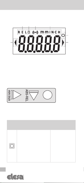
4 Symbols on the display
1. Relative mode
2. Low battey level
3. RF connection
4. Unit of measure (mm / inch)
5. Unit of measure (degrees)
6. Target position indications
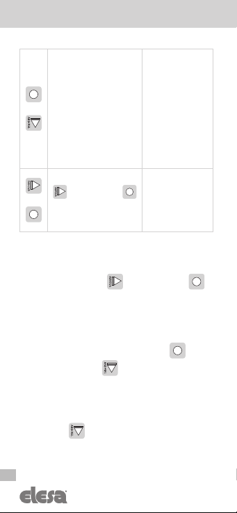
5 Key functions
WARNINGS!
The key icons are conventionally shown with the default
display rotation set to 180.
Key Operating
mode
Programming
mode
Press for 3 sec to enter the
programming mode.
When the target is active,
press the key to show the
actual position or the target
position on the display
accordance to the setting
of the menu
____0
see
cap. 7.5.2
Parameter selection /
Confirm of parameter
change
123
5
4
66

9
DD51-E
(GN 9054)
- DD51-E-RF
(GN 9154)
EN
Models all rights reserved in accordance with the law. Always mention
the source when reproducing our drawings and photos.
Select the:
Absolute measuring mode
Incremental measuring mode
It is possible to choose one
of the following options (see
the
__0__
voice of the
menu – cap. 8.3):
ArCLr
[DEFAULT]:
switching from
ABS
to
REL
the counter is set to zero.
Ar
: switching from
ABS
to
REL
the counter is not
set to zero.
OFF
: the key is not assigned
to any function in the
operating mode.
Digit increase /
programming
mode exit
Press the key to select the
unit of measure needed.The
options available are: mm,
inch and degrees.
It is possible to choose one
of the following options (see
the
0____
voice of the
menu – cap. 8.3):
ALL
[DEFAULT]: selectable
units of measure: mm, inch, D
nodEG
: selectable units of
measure: mm, inch
OFF
: the key does not allow
the unit of measure conversion
Scroll for parameters /
digit selection
+
Programmable with one of
the following options (see
the
0___0
voice of the
menu – cap. 8.3):
P_OrG
[DEFAULT]: show
and set the
OriGin
parameter
P_StP
: show and set the
StEP
parameter
P_OFS
: show and set the
OFFS
parameters
OFF
: the key combination is
not assigned to any function
in the operating mode.
N/A
10
EN
DD51-E
(GN 9054)
- DD51-E-RF
(GN 9154)
Models all rights reserved in accordance with the law. Always mention
the source when reproducing our drawings and photos.
+
Programmable with one of
the following options (see
the
__0_0
voice of the
menu – cap. 8.3):
L_OrG
[DEFAULT]: the
key combination sets the
absolute value to the sum of
the parameters Origin and
Offset.
OFF
: the key combination is
not assigned to any function
in the operating mode.
N/A
>
To turn on the indicator, hold
then press the key
After the start-up sequence
the indicator will be ready to
be used (see cap. 6)
N/A
6 Turning on the system
After reading and understanding the section “Safety
Instructions”, proceed by switching on the indicator.
Turn the indicator on hold then press the key .
The display will light up and the indicator will be ready
to be used.
6.1 Turning off the system (only for storage)
To turn the system off enter the programming mode, select
the
rESEt
parameter then press the key . At this
point, press the button for 5 seconds; the display
will turn off and the indicator will go into into sleep mode.
7 Operating mode
7.1 Absolute / incremental measuring mode selection
Press the key to select the absolute or incremental
measuring mode.
If the incremental measuring mode is selected, the symbol
REL
is shown on the display.

11
DD51-E
(GN 9054)
- DD51-E-RF
(GN 9154)
EN
Models all rights reserved in accordance with the law. Always mention
the source when reproducing our drawings and photos.
If the absolute measuring mode is selected no symbol is
shown on the display.
It is possible to change the key function
by chosing one of the available options
in the voice menu
__0__
The available options are:
-
ArCLr
(default): passing from
ABS
to
REL
the
counter is set to zero.
-
Ar
: passing from
ABS
to
REL
the counter is not set to
zero. In this case, the counter is set to zero by pressing
+ .
-
OFF
: the key is disabled and does not allow
changing the selected measuring mode.
To program the parameters listed above, see cap. 8.
7.2 Measure unit selection
Press the key to select the unit of measure needed.
The options available are millimeters, inches and degrees.
The measuring mode selected is shown on the display by
the symbols:
-
mm
: millimeters -
INCH
: inches -
D
: degrees
It is possible to change the key function
by chosing one of the available options
in the voice menu
0____
The available options are:
-
ALL
(default): units of measure that can be selected:
mm, inch, degree
-
nodEG
: units of measure that can be selected: mm,
inch
-
OFF
: the key is disabled and does not allow changing
the selected measuring mode.
To program the parameters listed above, see cap. 8.
0____
__0__
12
EN
DD51-E
(GN 9054)
- DD51-E-RF
(GN 9154)
Models all rights reserved in accordance with the law. Always mention
the source when reproducing our drawings and photos.
7.3 Setting the absolute reference
After having selected the absolute measuring mode and
stopped the shaft in the starting position or in the reference
position, press the key combination +to set the
absolute value to the sum of the values of the parameters
OrG
(absolute reference value) and the selected
OFFS
(compensation value).
The value of compensation (offset) allows you to adjust
the value shown on the display in such a way that takes
into account, for example the wear or the tool change. The
system allows to store up to 10 values of compensation.
By pressing the key combination +, the screen
shows the last compensation value used (eg
OFS 0
).
Choose the desired compensation value by pressing the
key , and then press the key to confirm.
The screen will display the absolute value equal to the
sum of the values of the parameters
ORG
and
OFFS
.
To program the offset values, see parameter
OFFS
of
cap. 8.
It is possible to change the key function
by chosing one of the available options
in the voice menu
__0_0
The available options are:
-
L_OrG
: the key combination +allow to
choose an offset compensation and set the origin value;
-
OFF
: the keys combination +is not
associated to any function in the operating mode.
To program the parameters listed above, see cap. 8.
__0_0
13
DD51-E
(GN 9054)
- DD51-E-RF
(GN 9154)
EN
Models all rights reserved in accordance with the law. Always mention
the source when reproducing our drawings and photos.
7.4 Direct programming of the absolute reference value
(origin), of the compensation value (offset), of the
reading after one revolution (step)
The function of the keys combination +allows
direct access to the programming of one of the following
parameters: Origin, Step or Offset.
It is possible to change the key function
by chosing one of the available options
in the voice menu
0___0
The available options are:
-
P_OrG
: direct programming of the absolute reference
value (OrG parameter)
-
P_StP
: direct programming of the reading after one
revolution (StEP parameter)
-
P_OFS
: direct programming of the compensation
value (OFFS parameter)
-
OFF
: the keys combination +is not linked
to any function in the operating mode
For programming the parameters listed above see
parameter
0___0
of cap. 8.3.
7.5 Targets
The electronic position indicators DD51-E allows the
set up of 32 target positions to store relevant machine
configuration setting.
To program the targets:
- select
tArGE
in the main menu (see cap. 8.3)
- select
PrOGt
(see cap. 8.4)
- select the memory location (
PtG01
to
PtG32
) by
using the keys
- press the key to select.
- follow the instructions in cap. 8.1 to set the value.
0___0
14
EN
DD51-E
(GN 9054)
- DD51-E-RF
(GN 9154)
Models all rights reserved in accordance with the law. Always mention
the source when reproducing our drawings and photos.
To load a target:
- select
tArGE
in the main menu (see cap. 8.3)
- select
LOAdt
(see cap. 8.4)
- select the target value (
LtG01
to
LtG32
) by using the
keys
- press the key to select
- the value of the selected target is shown
- press again to confirm or press to go back to
the target selection list.
WARNINGS!
When a target is loaded the mesure unit cannot be changed.
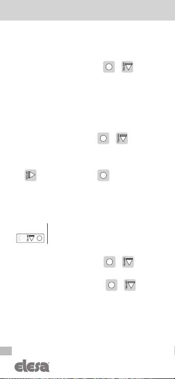
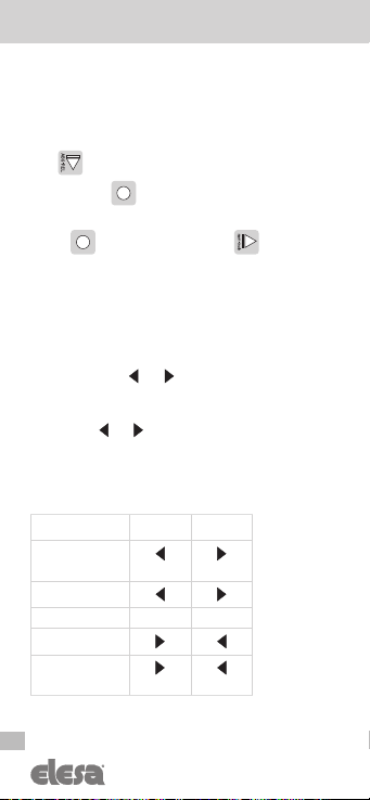
7.5.1 Reaching the target position
If a target is selected, the device suggests the shaft
rotation direction in order to reach the target position by
using the symbols and
It is possible to set the tolerance of the target by means of
the
PtOLL
parameter (see cap. 8)
The symbols and works depending from the
dir
and
PtOLL
parameters, as shown below:
T = set target
M = measured value
Toll = tolerance (see Ptoll)
dir –o dir o--
M < T - Toll (blinking) (blinking)
T - Toll ≤ M < T
M = T
T < M ≤ T + Toll
M > T + Toll (blinking) (blinking)
If a target is selected it is possible to cancel it by entering
the programming mode and by selecting the
StoPt
option.

15
DD51-E
(GN 9054)
- DD51-E-RF
(GN 9154)
EN
Models all rights reserved in accordance with the law. Always mention
the source when reproducing our drawings and photos.
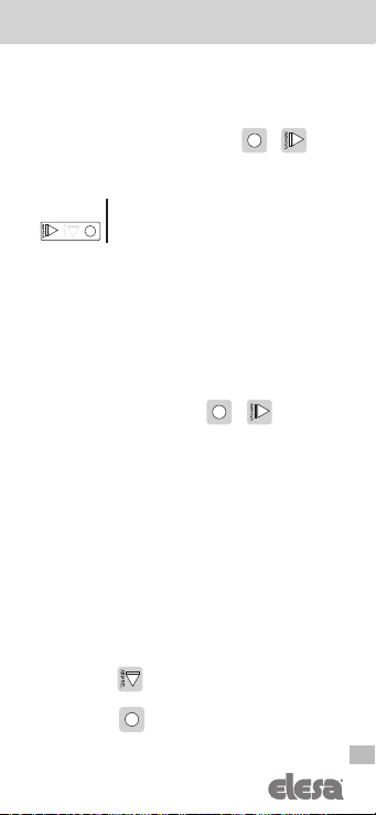
7.5.2 Display target mode
The
____0
voice menu (see cap. 8.3) allows the user
to choose one of the following target modes listed below:
-
dtArG
(default): when a target is loaded, the display
shows the actual absolute position and the indication
to reach the target, as already explained in cap. 7.5.1.
Pressing the key the set target position is shown.
-
dtoGo
: when a target is loaded, the display shows the
distance to the set target and the indication to reach the
target as already explained in cap. 7.5.1. If the target is
not reached, the display blinks. By pressing the key ,
the display shows the actual absolute position.
-
OFF
: the key is not associated to any function in the
operating mode.
7.5.3 Target tolerance
Set the value of
Ptoll
parameter to define the tolerance
allowed for the target (see cap. 8 for details).
7.6 RF version (DD51-E-RF)
7.6.1 Programming the network parameter (nEtid) and
the channel parameter (nEtch)
The radio network of the system is defined by the following
two parameters:
nEt
id
: id 00/99 (NetID = 03 is reserved and it is not possible
to be used)
nEt ch
: ch 01/36
These parameters can be configured in the radio menu of
the indicator (see cap. 8) and they must be set according
to the PLC recipe in order to guarantee a perfect
communication between the control unit UC-RF and the
electronic position indicator DD51-E-RF.
Warning
For the DD51R-E-RF with firmware release equal to 5.1 or
higher, channel 1 is equivalent to channel 4 of the previous
version. Consider it in case of use of the old system with
UC-RF with fw release lower than 5.1

16
EN
DD51-E
(GN 9054)
- DD51-E-RF
(GN 9154)
Models all rights reserved in accordance with the law. Always mention
the source when reproducing our drawings and photos.
7.6.2 Targets
Using the electronic position indicators DD51-E-RF,
the target positions can be sent from the PLC to the
indicators through the control unit. When a target is set,
the behaviour is the same as described in cap. 7.5.
8 Programming mode
Press the key for 3 seconds to enter the programming
mode. Depending on the setting of
PASS
parameter (see
cap. 8.6.4), the system may require to enter by using a
password.
Press the key to scroll through the list of parameters
and select the required one by pressing .
Press the key to exit the programming mode. The
programming mode is automatically dropped after 30
seconds of inactivity.
8.1 Programming parameters with numeric values
Press the key to increase the flashing digit.
Press the key to select the next digit.
Press the key to confirm the value and go back to
the list of parameters.
The numeric values of the parameters
must be inserted taking into account
the selected unit of measure.
When a parameter is changed from its stored value, by
confirming it, the display shows the message
CHAnG
.
When exiting in the programming mode, the parameters
are stored in the internal memory. If a parameter is
changed, the display shows the message
StorE

17
DD51-E
(GN 9054)
- DD51-E-RF
(GN 9154)
EN
Models all rights reserved in accordance with the law. Always mention
the source when reproducing our drawings and photos.
8.2 Device parameters (in alphabetical order)
Parameter Description Available options Standard
value
dir
Measurement
direction
Set direction
of the positive
axis
--o
counterclockwise
rotation to increment
the measure
o--
clockwise rotation
to increment the measure
--o
diSP
Display
orientation
0°
180°
180°
OFFS
Offset Value See cap. 8.5
The system allows
to store up to 10
compensation values:
OFS 0
...
OFS 9
0
OrG
Reference
value
displayed at
the starting
point
See cap. 8.5
0.0
Ptoll
Tolerance
of target
position
mm
: 0.01 ÷ 9.99
inches
: 0.001 ÷ 0.393
degrees
: 0.01 ÷ 9.99
The parameter value
depends on the unit of
measure selected.
mm:
0.10
inches:
0.004
Degree:
0.10
Radio
Wireless
transmission
parameters
nEt id: id00 ÷ id99
nEt ch: ch01 ÷ ch36
id00
ch01
rES
The parameter
allows to defin
the resolution
of the measure
mm:
1
;
0.1
;
0.01
inches:
1
;
0.1
;
0.01
;
0.001
degrees:
1
;
0.1
;
0.01
mm:
0.1
inches:
0.01
degrees:
1
SPEEd
Set the
maximum
speed in rpm
that can be
correctly read
300
;
600
;
1000 600

18
EN
DD51-E
(GN 9054)
- DD51-E-RF
(GN 9154)
Models all rights reserved in accordance with the law. Always mention
the source when reproducing our drawings and photos.
Parameter Description Available options Standard
value
StEP
Reading
after one
revolution
0.01
;
100.00
001.00
_ _ _ _ 0
“
t_Sho
”
Display
visualization
during target
mode
d_toG0
: during the
positioning, the display
shows the distance
from the target. Press
the key to see the
actual position of the
indicator.
d_tArG
: during the
positioning, the display
show the actual position,
press the key to
see the target position
to reach.
d_toG0
tArGe
Target options See cap. 8.5
0.0
8.3 Main menu tree
StEP 0.01 ÷ 100.00
OrG
See Cap. 8.5
dir --o
o--
OFFS
OFS 0
...
OFS 9
rES
See Cap. 8.5
See Cap. 8.5
mm
1
0.1
0.01
Inch
1
0.1
0.01
0.001
deg
1
0.1
0.01
Scrolling direction

19
DD51-E
(GN 9054)
- DD51-E-RF
(GN 9154)
EN
Models all rights reserved in accordance with the law. Always mention
the source when reproducing our drawings and photos.
0____ OFF
ALL
nodEG
__0_0 L_OrG
OFF
0___0
OFF
P_StP
P_OrG
P_OFS
__0__ ArCLr
OFF
Ar
Scrolling direction
____0 OFF
dtArG
dtoGo
PASS
See Cap. 8.6.4
rESEt
See Cap. 8.6.1
LcdtS
See Cap. 8.6.2
Fj.i.bb
Release Version (see cap. 8.6.3)
* See key definition 7
*
*
*
*
*
diSP 0°
180°
rAdio
nEt id
nEt ch
00
...
99
ch 01
...
ch 36
PtoLL
0.01 ÷ 9.99
0.001 ÷ 0.393
mm
Inch
tArGE
See Cap. 8.4
SPEEd
300
600
1000

20
EN
DD51-E
(GN 9054)
- DD51-E-RF
(GN 9154)
Models all rights reserved in accordance with the law. Always mention
the source when reproducing our drawings and photos.
StoP_t
*
LOAd_t
LtG 01
...
LtG 32
PrOG_t
PtG 01
...
See Cap. 8.5
PtG 32
See Cap. 8.5
Scrolling direction
* Displayed only if a target position is set
mm
-9999
÷
9999
Inch deg
-999.9
÷
999.9
-99.99
÷
99.99
-393.7
÷
393.7
-99.99
÷
99.99
-0393
÷
0393
-999.9
÷
999.9
-99.99
÷
99.99
-9999
÷
9999
-9.999
÷
9.999
rES
0 .1
0.01
1
0.001
8.4 Target menu tree
8.5 Parameter value
The parameter value depends on the unit of measure and
resolution set.
The value may change according to the resolutions of mm
and inch.
Es.
If
rES
mm =
1
and
rES
inch =
0.01
The max parameter in mm is
-2539 ÷ 2539
because
if we convert the value in inch 2539 / 25.4 =
99.96
which is the max value visible on the display with the res
inch =
0.01
In case the parameter is
2540
it is not possible to show
the converted value because 2540 / 25.4 =
100.00
Other manuals for DD51-E
7
This manual suits for next models
1
Table of contents
Other Elesa Measuring Instrument manuals


