Elived YD1008 User manual

W
H
Arm and Wall Plate
01 x1 02 x1
Monitor Plate Extenders
03 x4
Step 3-1 Select monitor plate configuration Step 3-2 Assemble monitor plate and extenders
Select the configuration A , B , C, or D to use based on the measurement from step 2.
If your TV hole pattern is greater
than 100x100mm, attach
extenders [03] to monitor plate
[02]using Nut [C] and Bolt [D] .
for VESA hole pattern:
75x75mm, 100x100mm.
A
VESA Pattern
(WxH) Configuration VESA Pattern
(WxH) Configuration
75mm x 75mm A C
100mm x 100mm A D
B C
100mm x 200mm
150mm x 150mm
200mm x 100mm
200mm x 200mm
CD
M-B
M-A
Use the shorter
screws
M-B
M-C
M-E
Not for M8 screws
M-B
M-A
Use the
longer screws
M-B
M-E
M-FM-D
Step 3-3
Attach the brackets
(a) For Flat Back
(b) For Round Back / Extra Space
75mm
100mm
75mm
100mm
200mm
200mm
150mm
150mm
200mm
200mm
100mm
100mm
02
B
D
C
03
Top of TV
Top of TV
ST6.3 x 60mm
Lag Bolts
x2 x1
B C DA
Open-end wrench Nuts Bolts
x4 x4
03
02
Max:200x200mm /8x8"
Min:75x75mm /3x3"
14"~40"
(V4)
YD1008
INSTALLATION INSTRUCTION
Bubble level X1
Hardware Included
Hardware (Wall /Product)
Philips Screws
M6 x 15mm
M6 x 30mm
Philips Screws
M4 x 12mm
M4 x 30mm
Washers
Ø6mm
M4-5-6
Spacers
L10mm
x4
x4 x4x4
Philips Screws
M8 x 25mm
x4 x4 x4
Spacers
L5mm
x4
TV Screws / Washers
M-A M-B M-C M-D M-E M-F
Measure and note the width and the height
of the square or rectangle formed from the
VESA holes pattern .
Step 2 Mesure your TV pattern
2M2M
Step 1-1 Select TV screw diameter
Thread screws by hand into the threaded holes on the back of your TV to select which screw
diameter fits your TV.
M6M4 M8
Correct Correct
Too Long
Too Short
Step 1-2 Select TV screw length
75mm ≈3in.
100mm ≈4in.
150mm ≈6in.
200mm ≈8in.
for VESA hole pattern:
150x150mm, 200x200mm
for VESA hole pattern:
100x200mm for VESA hole pattern:
200x100mm
BD
C
Max:
(20KG)
44LBS
Safety Caution
Must Check Before Getting Started
Installation Tools (Not Included)
Band
Tape
2M
Socket
Wrench
ScrewdriverPencil Electrodrill
Stud
Finder
HammerAwl Wood
Drill Bit
Masonry
Drill Bit
Wood Stud Installation Concrete Installation
1/2"
(13mm)
3/8"
(10mm)
5/32"
(4mm)
MAX:200mm/8"
MAX:
200mm/8"
Min. 8"
(203mm)
Solid concrete wall
CAUTION: DO NOT install into drywall alone.
<16mm(5/8")
Drywall with wood studs
Max:
(20KG)
44LBS
No!
No!
When attaching brackets to the flat screen, be careful not to over tighten screws and
be sure that screws do not bottom out in the mounting holes.
If you have any questions, please contact us.
Please read this instruction carefully before installation.
If you do not understand these instructions or have doubts about the safety of the installation, assembly
or use of this product, please contact us.
●This product is designed for use in wood stud and solid concrete wall.
- DO NOT install into drywall alone.
●The wall must be capable of supporting five times the weight of the TV and mount combined.
● Do not apply this product to any purpose not indicated by ELIVED.
● Incorrect installation may result in product damage or body injury. ELIVED shall bear no responsibility
for any damage or injury resulted from incorrect installation, incorrect assembly or misuse.
WARNING: This product contains small items that could be a choking hazard if swallowed.
Before starting assembly, verify all parts are included and undamaged. For parts shortage or damage,
please contact us.
2
1
5
4
3
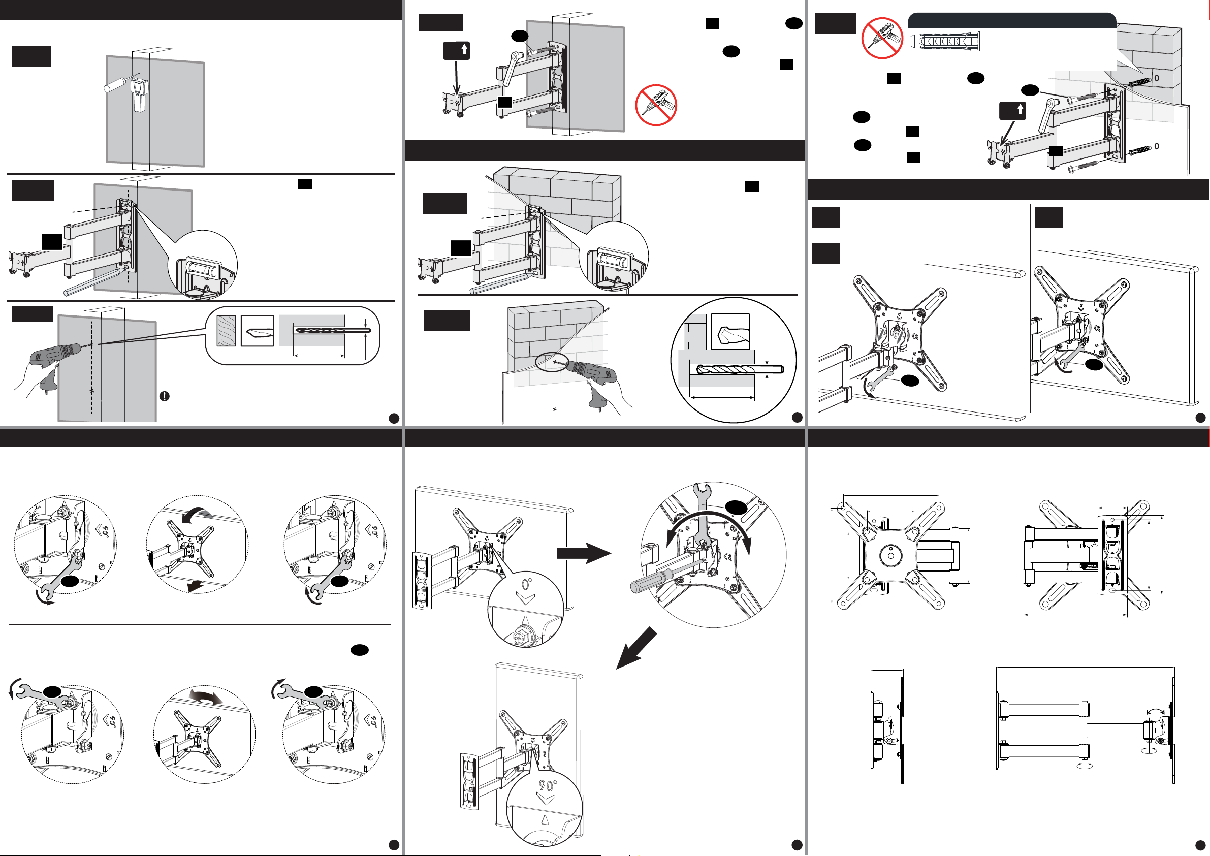
Step 4A Wall plate installation (wood stud)
4A-1
4A-2
Locate your studs. Verify and
mark the center of the stud by
finding the stud edges using an
awl, a thin nail, or an
edge-to-edge stud finder.
Position the wall plate at your desired height
and line up the holes with your stud center line.
Level the wall plate and mark the pilot hole
locations x2.
01
4A-3
Lift and hang TV assembly onto arm and wall
plate.
Secure the monitor plate to the arm
and wall plate with the removed
screws and washers from the
previous step.
Tilting angle adjustment (+3° / -10°)
Leveling adjustment
Loosen the screws Tighten the screws
Tilt the TV
+3 /-10°
Loosen the screw Tighten the screw
Level the TV
Adjust TV to your desired angle then fasten tilting screws with open-end wrench.
If needed, TV can be leveled via adjusting the screw with the open-end wrench or
screwdriver.
Adjustments
B
B
B
B
B
Switch screen horizontally and vertically
If needed, the TV can be rotated ±90 degrees for switching screen between horizontally and vertically.
Use the open-end wrench to
loosen and tighten this screw if
necessary.
Screwdriver can be used for
adjusting the screw to secure the
TV direction if need.
No need to adjust this screw if
the mount can hold the TV at your
desired direction via the default
factory setting.
Horizontal screen
±90°
Vertical screen
B
0° up
90° up
Product dimensions:
5-1
5-2
5-3
+3°/-10°
380mm
68mm
200mm
100mm
200mm
115.8mm
100mm
210mm
143mm
59mm
164mm
Drill pilot holes using a 5/32 in. (4 mm) diameter drill bit.
IMPORTANT:
Pilot holes must be drilled to a depth
of 2 3/4 in (70 mm). Be sure to drill into the center of thestud.
5/32 in
Ø4 mm
4A-4 01 A
A
Install wall plate using lag bolts
with Socket Wrench, NO Electrodrill.
Tighten the lag bolts until they are
pulled firmly against the wall plate .
01
01
Position the wall plate at
your desired height , level
the wall plate and mark the
pilot hole locations x2.
4B-1
A
B
Step 4B Wall plate installation (concrete or brick)
Step 5 Lift and hang TV with brackets onto wall bracket
Contact us to have these additional pieces
shipped directly to you.
Concrete wall anchor 2pcs (NOT INCLUDED)
Ø10*61mm
01
A
A
A
01
01
Install wall plate using lag bolts
and anchors (not included) with Socket
Wrench, NO Electrodrill. Tighten the
lag bolts until they are pulled firmly
against the wall plate . Tighten the
lag bolts until they are pulled firmly
against the wall plate .
01 Level 01
01
A
4B-2
Drill pilot holes
2.75in (70 mm)
Ø 10 mm
Ø 10 mm
3/8in
01
Remove 2 preassembled screws and washers
before hang TV on to the wall bracket, and
save them for using to next step.
Loosen
Tighten
B
UP
UP
2
2
Level
4B-3
No!
No!
2.75in (70 mm)
180°
180°
7
68
11
10
9
Other manuals for YD1008
1
Other Elived TV Mount manuals

Elived
Elived YD1006 User manual

Elived
Elived EV014 User manual

Elived
Elived EV018 User manual

Elived
Elived YD1004-A User manual

Elived
Elived EV011 User manual

Elived
Elived YD3004 User manual

Elived
Elived YD1003-A User manual

Elived
Elived EV025 User manual

Elived
Elived YD1007 User manual

Elived
Elived YD1007 User manual


