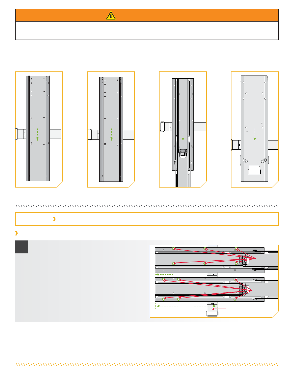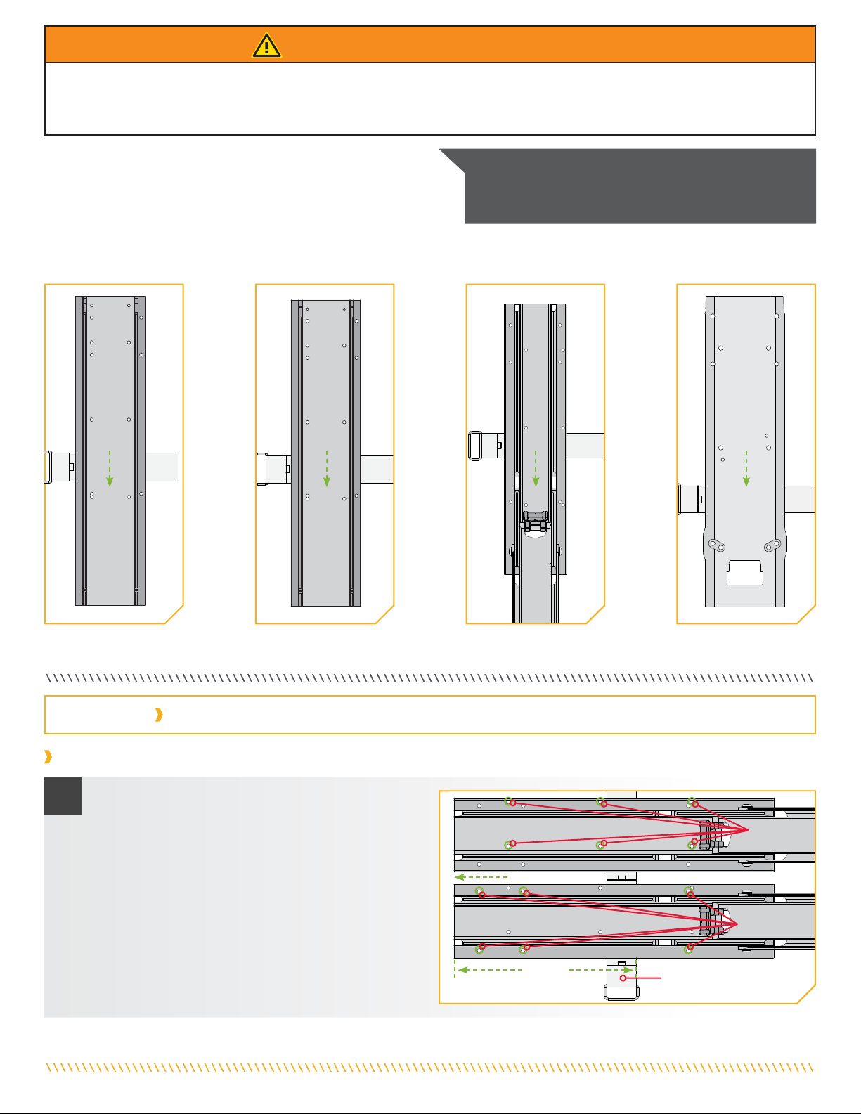
b. Trois des trous de montage à utiliser sont situés sous
le support du moteur. Selon le boulonnage désiré, au
moins un côté du support du moteur devra être retiré
pour l’accès à ces trous.
c. À l’aide d’un tournevis nº 2, retirez temporairement les
trois vis cruciformes qui fixent le support du moteur
à l’extrusion de la plaque avant. Retirez le support du
moteur afin d'exposer les trous de montage du moteur.
Repose-moteurRepose-moteur
VisVis
cruciformescruciformes ExtrusionExtrusion
de la plaquede la plaque
avantavant
Trous de montageTrous de montage
22c
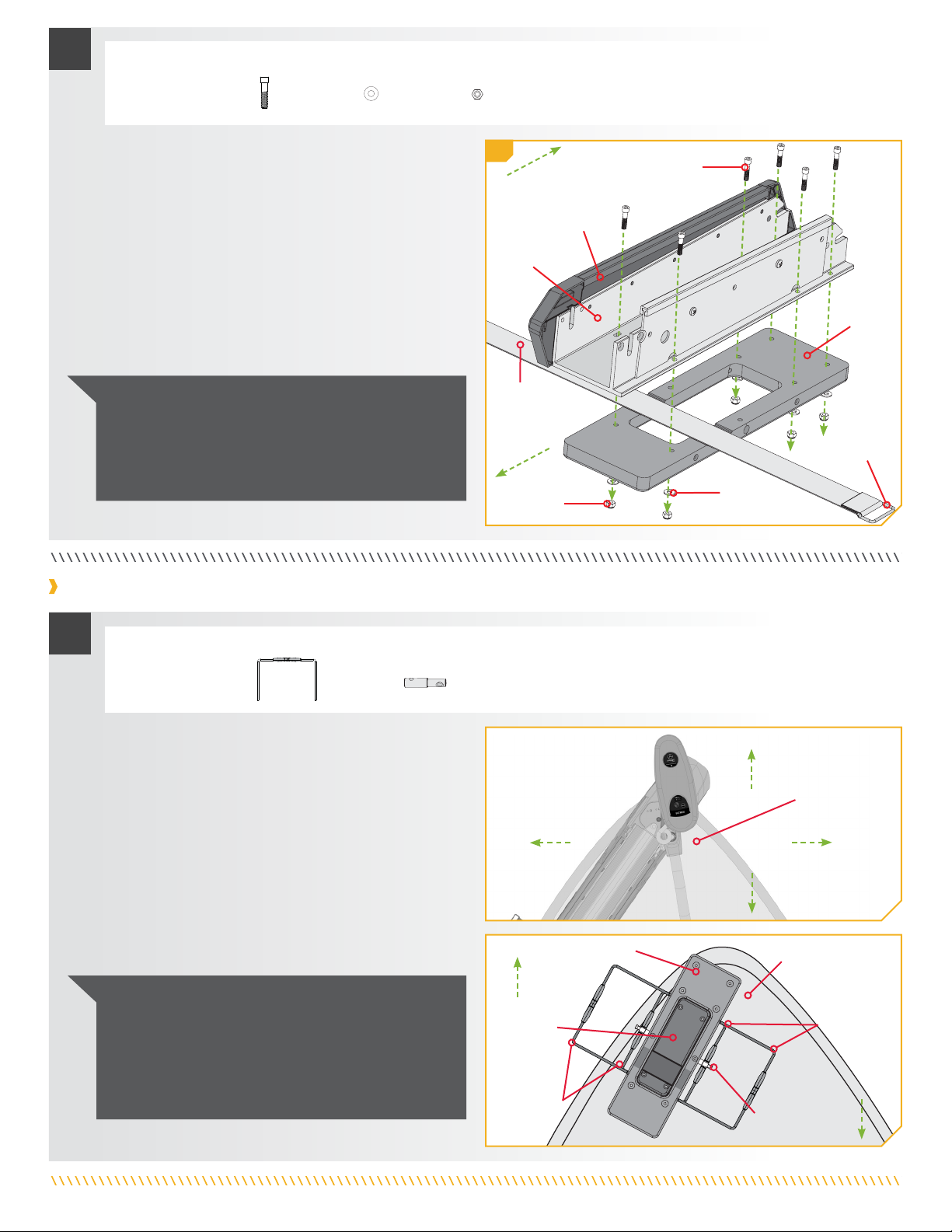
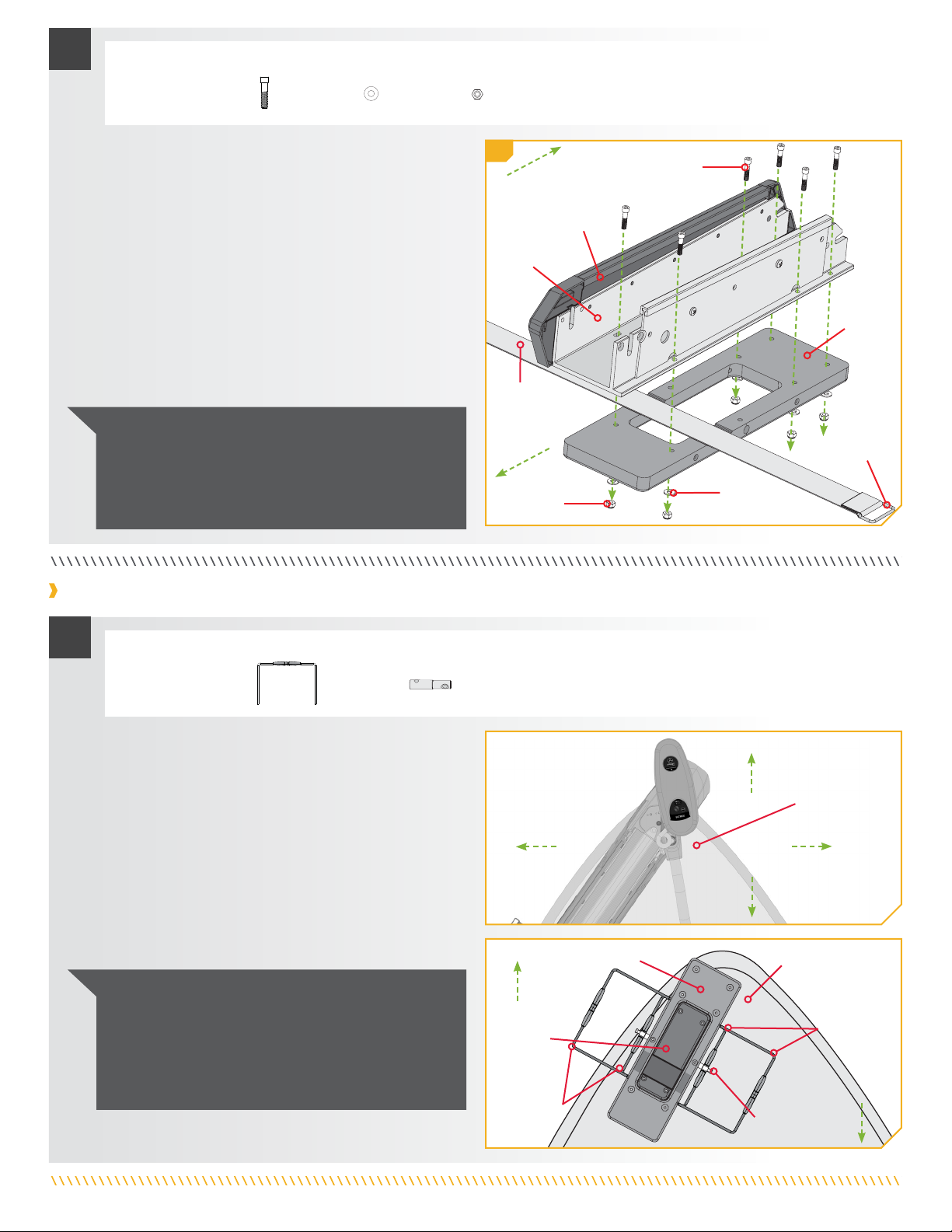
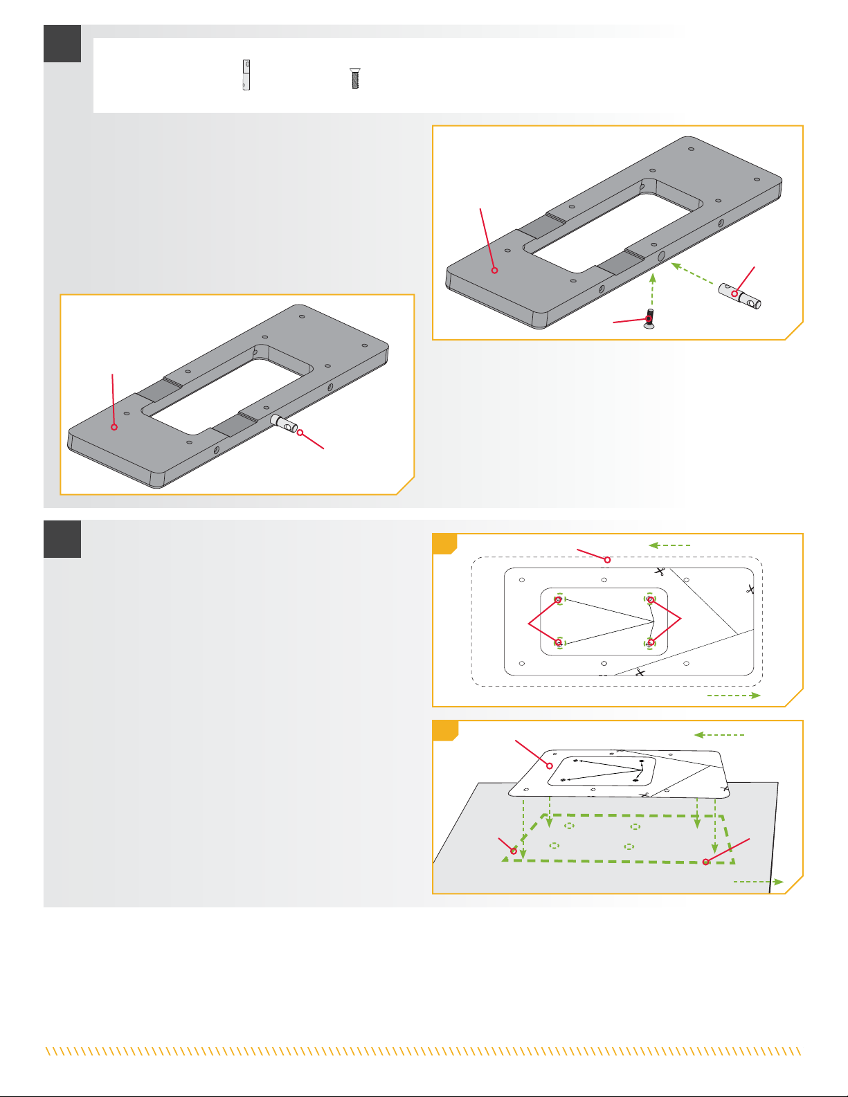
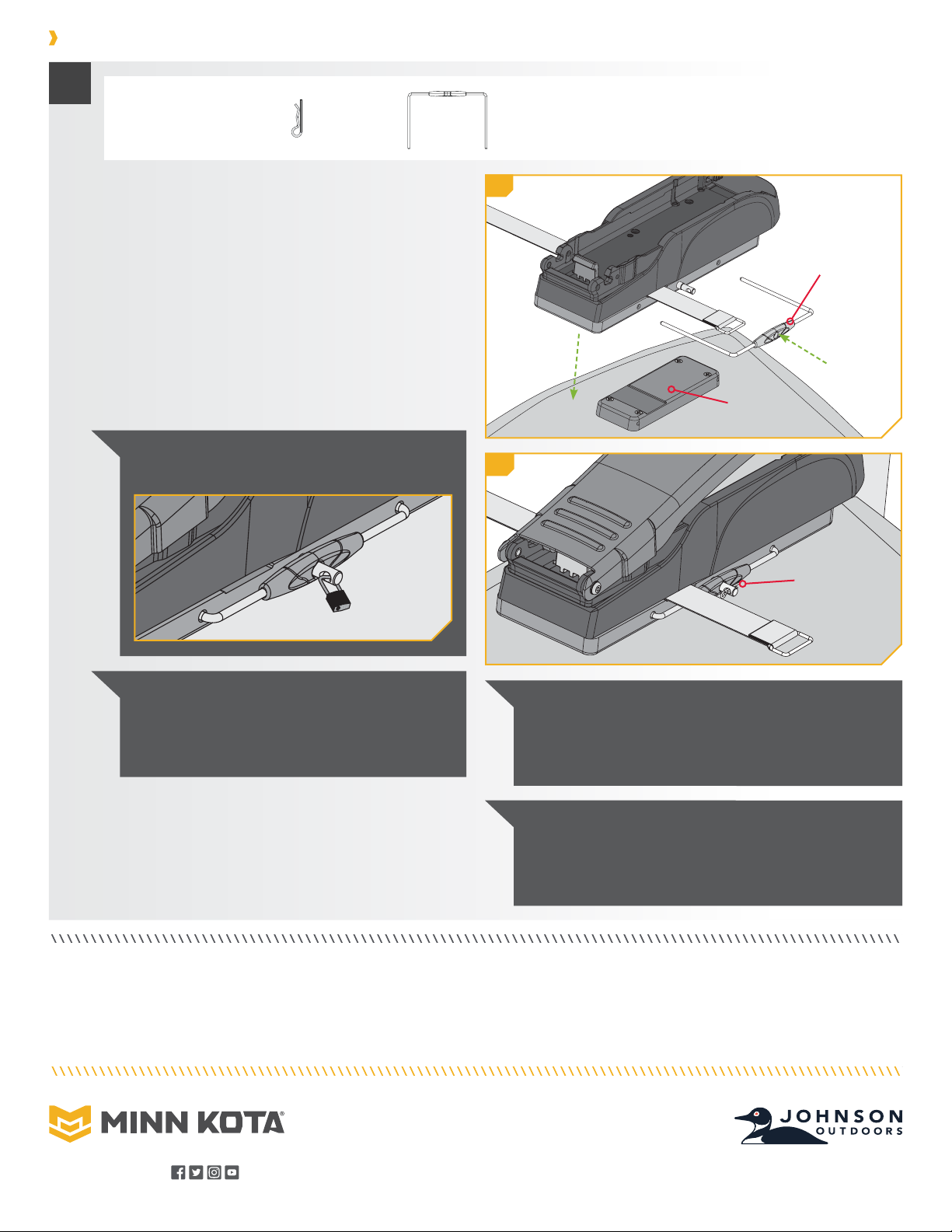
d. Placez la sangle de stabilisation (si incluse avec votre
moteur) dans la rainure sur la plaque externe
(article nº 4). Orientez la boucle du côté désiré.
La rainure devrait être du côté le plus en-bord sur
l’installation finale.
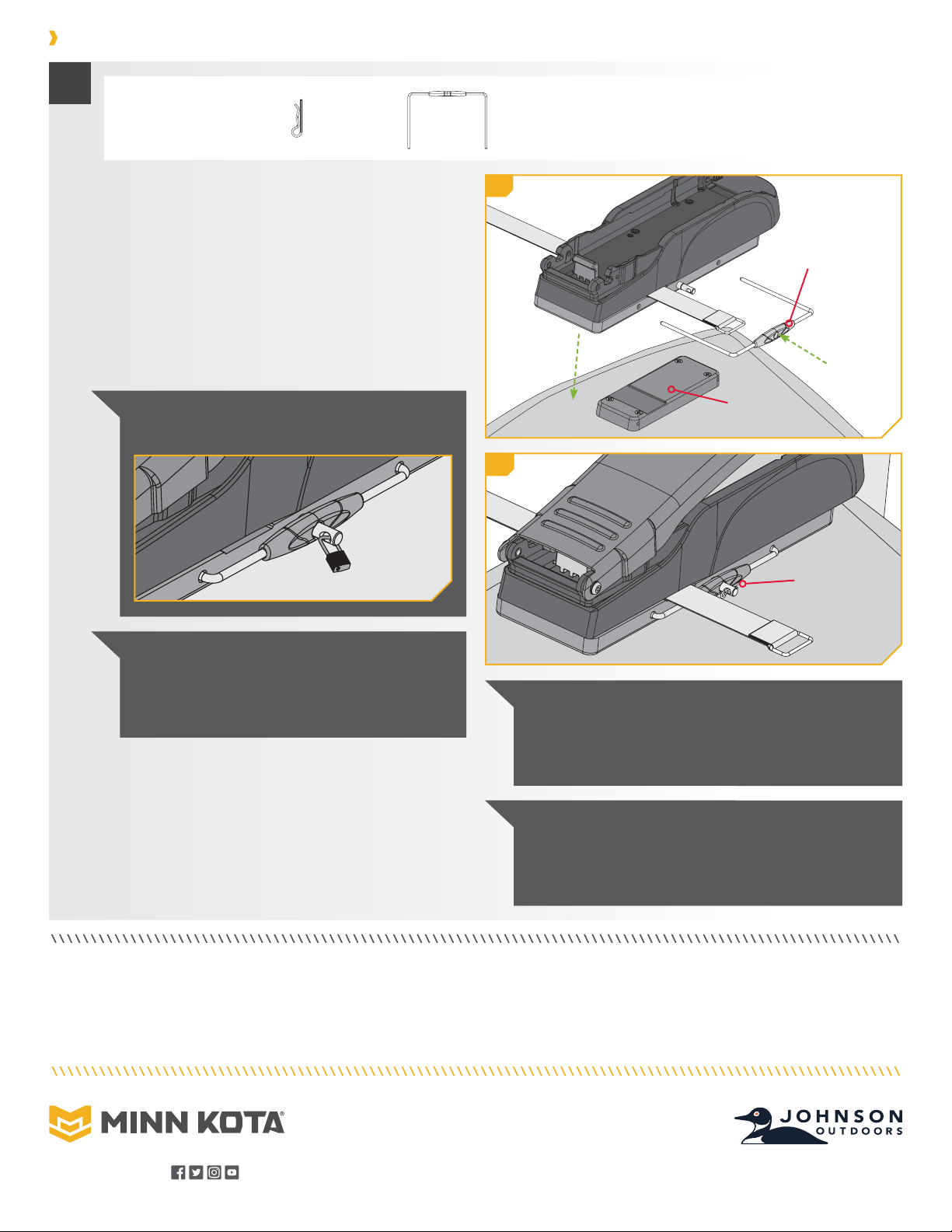
e. Le placement de la boucle sur la sangle de
stabilisation est basé sur la préférence personnelle et
celle-ci peut être placée soit en-bord ou hors-bord.
Le crochet et la boucle sur la fixation devraient être
tournés vers le bas pour que la sangle de stabilisation
fonctionne. Faites un test de l’emplacement de la
sangle de stabilisation pour s’assurer qu’elle peut
retenir le support tel qu’installé.
f. Alignez l’extrusion de la base avec les trous de montage
de la plaque externe.
RainureRainure
Plaque externePlaque externe
Sangle de stabilisationSangle de stabilisation
3
Hors-bordHors-bord
En-bordEn-bord
BoucleBoucle
ATTENTION
La sangle de stabilisation doit être située dans la rainure afin
d’éviter une défaillance du support à dégagement rapide.
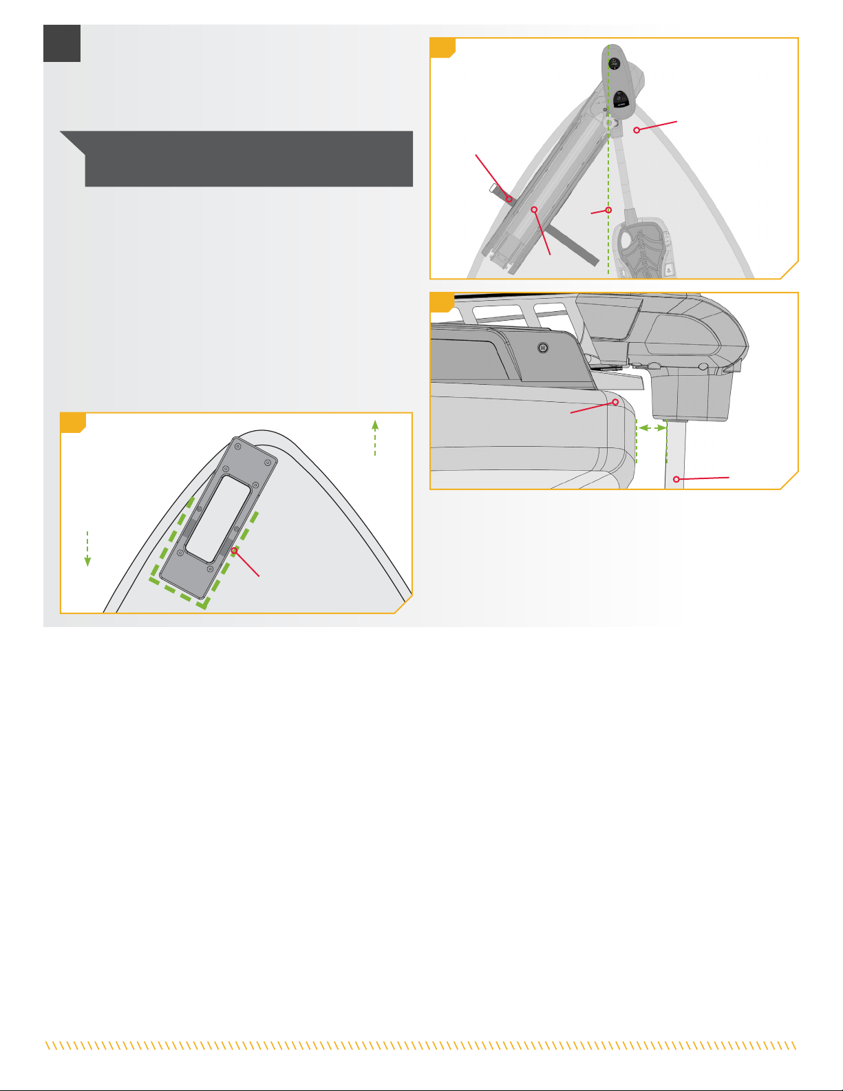
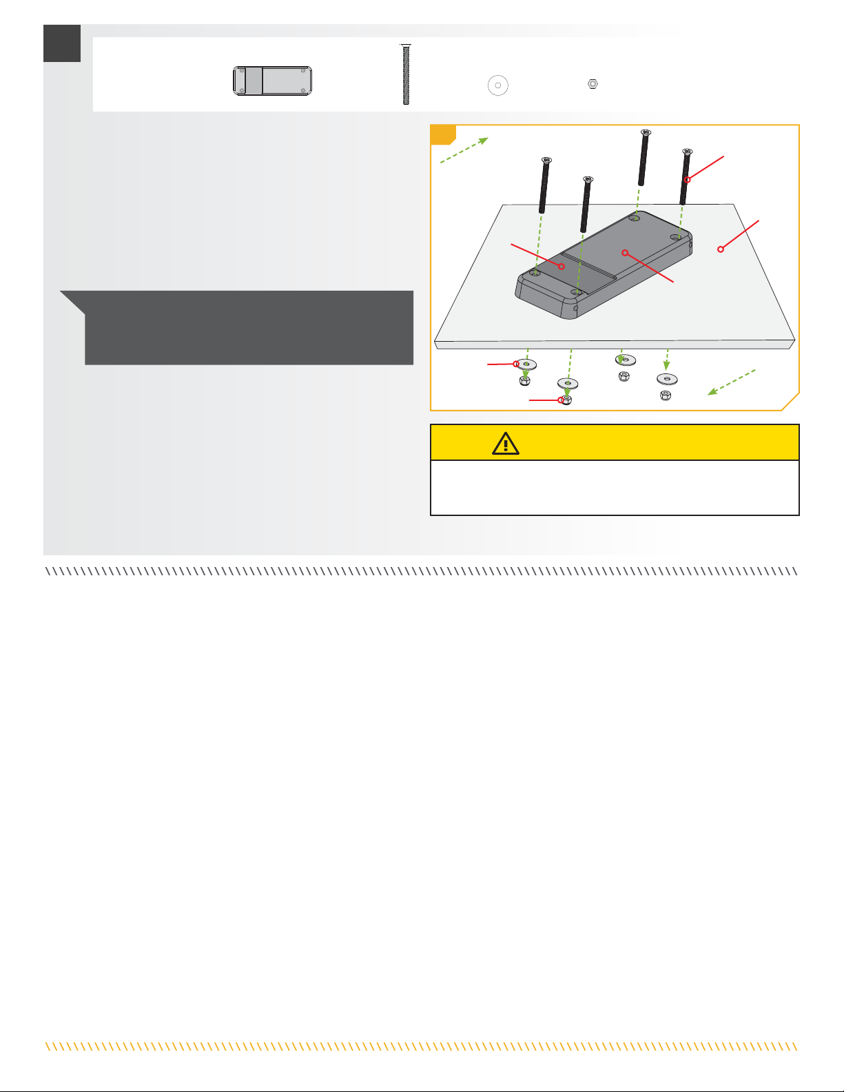
#4 x 1
ARTICLE(S) REQUIS
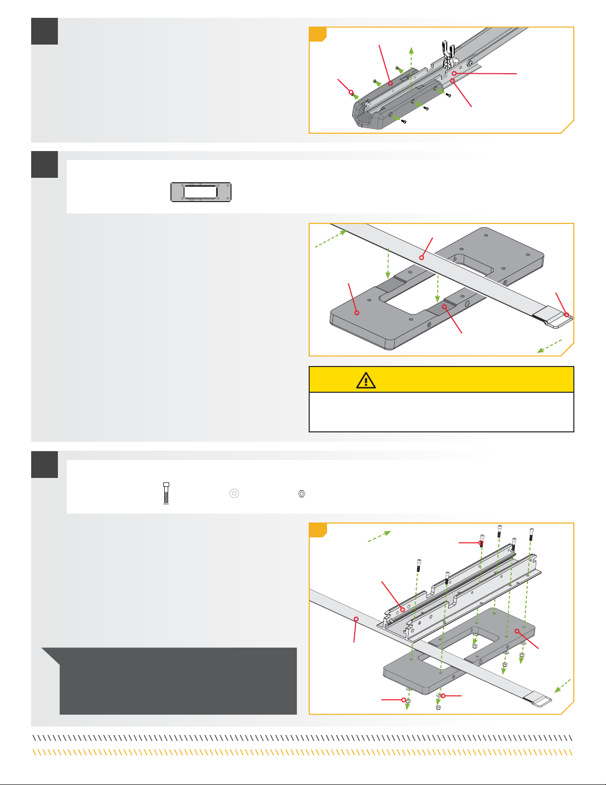
g. À l’aide d’une clé à douille, fixez l’extrusion de la base à
la plaque externe avec six vis à tête cylindrique à six pans
creux de 1/4 po x 1 1/8 po (6,4 mm x 28,6 mm) (article
nº 22), six rondelles plates (article nº 18) et six écrous
Nylock (article nº 24). Les vis devraient passer à travers
l’extrusion de la base, puis la plaque externe, ensuite les
rondelles plates, et être fixées avec des écrous Nylock.
h. Réinstallez le support du moteur qui a été retiré en
utilisant les vis et un tournevis nº 2.
4
#22 x 6 #18 x 6 #24 x 6
ARTICLE(S) REQUIS
AVIS : Pour prévenir le grippage de la quincaillerie en
acier inoxydable, n’utilisez pas d’outils haute vitesse pour
l’installation. Le fait de mouiller les vis ou d’appliquer un
produit antigrippant peut aider à prévenir qu’elles grippent.
4g
ExtrusionExtrusion
de la basede la base
VisVis
PlaquePlaque
externeexterne
RondelleRondelle
plateplate
Écrou NylockÉcrou Nylock
Hors-bordHors-bord
En-bordEn-bord
Sangle deSangle de
stabilisationstabilisation
13 | minnkotamotors.com ©2020 Johnson Outdoors Marine Electronics, Inc.