Elka ES 50 User manual

Installation and operating instructions
Barriers
ES 50 – ES 80
with MO 63
Translation of original operating manual
D-ID: V7_0 – 07.17

ES 50 – ES 80
1
Contents
1Preface ............................................................................................................................ 3
1.1General notes ................................................................................................................... 3
1.1.1Symbol explanation .......................................................................................................... 4
1.2Copyright .......................................................................................................................... 4
1.3Information regarding installation instruction .................................................................... 4
2Safety ............................................................................................................................... 5
2.1General notes on safety ................................................................................................... 5
2.2Notes on safety for the operation ...................................................................................... 5
2.3Safety notes for the operation with radio remote control .................................................. 5
2.4Intended use of barriers .................................................................................................... 5
2.5Improper use .................................................................................................................... 5
2.6Intended use – vehicle traffic, pedestrian traffic impossible .............................................. 6
2.7Intended use - vehicle traffic, pedestrian traffic not impossible ........................................ 6
2.8Danger, which could emanate from the site of operation .................................................. 7
2.9Non-factory technical alterations and extensions ............................................................. 7
2.10Personnel requirements – professional skills, knowledge and qualifications .................... 7
2.11Personal protective equipment ......................................................................................... 8
3Transportation and storing ............................................................................................ 9
3.1Transportation inspection ................................................................................................. 9
3.2Storing .............................................................................................................................. 9
3.3Lifting heavy loads ............................................................................................................ 9
4Declaration of conformity ............................................................................................ 10
4.1Barrier ES 50-80 – pedestrian traffic impossible ............................................................. 10
4.2Barrier ES 50-80 – pedestrian traffic not impossible ....................................................... 11
4.3Declaration of conformity – complete system ................................................................. 12
4.4Name plate ..................................................................................................................... 12
4.5Performance declaration ................................................................................................ 12
5Function description .................................................................................................... 13
6Technical data ES 50 – ES 80 ...................................................................................... 14
6.1Operation - Safety – Wind load class ............................................................................. 15
7Measurements ES 50 – ES 80 ...................................................................................... 17
8Installation ES 50 – ES 80 ............................................................................................ 18
9Controller MO 63 ........................................................................................................... 23
9.1Connections .................................................................................................................... 24
9.2Further connections ........................................................................................................ 24
9.3Visual indication .............................................................................................................. 25
9.4Operating mode controller .............................................................................................. 25
9.4.1Pre-warning before opening (VWA) ................................................................................ 25
9.4.2Pre-warning before closing (VWZ) .................................................................................. 25
9.4.3Automatic closure (ZLA) ................................................................................................. 26
9.4.4Reversal on hitting obstacles (REV) ............................................................................... 26
9.4.5Counting (ZÄHL) ............................................................................................................. 26
9.4.6Reversal during opening (SZ) ......................................................................................... 26
9.4.7Automatic closure by photo-cell (LSA) ............................................................................ 26
9.4.8Photo-cell test (LSTST) .................................................................................................. 26
9.5Photo-cell test ................................................................................................................. 26
9.6Programming .................................................................................................................. 27
9.6.1Running time and automatic closure .............................................................................. 27

ES 50 – ES 80
2
9.6.2Personal code for radio remote ...................................................................................... 27
10External connections ................................................................................................... 29
11Layout in the barrier ..................................................................................................... 31
12Fault finding .................................................................................................................. 32
12.1The closed barrier doesn’t react to a signal to open ....................................................... 32
12.2The open barrier doesn’t react to signals to close .......................................................... 33
12.3Fault finding continued ................................................................................................... 34
12.4Error code ....................................................................................................................... 35
13Examples for use of loop detectors ............................................................................ 36
14Maintenance and cleaning ........................................................................................... 38
14.1Maintenance ................................................................................................................... 38
14.2Cleaning ......................................................................................................................... 38
14.2.1Cleaning – outer sides of the barrier housing ................................................................. 38
14.2.2Cleaning- inside of the housing ...................................................................................... 39
15Decommissioning ......................................................................................................... 40
15.1Disposal .......................................................................................................................... 40
16Extra equipment ........................................................................................................... 41
16.1Swinging support for ES 50 – 80 .................................................................................... 41
16.2Fixed support with electromagnet ................................................................................... 42
17Layout (exploded drawing) .......................................................................................... 43
17.1Layout ES 50 - 80 ........................................................................................................... 43

ES 50 – ES 80
3
1 Preface
1.1 General notes
These operating instructions must be available on site at all times. It should be read thoroughly by all
persons who use, or service the appliances. Improper usage or servicing or ignoring the operating
instructions can be a source of danger for persons, or result in material damage. If the meaning of any
part of these instructions isn’t clear, then please contact ELKA-Torantriebe GmbH u. Co. Betriebs KG
before you use the appliance.
This applies to all setup procedures, fault finding, disposal of material, care and servicing of the
appliance. The accident prevention regulations and applicable technical regulations (e.g. safety or
electrical) and environment protection regulations of the country in which the appliance is used also
apply.
All repairs on the appliances must be carried out by qualified persons. ELKA-Torantriebe GmbH u. Co.
Betriebs KG accepts no liability for damage which is caused by using the appliance for purposes other
than those for which it is built.
ELKA-Torantriebe GmbH u. Co. Betriebs KG cannot recognise every possible source of danger in
advance. If the appliance is used other than in the recommended manner, the user must ascertain that
no danger for himself or others will result from this use. He must also ascertain that the planned use
will have no detrimental effect on the appliance itself. The appliance should only be used when all
safety equipment is available and in working order. All faults which could be a source of danger to the
user or to third persons must be eliminated immediately. All warning and safety notices on the
appliances must be kept legible.
All electrical periphery equipment which is connected to the appliance must have a CE Mark, which
ensures that it conforms to the relevant EEC regulations. Neither mechanical nor electrical alterations
to the appliance, without explicit agreement of the manufacturer, are allowed. All alterations or
extensions to the appliance must be carried out with parts which ELKA-Torantriebe GmbH u. Co.
Betriebs KG have defined as suitable for such alterations, and be carried out by qualified personnel.
Please note that with any alteration of the product, no matter whether mechanical or electrical, the
warranty expires and the conformity is revoked. Only the use of ELKA accessories and original ELKA
spare parts is allowed. In case of any contravention ELKA disclaims liability of any kind.
INFORMATION!
The operation of the system within CEN countries must also be conformant with the European safety-
relevant directives and standards.
We reserve the right to make technical improvements without prior notice.

ES 50 – ES 80
4
1.1.1 Symbol explanation
WARNING!
Remarks regarding the safety of persons and the gate opener itself are marked by special
symbols. These remarks have to be absolutely observed in order to avoid accidents and
material damage.
DANGER!
…points to an imminent dangerous situation, which can cause death or serious injuries if it is
not avoided.
WARNING!
…points to a potentially dangerous situation, which can cause death or serious injuries if it is
not avoided.
ATTENTION!
…points to a potentially dangerous situation, which can cause minor or slight injuries if it is not
avoided.
ATTENTION!
…points to a potentially dangerous situation, which can cause property damage if it is not
avoided.
REMARK!
Important notice for installation or functioning.
1.2 Copyright
The operating manual and the contained text, drawings, pictures, and other depictions are protected by
copyright. Reproduction of any kind – even in extracts – as well as the utilization and/or communication
of the content without written release certificate are prohibited. Violators will be held liable for damages.
We reserve the right to make further claims.
1.3 Information regarding installation instruction
This document is to be used as installation instruction for partly completed machinery (according to
machinery directive 2006/42/EG, article 13, (2)).

ES 50 – ES 80
5
2 Safety
2.1 General notes on safety
The valid regulations and standards have to be observed during installation and operation, e.g. DIN EN
13241, DIN EN 12445, DIN EN 12453 etc.
Only the use of spare parts made by the original manufacturer is allowed. Do not put a defective gate
opener / barrier into operation.
After set-up (installation) every user of the equipment has to be instructed about the operation and
function of the gate opener / barrier.
In order to reduce the risk potential related to the movement of the barrier boom, additional optical
and/or acoustical warning devices should be installed.
2.2 Notes on safety for the operation
Children from the age of 8 years and persons with reduced physical sensory or mental capabilities or
lack of experience and/or knowledge may use these devices, provided they are supervised or have
been instructed in the safe use of the device, and have understood the hazards involved. Children
must not play with the device.
No persons, objects, or animals are allowed within the range of the gate movement / barrier movement
during opening or closing.
Never reach into moving parts of the gate operator, gate or barrier.
Drive through the gate system /barrier only after complete opening.
The gate system / barrier has to be secured depending on the type of usage, corresponding to the valid
standards and regulations (e.g. safety at the main and secondary closing edges).
The safety devices have to be checked regularly for functioning according to the standards and
regulations, at least once a year.
2.3 Safety notes for the operation with radio remote control
The radio remote control should only be used, if the area of movement of the gate / barrier is always
completely visible by the operator and thus it is assured, that no person, object, or animal is present
within this range of movement.
The radio remote control transmitters have to be carefully kept, so that an unintentional use is
impossible.
Radio remote controls should not be operated at radio-technical sensitive locations, like airports or
hospitals.
Interferences by other (properly operated) radio communication installations, which are used within the
same frequency range, cannot be ruled out.
2.4 Intended use of barriers
The vehicle barriers model ES 50-80 are exclusively intended for controlling access to and exit of
certain road vehicles in or from certain areas.
The barrier is either controlled by a person in manual operating modes or by access control systems in
automatic operating modes and monitored by induction loops and/or safety facilities.
WARNING!
Danger through improper use!
Each improper use can lead to dangerous situations.
Any use above and beyond the expressly described intended use is prohibited.
Definition - vehicles, when using the barrier models ES 50-80
Vehicles are all vehicles which are used for the carriage of persons or goods and which participate in
road traffic.
Road vehicles need to have sufficiently large metal areas in the vehicle floor area to enable
detection by induction loops. The induction loop function is significantly dependent on this
metalarea.
For all other road vehicles other or complementary safety facilities must be installed.
In general additional safety facilities must be installed for motorcycles and bicycles.
2.5 Improper use
The regulation of pedestrian traffic with the vehicle barriers ES 50-80 is contrary to the intended use.
ES 50 – ES 80
6
The barriers model ES 50-80 are no railway crossing gates and must not be used at railway crossings.
The barriers are not approved for bicycles or animals.
The barriers must not be used in explosive environments.
WARNING!
Danger through non-intended use!
Every non-intended use can lead to dangerous situations.
Any use above and beyond the above mentioned use is prohibited and constitutes improper use.
2.6 Intended use – vehicle traffic, pedestrian traffic impossible
The operational safety can only be ensured when the barrier is used as intended.
After installation, the barriers of the series ES 50-80 serve as passage control of vehicle paths.
Notes for danger area, when pedestrian traffic is impossible:
WARNING!
Danger of impact and crushing in the danger area!
Keep people away from the danger area in which the barrier with pedestrian traffic impossible use
is being used!
WARNING!
Danger of impact and crushing in the danger area!
Entering the danger area can cause death or serious injuries!
Mark the danger area by prohibition signs.
Set up barriers such as fences and railings.
Set up separate passageway for persons and bicycles outside the danger area.
Observe county-specific regulations (regulations and laws).
CAUTION!
Risk of injury by entering the danger zone!
With inadequate safety measures the movement of the barrier boom can cause injuries.
In order to reduce the risk potential related to the movement of the barrier boom, additional at least
one additional optical presence detection or safety features (e.g. photoelectric barriers) must be
installed if the barrier is installed in public areas.
The controller is a product component and serves to control the barrier.
Any use above and beyond the above mentioned use is prohibited and constitutes improper
use.
2.7 Intended use - vehicle traffic, pedestrian traffic not impossible
The operational safety can only be ensured when the barrier is used as intended.
After installation, the barriers of the series ES 50 – ES 80 serve as passage control of vehicle paths.
Any use above and beyond the above mentioned use is prohibited and constitutes improper
use.
Through the installation of suitable safety devices ELKA-barriers of the types ES 50 - 80 can
also be used where passenger traffic cannot be excluded.
Notes to the danger area pedestrian traffic not impossible:
WARNING!
Danger of impact and crushing in the danger area!
People could be present in the danger area of barriers where personal traffic cannot be excluded!
CAUTION!
Danger of impact and crushing in the danger area!
Entering the danger area can cause serious personal injuries.
Mark the danger area by prohibition signs.
Observe county-specific regulations (regulations and laws).
CAUTION!
Danger of impact and crushing in the danger area!
Safety measures for vehicles and trucks cannot protect bicycles, motorcycles and other vehicles.
For bicycles, motorcycles and other road vehicles other or complementary safety facilities must be
installed.

ES 50 – ES 80
7
Notes for the barrier boom specification:
WARNING!
Danger of impact and crushing!
Through additional installations on the barrier boom, e. g. swinging support, force at the main closing
edge outside the permitted range can arise.
Additional installations on the barrier boom are not allowed.
For the different barrier models the only use of the original specified ELKA barrier booms is
allowed.
Notes on safety:
CAUTION!
Risk of impact or crushing!
With inadequate safety measures the movement of the barrier boom can result in impact or crushing
points between the boom and solid objects within the movement area.
Suitable safety devices for the protection of persons must be installed.
In order to reduce the potential danger during the barrier boom movement, additional optical
and/or acoustic warning devices should be installed.
2.8 Danger, which could emanate from the site of operation
The barriers ES 50 – ES 80 operate with moving parts.
WARNING!
Rotating and/or linear movable components can cause serious injuries.
Do not reach into moving parts or handle any moving components during operation.
Turn the appliance off before any maintenance work, repair work or other work and secure it
against unintentional restarting.
2.9 Non-factory technical alterations and extensions
Non-factory technical alterations and/or extensions may result in hazards as well as interfere with the
function of the barrier.
DANGER!
Danger through voltage!
Risk of death by electric shock!
Technical alterations may only be performed by skilled personnel and only according to the
manufacturer’s instructions.
CAUTION!
Danger of injury through defective components!
Mechanical and electrical alterations can influence the functioning of the barrier!
Technical alterations may only be performed by skilled personnel and only according to the
manufacturer’s instructions.
CAUTION!
Malfunctioning of the barrier!
Mechanical and electrical alterations can influence the functioning of the barrier!
Technical alterations may only be performed by skilled personnel and only according to the
manufacturer’s instructions.
2.10 Personnel requirements – professional skills, knowledge and qualifications
WARNING!
Risk of injury through inadequate qualification!
Improper handling during installation, maintenance, repair work or dismantling can result in personal
injury and/or property damage.
Work during installation, maintenance, repair and dismantling must be performed by skilled
personnel only.
Specialist - is a person with suitable professional training, knowledge and experience, who can
recognize and avoid danger.
Instructed person - is a person, which was instructed in the operation and use.

ES 50 – ES 80
8
2.11 Personal protective equipment
During installation, maintenance, repair work and dismantling of the barrier suitable personal protective
equipment must be worn.
CAUTION!
Bruising/jamming/driving over (e.g. by material handling equipment, industrial trucks) the feet,
contusion by falling heavy objects, cutting injuries by stepping into pointed/sharp objects.
Foot injuries
Wearing of suitable safety shoes during the installation, maintenance, repair work and dismantling
protects against serious foot injuries with long-lasting consequences.
CAUTION!
Falling heavy objects hitting the head
Head injuries
Wearing of a suitable safety helmet during the installation, maintenance, repair work and
dismantling protects against serious head injuries with long-lasting consequences.
CAUTION!
Cutting injuries resulting from pointed/sharp objects
Hand injuries
Wearing of suitable safety gloves during the installation, maintenance, repair work and dismantling
protects against serious hand injuries with long-lasting consequences.
CAUTION!
Injuries resulting from drilling chips or saw dust
Eye injuries
Wearing of suitable safety goggles during the installation and repair work protects against serious
eye injuries with long-lasting consequences.

ES 50 – ES 80
9
3 Transportation and storing
3.1 Transportation inspection
The shipment has to be inspected for transportation damage immediately after receipt. In case of any
damage record the type and extent on the delivery receipt or refuse acceptance.
Inform ELKA-Torantriebe immediately in the event of damage.
In case the above points are not observed claims will be denied due to insurance regulations.
3.2 Storing
The barrier has to be stored as follows:
Do not expose the barrier to aggressive substances.
Do not expose the barrier to heat sources.
Storage temperature -20°C to +70°C.
3.3 Lifting heavy loads
WARNING!
Risk of injury by lifting heavy loads!
Lifting heavy loads may cause serious injuries.
Never lift the barrier single-handedly.
To lift the barrier, use a suitable lifting device.
Wear suitable safety shoes.
ES 50 – ES 80
10
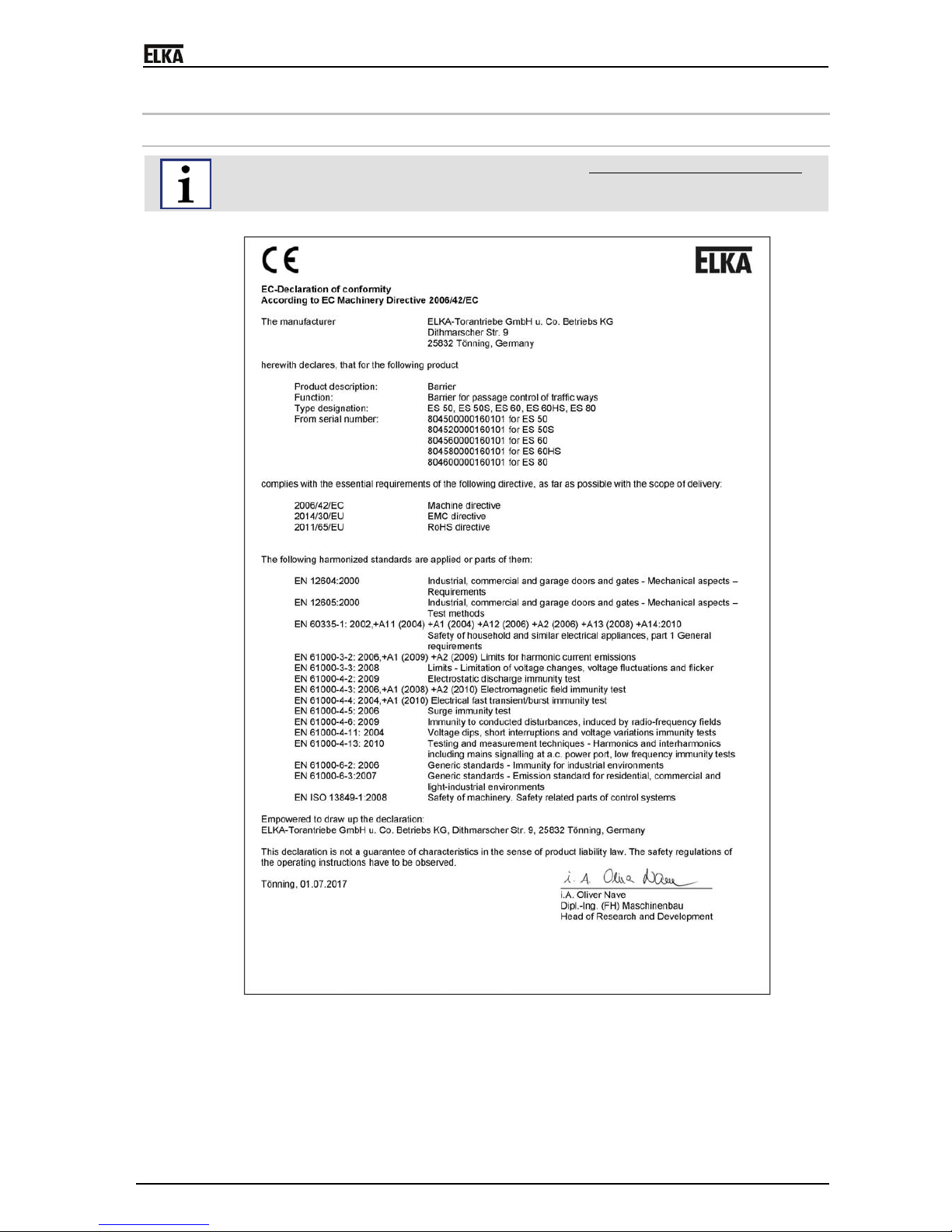
4 Declaration of conformity
4.1 Barrier ES 50-80 – pedestrian traffic impossible
The declaration of conformity below is valid for barriers where pedestrian traffic can be excluded.
Drawing 1

ES 50 – ES 80
11
4.2 Barrier ES 50-80 – pedestrian traffic not impossible
The declaration of conformity below is valid for barriers where pedestrian traffic cannot be excluded.
Drawing 2
Suitable safety devices for the protection of persons must be installed. Only with the (on site)
installation of suitable safety devices for the protection of persons the barrier is confirm with EN 13241.

ES 50 – ES 80
12
4.3 Declaration of conformity – complete system
After the installation an EG-declaration of conformity according to EC-machinery directive 2006/42/EG
for the complete system has to be issued by the person responsible for the integration (according to
product standard DIN EN 13241).
4.4 Name plate
The name plate of the barrier is attached at the inside front of the barrier housing.
4.5 Performance declaration
The performance declaration (pursuant to EC Machinery Directive No. 305/2011) is attached to the
product as a special annex.

ES 50 – ES 80
13
5 Function description
Barriers serve as passage control of vehicle paths. By raising and lowering of the barrier boom the
passage is granted or obstructed.
For a boom length of 4,000mm and longer we recommend the use of a fixed or swinging support, for a
boom length of 5,000mm and longer the use of a fixed or swinging support is mandatory.
The controller offers the possibility to activate the barrier by radio remote control.
The controller is able to observe the max. permitted force which was set before in the learning
sequence. If during the closing movement more force is needed, the barrier reverses. Additionally
several different safety features, e.g. photoelectric barriers, can be connected.
Safety devices (photoelectric barriers, light curtains etc.) must be installed on site. The safety devices
and induction loops must ensure that the barrier danger area is clear before the barrier closes.
ES 50 – ES 80
14
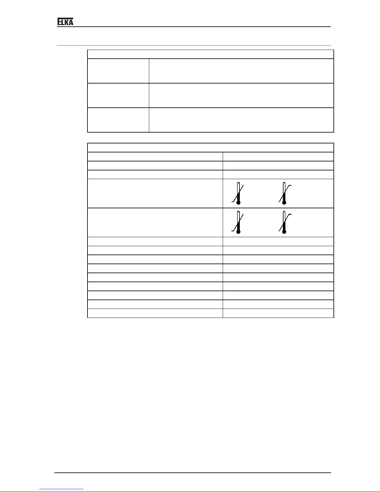
6 Technical data ES 50 – ES 80
Operative range
Application for… Parking area, parking garage
Company entrance
Safety area
Drive pulse from… Push-button, card reader, key switch, desk top panel etc.
remote control
Induction loop
Safety Reversing on obstacle
Best protection against vandalism
Ergonomic emergency release
Table 1
General data
Mains supply 230V / 50Hz
Max. current 10A (max.)
Duty cycle 100%
Ambient temperature range
-20°C to +70°C
Storage temperature range
-20°C to +70°C
Relative humidity max. 95%, non-condensing
Controller MO 63
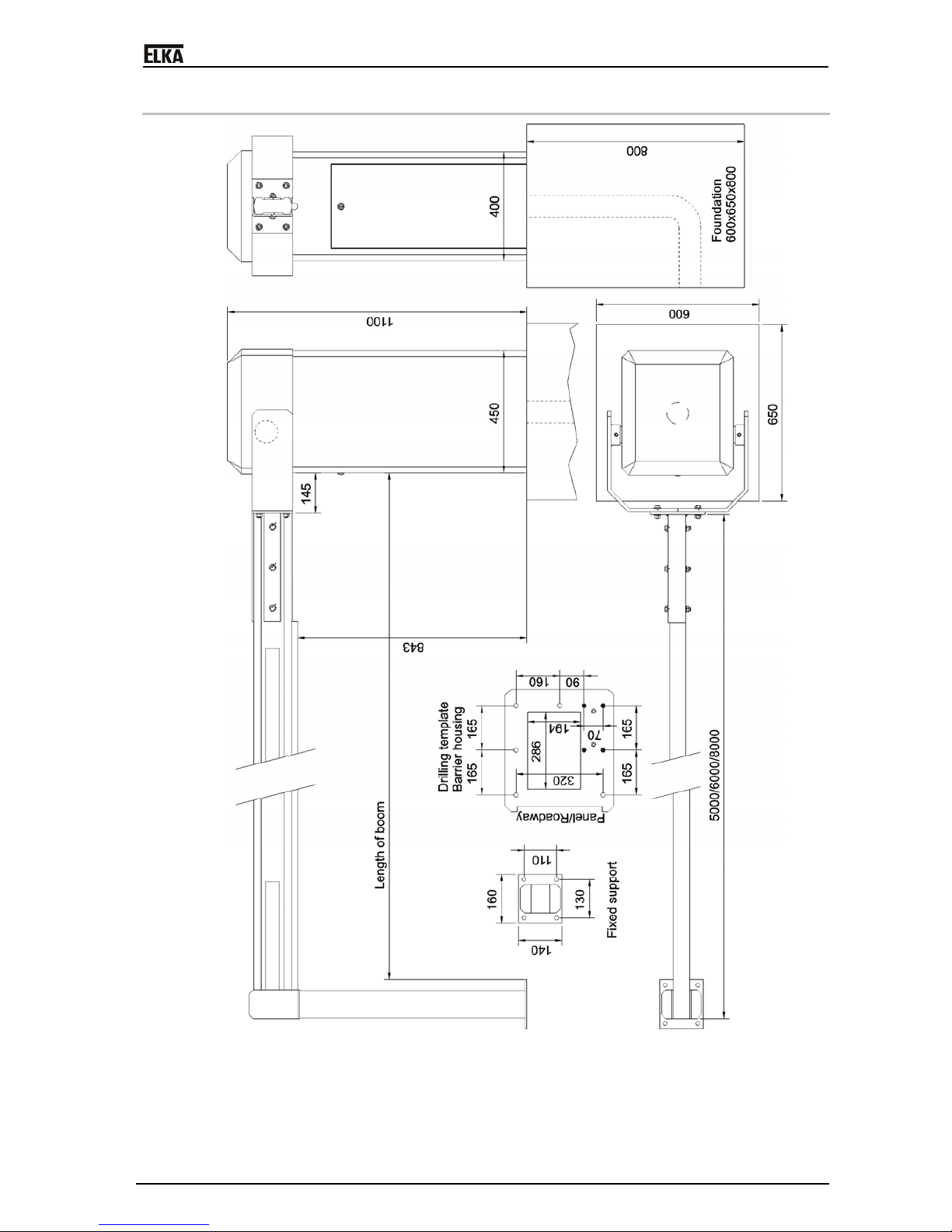
Measurements (w/l/h) 400x450x1.100mm
Foundation (frost-proofed) 600x650x800mm
Boom connector central
Housing aluminium
Mechanical parts steel, zinc coated
Sound pressure level (distance 1m) ≤ 60 dB(A)
Degree of protection IP 44
Table 2

ES 50 – ES 80
15
Typical Data ES 50 ES 50S ES 60 ES 60HS ES 80
Drawn power [kW] 0.26 0.37 0.26 0.37 0.26
Opening and closing time
[s]
approx. 4.0 approx. 4.0 approx. 5.5 approx. 4.0 approx. 8.5
Max. boom length [mm] 5,000 5,000 6,000 6,000 8,000
Effective length [mm] 5,140 5,140 6,140 6,140 8,140
Fixed support / swinging
support
required required required required required
Reversing on obstacle selectable selectable selectable selectable selectable
Boom weight [kg] 10 10 16.5 16.5 23
Boom weight (round boom,
optional) [kg]
9 9 11 11 18.5
Barrier weight [kg] approx. 116 approx. 116 approx. 124 approx. 124 approx. 138
Table 3
The barriers ES 50 to ES 80 are for vehicle-traffic only!
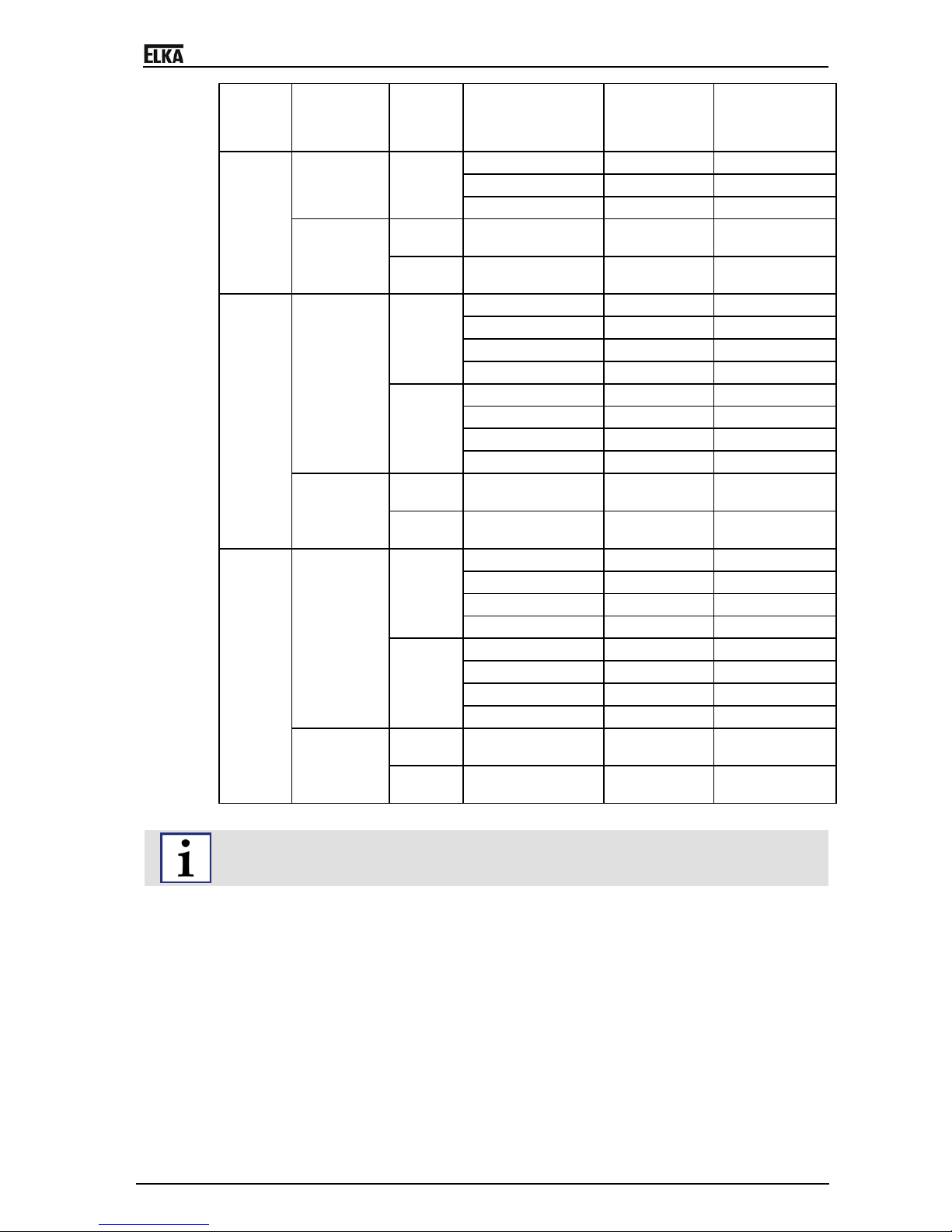
6.1 Operation - Safety – Wind load class
WARNING!
Risk through high wind loads!
The barrier use during high wind loads can lead to barrier boom damage and/or damage to the boom
connector.
The barrier use during higher wind loads as shown in the table below is prohibited.
The figures below refers to the closed barrier and not to the ability to open and close the barrier
during high wind loads.
During high wind loads the barrier boom must be secured or dismantled!
Type Barrier
boom
Swinging
support /
Fixed
support
Folding skirt
or
top and bottom
skirt
max. permitted
wind load
class
Windspeed
(km/h)
ES 50 Standard
boom
Swinging
support
without 4 up to max. 133
HG 75 2 up to max. 90
Fixed
support
without 4 up to max. 133
HG 75 3 up to max. 117
Round
boom
Swinging
support
without 4 up to max. 133
Fixed
support
without 4 up to max. 133
ES 50 S Standard
boom
Swinging
support
without 4 up to max. 133
HG 75 2 up to max. 90
Fixed
support
without 4 up to max. 133
HG 75 3 up to max. 117
Round
boom
Swinging
support
without 4 up to max. 133
Fixed
support
without 4 up to max. 133
ES 60 Standard
boom
Swinging
support
without 4 up to max. 133
HG 75 3 up to max. 117
HG 150 (max. 4.5m) 4 up to max. 133
SG 150 (max. 4.5m) 4 up to max. 133
Fixed without 4 up to max. 133
ES 50 – ES 80
16
Type Barrier
boom
Swinging
support /
Fixed
support
Folding skirt
or
top and bottom
skirt
max. permitted
wind load
class
Windspeed
(km/h)
support HG 75 4 up to max. 133
HG 150 (max. 4.5m) 4 up to max. 133
SG 150 (max. 4.5m) 4 up to max. 133
Round
boom
Swinging
support
without 4 up to max. 133
Fixed
support
without 4 up to max. 133
ES 60HS Standard
boom
Swinging
support
without 4 up to max. 133
HG 75 3 up to max. 117
HG 150 (max. 4.5m) 4 up to max. 133
SG 150 (max. 4.5m) 4 up to max. 133
Fixed
support
without 4 up to max. 133
HG 75 4 up to max. 133
HG 150 (max. 4.5m) 4 up to max. 133
SG 150 (max. 4.5m) 4 up to max. 133
Round
boom
Swinging
support
without 4 up to max. 133
Fixed
support
without 4 up to max. 133
ES 80 Standard
boom
Swinging
support
without 3 up to max. 117
HG 75 2 up to max. 90
HG 150 (max. 6m) 2 up to max. 90
SG 150 (max. 6m) 2 up to max. 90
Fixed
support
without 4 up to max. 133
HG 75 4 up to max. 133
HG 150 (max. 6m) 4 up to max. 133
SG 150 (max. 6m) 4 up to max. 133
Round
boom
Swinging
support
without 4 up to max. 133
Fixed
support
without 4 up to max. 133
Table 4
The wind speeds are statistic maximum values.
ES 50 – ES 80
17
7 Measurements ES 50 – ES 80
Drawing 3

ES 50 – ES 80
18
8 Installation ES 50 – ES 80
Basic requirements
Keep a safety distance of min. 500mm between all moving barrier parts and surrounding objects
like walls, fences etc.
When preparing the foundation consider the alignment and distance related to a (optional) fixed
support.
The installation of barriers in flood areas is prohibited.
REMARK!
For the barrier foundation we recommend a concrete strength class of C20/25 (or higher) and the use
of chemical dowels (M12).
WARNING!
Risk of injury by insufficient fastening!
Tilting barrier housings can result in severe injuries.
Before installation ensure a safe stand oft he barrier housing.
Do not lean the barrier boom against a wall or similar before isntallation. Store the boom
horizontally only.
Install the barrier housing as specified.
Use the recommended heavy duty anchor bolts M12, at least M10 is required.
During maintenance check the housing for a correct fasenting on the foundation.
1. Before preparing the foundation lay enough underground cable (provide for a sufficient number of
wires) or a plastic cable conduit for a later cable installation. The foundation has to be absolutely
frost-free and with a horizontal surface of 600 x 650mm (if possible, at least 30mm higher than the
surrounding ground).
Drawing 4
2. Using the provided template you can either grout bolts (min. 12mm) into the foundation at the
appropriate positions or drill holes into the hardened concrete for heavy-duty fixings. Secure the
barrier on its foundation. For a correct functioning make sure the barrier housing is in a
perpendicular position.
A
nchor the spring assembly with all four fastening points through the housing into the foundation (see
drilling template ).
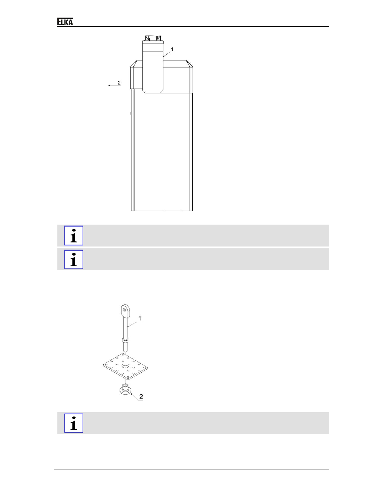
3. To open (release) the barrier boom during installation and current failure, pull the release lever
(2). The barrier can now be opened manually. In the vertical position the bolt (1) engages
automatically. To close (reposition) the barrier boom pull the lever again and move the boom
manually downwards.
ES 50 – ES 80
19
Drawing 5
The barrier is open when delivered, i.e. the boom connector wings have to be mounted vertically
upwards. During mounting the larger hub distance has to point in direction to the access panel (2).
Please also observe the stickers at the boom connector wings („OBEN-TOP-HAUT”).
The wings (1) for the boom connectors are different for the left and right side.
The wings are numbered (on the carton) in pairs and each pair is assigned for a certain barrier
mechanics.
4. Connect the wings for the boom connector to both ends of the main shaft. 4 of the 16 tapped holes
are numbered in handwriting and the inserted grub screws have to be tightened in the
corresponding order.
5. Secure the boom holder on the assembly. The two parts are then joined together.
Drawing 6
For the above drawing the tension springs were graphically removed. Do not loosen the tension
springs from the spring plate during installation / disassembly of the spring assembly.
6. Remove the adjusting nut from the spring assembly. If the boom is to be shortened reduce the
number of springs. The following table shows approximate values, check that the balance is as
described under f). The springs must be divided equally between the back and the front. One
This manual suits for next models
4
Table of contents
Other Elka Control System manuals


Popular Control System manuals by other brands


Extron electronics
Extron electronics TouchLink TLC Pro 526M Series user guide

Strand
Strand Vision.net RS232 user manual

DANHAG
DANHAG APP-control operating manual

Niles
Niles WVC100 Specifications

ENTRYPASS
ENTRYPASS EP.MINI Wiring guide

tbs electronics
tbs electronics H64 Installation instructions & user manual


