Song Meter SM4 User Guide
Wildlife Acoustics, Inc. page i
TABLE OF CONTENTS
1Quick Start Guide 3
2Overview 4
Song Meter with Analysis and Remote Transfer ...........................................................................................4
SMART Linux Resources Guide .....................................................................................................................4
Technology ...................................................................................................................................................4
Updates........................................................................................................................................................4
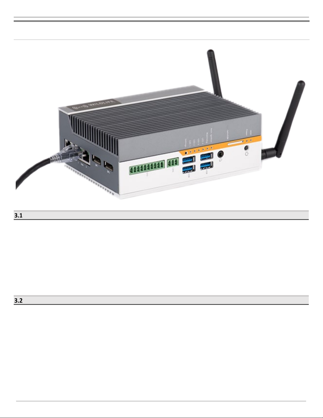
3SMART Controller 5
Overview......................................................................................................................................................5
Power Requirements....................................................................................................................................5
SMART Controller Processing Limitations.....................................................................................................6
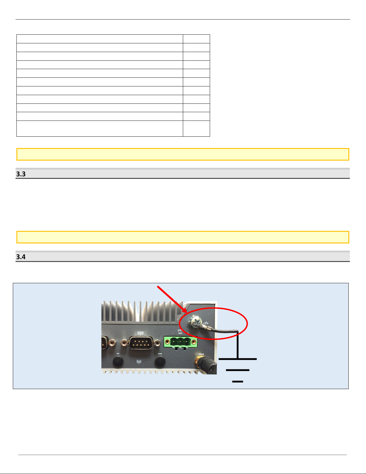
Grounding ....................................................................................................................................................6
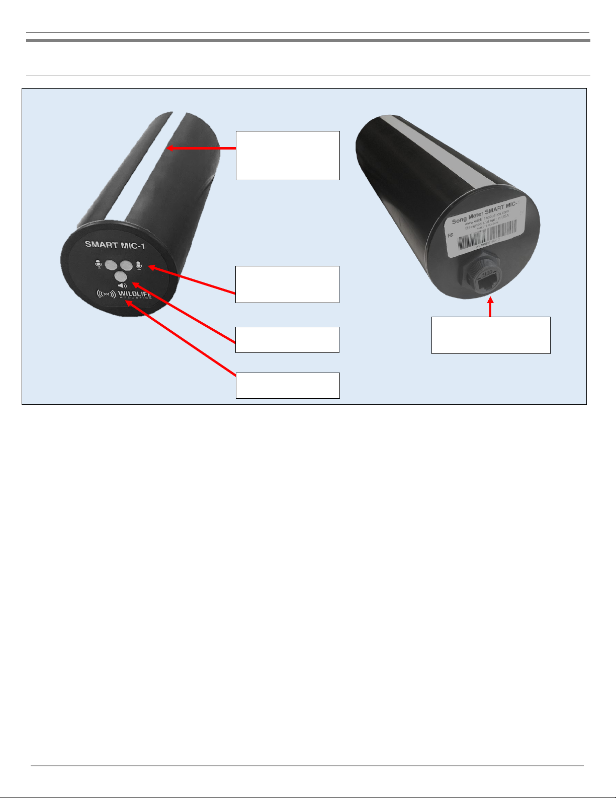
4SMART MIC-1 8
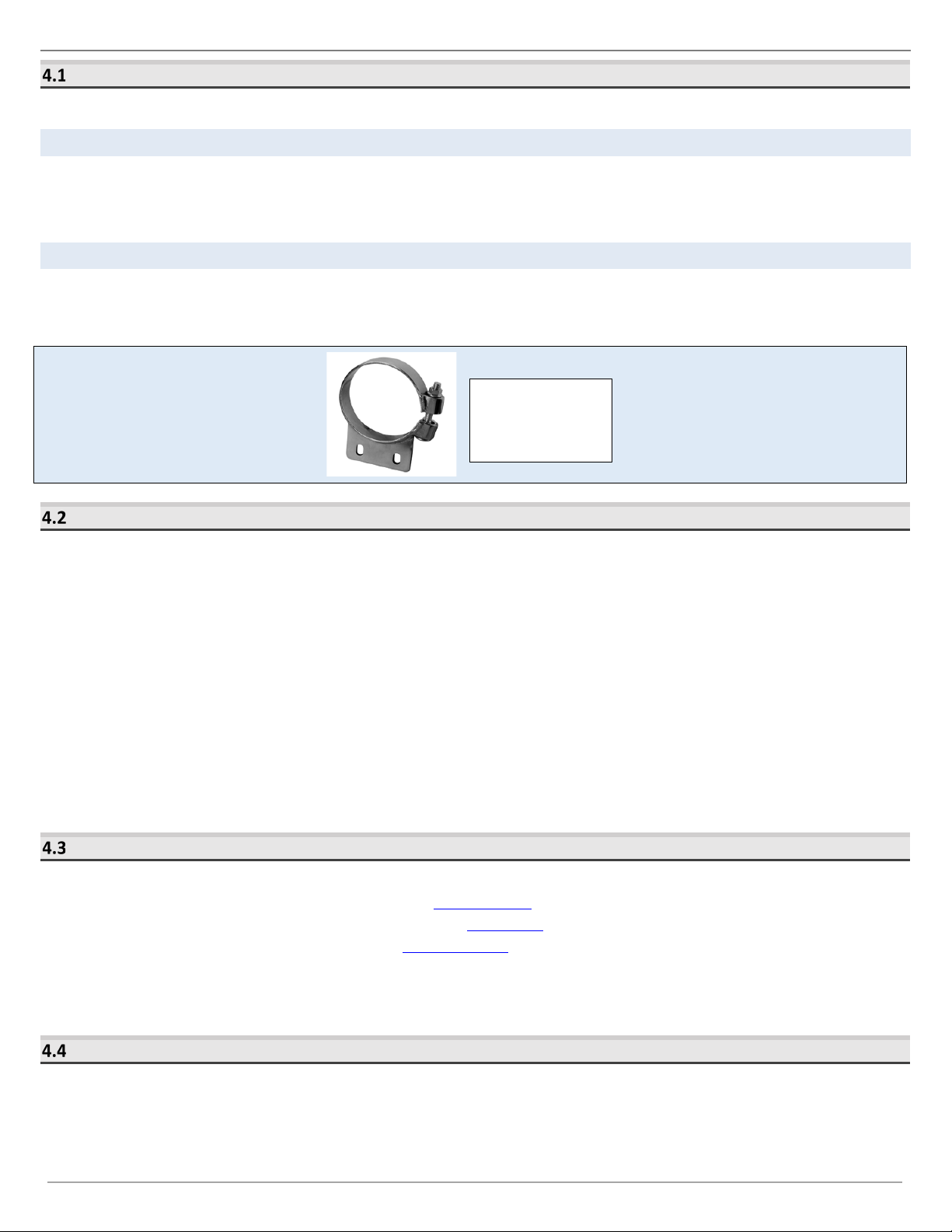
Enclosure and Mounting...............................................................................................................................9
Connection ...................................................................................................................................................9
Configuration ...............................................................................................................................................9
Ultrasonic Sensors........................................................................................................................................9
Ultrasonic Speaker .....................................................................................................................................10
Heater ........................................................................................................................................................10
RJ45 Weatherproofing and Ferrite Kit ........................................................................................................ 10
RJ45 Surge Protector ..................................................................................................................................14
Example SMART MIC-1 Configurations .......................................................................................................15
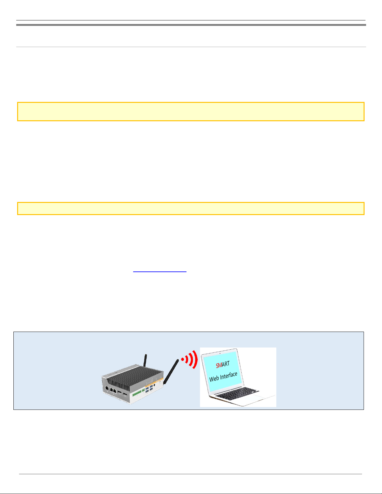
5SMART Web Interface 17
Connect To The SMART Web Interface ....................................................................................................... 17
Devices Tab ................................................................................................................................................18
Data Files Tab .............................................................................................................................................20
Settings Profiles Tab ...................................................................................................................................21
Schedule Profiles Tab ................................................................................................................................. 27
Time and Location Tab ...............................................................................................................................31
Serial Output Tab ....................................................................................................................................... 32
Networking Tab..........................................................................................................................................33
Maintenance Tab .......................................................................................................................................37
Administration Tab.....................................................................................................................................40
6Connection to the SMART System 42
Direct Keyboard and Monitor..................................................................................................................... 42
Network Configuration............................................................................................................................... 42
WIFI............................................................................................................................................................43
RJ45 Ethernet .............................................................................................................................................44
Serial ..........................................................................................................................................................44
7SMART Internet Gateway 45
Connect the SMART System to the Internet ............................................................................................... 45
Configure the SMART System for Internet Gateway connection................................................................. 46
Configure Gateway access through WildlifeAcoustics.com......................................................................... 47
8Network Security 49
SMART System ...........................................................................................................................................49
Wildlife Acoustics IOT Gateway..................................................................................................................49
9Specifications 49
SMART Controller Specifications ................................................................................................................ 49
SMART Controller Dimensions.................................................................................................................... 50