Elko iNELS Air AirSS-100L User manual

1 / 4
AirSS-100L
02-50/2019 Rev.: 0
+
-
c
1
3
4
4
2
5
6
7
a
f
b
c
d
a
a
f
b
e
Characteristics
EN
Soil moisture sensor
Made in Czech Republic
• The AirSS-100 soil moisture sensor is designed for outdoor use and can be used for
permanent soil moisture monitoring in ornamental and utility gardens, vineyards, or-
chards, hop gardens, elds, etc.
• The measured values can be used to control irrigation on golf courses, gardens, green-
houses, etc.
• The soil moisture sensor AirSS-100 consists of a soil moisture sensor and sensor. In
the sensor are placed electrodes, measuring the electrical resistance of the soil. The
electrodes are embedded in a quartz porous material coated with a synthetic membra-
ne, which is protected by a perforated stainless steel cover. The output measure is the
so-called suction pressure of the soil - the force that plants must overcome in order to
be able to get water from the soil.
• The sensor measures soil moisture in the area of plant roots. Measuring range 10 - 190
centibars.
• The sensors are maintenance-free and frost-resistant and resistant to varying salt con-
tent in the soil solution.
• Two types of sensor connection to the instrument - with cable, with rod.
• Data is sent to the server from which it can be subsequently displayed as a smart-
phone, application, or Cloud notication.
• Battery power can be sent to the server when it is powered by a battery.
• The AirSS-100 is supplied in an IP65 enclosure.
Device description
1. Tamper
2. NanoSIM slot
3. Programming pins
4. Button SET
5. Mounting hole Ø 4.3mm wall
6. Sensing sensor
7. B a tt er y
8. LED
Cloud app assignment
It is done in your Smartphone application. Enter the relevant information on the product
cover into the application.
Function
After inserting the batteries, the sensor sends an introductory message.
The sensor scans the light intensity every 5 minutes. After that, it sends a data message
of measured values every 30 minutes.
General instrucions
a. Antenna
b. Device (sensor)
c. Bushing M16x1.5
d. Cable
e. Rod
f. Soil moisture sensor
AirSS-100 with cable
AirSS-100
with cable
AirSS-100
with rod
Internet of Things (IoT)
• The IOT wireless communications category describes the Low Power Wide Area
(LPWA). This technology is designed to provide full-range coverage both inside and
outside buildings, energy-saving and low-cost operation of individual devices. The
LoRa network is available to use this standard.
LoRa network information
• The network is bidirectional and its communication uses free frequency band.
• 865 - 867 MHz India
• 867 - 869 MHz Europe
• 902 - 928 MHz North America, Japan, Korea
• The advantage of this network is the possibility of freely deploying individual stations
in local locations, thus strengthening their signal. It can therefore be used eciently in
company premises or, for example, in local parts of cities.
• For more information on this technology, please visit www.lora-alliance.org.
Caution for proper operation:
• Products are installed according to the wiring diagram given for each product.
• For proper device functionality, it is necessary to have sucient coverage of the selec-
ted network at the installation site.
• At the same time, the device must be registered in the network. Successful device re-
gistration on a given network requires a charge for trac.
• Each network oers dierent tari options - it always depends on the number of me-
ssages you want to send from your device. Information on these taris can be found in
the current version of the ELKO EP pricelist.
CleverFarm a.s.
Vídeňská 188/119d
619 00 Brno
www.cleverfarm.org

2 / 4
a)
b)
2
min
20 cm
max.
45°
c)
5
Click!
3a
6
min. Ø
23 mm
9
3
2
1
7a 7b 8
min 35 cm
1
4
+
-
Placement recommendations
• The sensor is suitable for outdoor use. Operating conditions are consistent with con-
ventional chemically non-aggressive environments.
• Before mounting, check the range. Ensure the correct location - see Warning (must not
be placed in metal containers, etc.).
• Before mounting the instrument, check the length of the connected sensor and its
location.
• The recommended working orientation is vertical, antenna up.
• Do not cover the sensor as this may reduce signal transmission.
• The device should be placed at least 20 cm above the surface (depending on the envi-
ronment - planting in which it is located - b).
• The sensor should be placed in such a way that it does not damage it or damage the
lead-in cable (rod) to the sensor (e.g. mower, harvester or sprayer, etc.).
• The sensor should not be placed in direct sunlight and within the range of sprinklers.
• AirSS-100 with rod: in case of stable ground and sucient installation depth of the sen-
sor (min. 35 cm) the device does not have to be attached to the support.
Sensor location
• The optimum location of the sensor is in an unshaded area with all-day sunlight, in the
place with the fastest drying soil.
• In the case of location on a plot with irrigation systems, the sensor should be placed in
a location where it will have the same climatic conditions (sun, wind, rain, etc.) as the
irrigated plants in the last irrigated section (to avoid premature irrigation) (a).
• The sensor must not be placed in places where moisture accumulates and sensing may
be distorted, e.g.in depressions, shaded areas (a).
• The sensor should be located in the middle of the root zone. For a lawn is about 15 cm
below the surface. For shrubs and trees, the sensor must be positioned at an appropri-
ate depth, appropriate to the size of the root zone (b). For new plantings, choose half
the height of the root ball.
• The sensor must be installed vertically (c).
- The sensor must be placed under the surface to ensure eective measurement.
- For rod type the minimum installation depth must be 35 cm.
- For cable type, the sensor can be installed at an angle of max. 45 °.
Assembly
1. Soak the bottom two thirds of the sensor for 30-60 minutes in water before installa-
tion. Attention: the entire sensor must not be immersed even with the upper lid! This
procedure should be repeated several times (soak the sensor; allow 4-6 hours to dry,
soak again ...).
2. Using a at-blade screwdriver gradually slide it into one groove and the other in the lid
and swing open the cover.
3. Cable type:
The product can be attached in two ways:
a) Directly on a at surface by gluing * - apply a suitable adhesive to the bottom of the
base. Place the base in the desired location and let it dry.
b) Using a suitable fastener ** by screwing - drill holes into the base with two holes of
suitable diameter corresponding to the position of the holes in the bottom of the box.
Place the base at the desired location and attach it with suitable bonding material
according to the substrate.
4. Insert the battery into the sensor and check correct location (the sensor functionality
message is sent to the application when the battery are inserted).
5. Replace and snap the front cover. When closing, the handles have to be snapped to their
original position. For cable type: check the tightening of the grommet to ensure the
maximum degree of protection.
6. Use a suitable tool (e.g. using a drill bit with a diameter of 25 mm) to make a vertical
hole in the soil of the required depth (max. Tilt of 45 °). In the case of coarse or stony
soils, to avoid damaging the sensor, make the hole wider.
7. Mix a small amount of mud from soil and water (a). Pour part of the mixture into the
prepared hole (b).
8. After removing the sensor from the water, insert it into the prepared hole to the bot-
tom. Attention: the sensor must not be dry during installation! Top up with mixed mud
mixture.
9. Fill the soil and press rmly (to prevent air pockets). The soil must be in direct contact
with the sensor. The sensor will stabilize within 3 days
Rod Type:
If the subsoil is unstable or the installation depth is insucient, mount the sensor accord-
ing to the procedure in point 4.
* The glue must meet the optimal conditions for product placement (inuence of tem-
perature, humidity ...)
** For example, a screw or screw of max. Ø 4 mm can be used as a suitable fastener mate-
rial, 13 mm (distance to the partition in the box) must be added to the required length
for attachment to the substrate.
3 / 4
+
-
1 3
Click!
2
Device states
When the tamper is pressed, the LED is turned o!
Note:
R... LED red
G... LED green
* 1) Planned
Restart
• Open the cover. Power interruption (remove the battery from the device).
• Press SET> 1min.
• Connect power (insert battery). Close the cover.
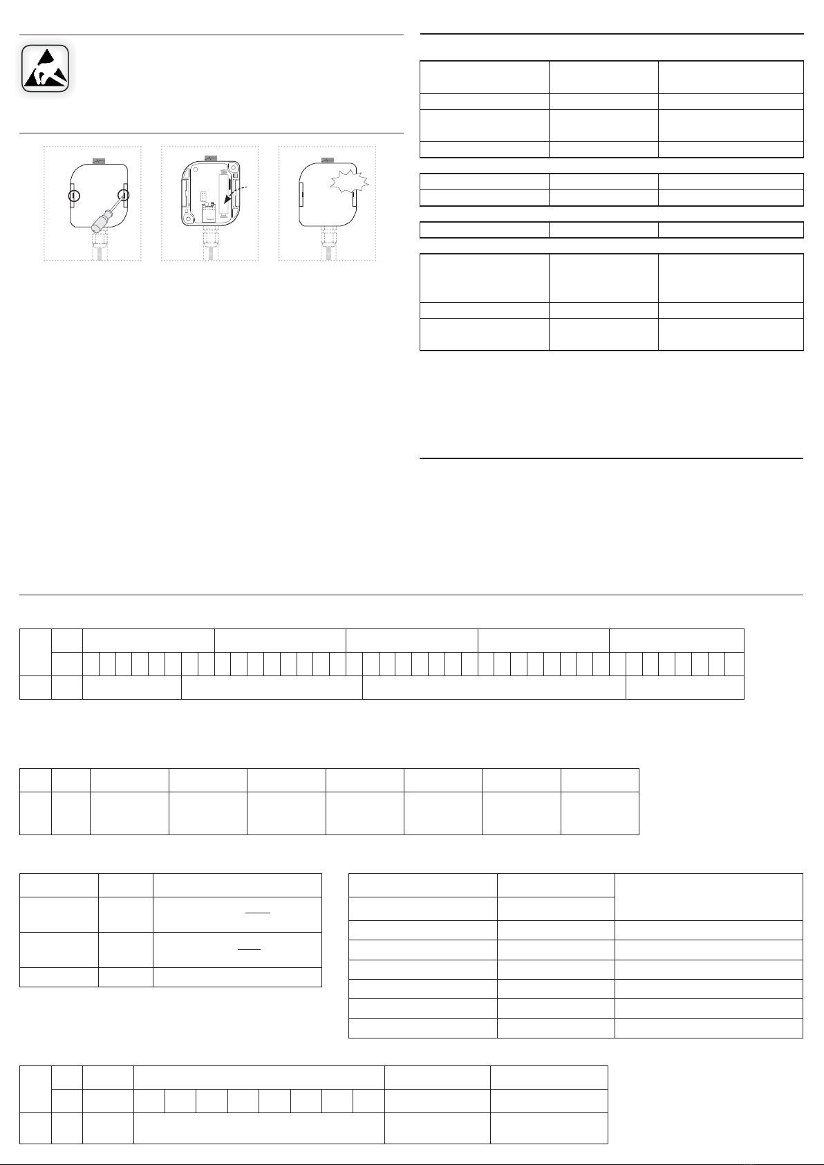
Replacing batteries
1. Using a at-blade screwdriver gradually slide it into one and then the other groove in
the lid and swing open the cover.
2. Remove the discharged battery and insert a new battery into the holder. Beware of
polarity. Both LEDs will ash 3 times (see device status indication).
3. Replace and snap the front cover.
Notice:
Only use batteries designed for this product correctly inserted in the device! Immediately replace
weak batteries with new ones. Do not use new and used batteries together. If necessary, clean the
battery and contacts prior to using. Avoid battery shorts! Do not dispose of batteries in water or
re. Do not dismantle batteries, do not try to charge them and protect them from extreme heating
- danger of leakage! Upon contact with acid, immediately rinse the aected area with a stream of
water and seek medical attention. Keep batteries out of the reach of children. If it is suspected that
the battery has been swallowed or somehow placed inside the body, consult a doctor immediately.
Give the doctor information about the type of battery (from battery case, device or its manual, etc.)
to determine the chemical composition of the battery. Batteries must be recycled or returned to an
appropriate location (e.g. collection container) in accordance with local legal provisions.
power supply (external or battery),
reset unit
Search availability BTS
error MAC / error MODULU
start unit ok
opening the cover
test
sending / receiving data
it is necessary to disconnect the power
supply (external or battery), after 60 seconds
after the LED goes out, insert the battery
the battery may be discharged
a discharged battery or a damaged
product
Unit initialization
Start
Search for BTS * 1)
SIM ERR *1)
ERR *1)
Successful network connection * 1)
Measurement
Tamper
SET button short press (< 2s)
Communication
Communication *1)
Other known states
Does not respond to the SET
button
The unit is still in reset
The unit does not respond even
after removal insert the battery
Indication
3 x R + G blinks
2 x ashes R (2xR _ 2xR _ ...)
5 x ashes R (repeatedly)
1 x ashes R
without indication
1 x ashes G
1 x ashes R
any LED lights
still indicates start
without indication
UPLINK / DOWNLINK
UPLINK
DOWNLINK
Note
Port01234567
1 0x09 Heartbeat
period
Measurement
period
Threshold
Temperature
dierence
Threshold
Soil resistance 1
Threshold
Soil resistance 2
Threshold
Temperature 1
Threshold
Temperature 2
Heartbeat period 0 - 127 [x min]
Heartbeat message period
128 - 255 [(x - 127) h]
Measurement period 1 - 255 [s] Measurement period for temperature
Threshold Temperature dierence 0 - 50 [°C] Threshold dierence for temperature
Threshold Soil resistance 1 0 - 65535 [Ω] Resistance point 1 for sending the message
Threshold Soil resistance 2 0 - 65535 [Ω] Resistance point 2 for sending the message
Threshold Temperature 1 -40 - 120 [°C] Threshold level 1 for temperature
Threshold Temperature 2 -40 - 120 [°C] Threshold level 2 for temperature
Port
Byte0123 4
Bit 765432107654321076543210765432107654321 0
1 Battery (B) Temperature (T) Soil resistance (R) Reserved
UPLINK
Port
Byte 0 1 2 3
Bit 76543210
3Version
FW Subversion FW Version FW
Narrowband
Subversion FW
Narrowband
Name Unit Example
Battery V Battery =
30 + B
10
Temperature °C Temperature = (
(T - 1)
211 - 1 x 165)- 40
Soil resistance Ω Resistance = R - 1
When handling a device unboxed it is important to avoid contact with
liquids. avoid unnecessary contact with the components of the device. Do
not touch the metal objects inside the unit.
Safe handling

4 / 4
AirSS-100L
Technical parameters Warning
* Values are calculated under ideal conditions
** Depending on network coverage
*** Without bushing / with bushing
Read the operating instructions before installing the device and putting it into opera-
tion. Instruction manual is designated for mounting and also for user of the device. It is
always a part of its packing. Installation and connection can be carried out only by a per-
son with adequate professional qualication upon understanding this instruction man-
ual and functions of the device, and while observing all valid regulations. Trouble-free
function of the device also depends on transportation, storing and handling. In case you
notice any sign of damage, deformation, malfunction or missing part, do not install this
device and return it to its seller. It is necessary to treat this product and its parts as elec-
tronic waste after its lifetime is terminated. Before starting installation, make sure that all
wires, connected parts or terminals are de-energized. While mounting and servicing ob-
serve safety regulations, norms, directives and professional, and export regulations for
working with electrical devices. Do not touch parts of the device that are energized – life
threat. To ensure the transmission of the radio signal, make sure that the devices in the
building where the installation is installed are correctly located. Unless otherwise stated,
the devices are not intended for installation in outdoor and damp areas, they must not
be installed in metal switchboards or in plastic cabinets with metal doors - this prevents
transmission of the radio frequency signal. iNELS Air is not recommended for control-
ling life-saving instruments or for controlling hazardous devices such as pumps, heaters
without thermostat, lifts, hoists, etc. - radio frequency transmission may be overshad-
owed by obstruction, interference, transmitter battery may be discharged etc., thereby
disabling the remote control.
Power supply
Battery power:
Battery life by frequency *:
1x 10 minutes
1x 60 minutes
1x 12 hours
1x 24 hours
Setting
Setting:
Battery status view:
Control
Control:
Sensor parameters
Humidity measuring range
Sensor stabilization in soil:
Communication
Protocol:
Transmitter frequency:
Range in open space:
Transmission power (max.):
Other parameters
Working temperature:
Storage temperature:
Device
Operation position:
Mounting:
Protection degree:
Dimension:
Sensor
Operation position:
Cord / Rod Length:
Weight:
1x 3.6V LS 14500 Li-SOCl2AA
7.1 years
10.6 years
11.7 years
11.8 years
Using a message from the server,
the programming cable
message to the server
button (Communication test)
Tamper
10-190 centibars
3 days after placement in soil
LoRa
868 MHz
Approx. 10 km**
25 mW / 14 dBm
-30…+60°C (Pay attention to the operating
temperature of batteries)
-30…+70°C
vertical, antenna up
glue / screws
IP65
110 / 136 x 62 x 34 mm***
vertical,
with the power cord / rod up
1 m
85 x Ø 22 mm
The company ELKO EP, as the manufacturer, is entitled to make technical modications to the product, in the technical specication and product manual, without prior notication.
Other Elko Measuring Instrument manuals


