manuals.online logo
Brands
  1. Home
  2. •
  3. Brands
  4. •
  5. Elmo
  6. •
  7. Controllers
  8. •
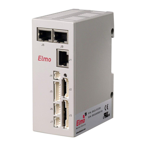
  9. Elmo Platinum Maestro User manual

Elmo Platinum Maestro User manual

Platinum Maestro
Network Motion Controller
Installation Guide
October 2018 (Ver. 1.008) www.elmomc.com
|Cautions|www.elmomc.com
Table of Contents
Notice
This guide is delivered subject to the following conditions and restrictions:
•
This guide contains proprietary information belonging to Elmo Motion Control Ltd. Such
information is supplied solely for the purpose of assisting users of the Platinum Maestro
motion controller in its installation.
•
The text and graphics included in this manual are for the purpose of illustration and
reference only. The specifications on which they are based are subject to change without
notice.
•
Information in this document is subject to change without notice.
Elmo Motion Control and the Elmo Motion Control logo are registered
trademarks of Elmo Motion Control Ltd.
EtherCAT®is a registered trademark and patented technology, licensed by
Beckhoff Automation GmbH, Germany.
CANopen compliant. CANopen®is a registered trademark and patented
technology, licensed by CAN in Automation (CiA) GmbH, Kontumazgarten
3, DE-90429 Nuremberg, Germany.
Document no. MAN-P-MAESTRO-IG (Ver. 1.008)
Copyright 2018
Elmo Motion Control Ltd.
All rights reserved.
Catalog Number
Table of Contents
MAN-P-MAESTRO-IG (Ver. 1.008)
|Cautions|www.elmomc.com
3
Table of Contents
Chapter 1: Safety Information ......................................................................................5
1.1 Cautions......................................................................................................................5
1.2 Directives and Standards............................................................................................5
1.3 Warranty Information ................................................................................................5
Chapter 2: Product Description.....................................................................................6
2.1 Description .................................................................................................................6
Chapter 3: Technical Specifications...............................................................................7
3.1 Processor System .......................................................................................................7
3.2 Communications.........................................................................................................7
3.3 Power Supply..............................................................................................................8
3.4 Physical Specifications................................................................................................8
3.5 General .......................................................................................................................8
3.6 Environmental Conditions..........................................................................................8
Chapter 4: Platinum Maestro Software Specifications ...................................................9
4.1 Operating System .......................................................................................................9
4.2 Axes ............................................................................................................................9
4.3 Motion Modes and Interfaces..................................................................................10
4.4 Drive Communication Bridge Support......................................................................11
4.5 General .....................................................................................................................11
4.6 Communication Options ..........................................................................................12
Chapter 5: How to Use this Guide ...............................................................................13
Chapter 6: Installation................................................................................................14
6.1 Environmental Conditions........................................................................................14
6.2 Unpacking the Components .....................................................................................14
6.3 Mounting the Platinum Maestro..............................................................................16
6.3.1 Wall Mount................................................................................................16
6.3.2 Surface Mount...........................................................................................16
Chapter 7: Wiring.......................................................................................................17
7.1 Connectors ...............................................................................................................17
7.1.1 Wiring the Platinum Maestro....................................................................17
7.1.2 Connector Types........................................................................................17
7.1.3 Power Connector.......................................................................................18
7.2 Connecting the DC Power Supply.............................................................................19
7.3 Status Indicator ........................................................................................................20
7.4 EtherCAT Status Indicator ........................................................................................20
7.5 EtherCAT Master Connectors...................................................................................21
Table of Contents
MAN-P-MAESTRO-IG (Ver. 1.008)
|Cautions|www.elmomc.com
4
Table of Contents
7.5.1 EtherCAT Master Port 1 Connector...........................................................21
7.5.2 EtherCAT Master Activity Indicators .........................................................22
7.5.3 EtherCAT Network.....................................................................................23
7.5.4 Ethernet Host Connectors .........................................................................24
7.5.4.1 Ethernet Host Activity Indicators..............................................25
7.5.5 Ethernet Communication ..........................................................................26
7.6 CAN Connectors .......................................................................................................27
7.7 USB 2.0 Type A .........................................................................................................29
7.8 Device USB 2.0 Type B..............................................................................................30
7.9 microSD™ Memory Card (Push-push Type) SCHA....................................................31
7.10 Powering Up .............................................................................................................32
7.11 Initializing the System ..............................................................................................32
Chapter 8: Platinum Maestro Dimensions ...................................................................33
Chapter 9: Compliance with Standards .......................................................................35
9.1 Low Voltage Directive...............................................................................................35
9.2 Other Compliant Standards......................................................................................35
Network Motion Controller Installation Guide
MAN-P-MAESTRO-IG (Ver. 1.008)
|Cautions|www.elmomc.com
5
Table of Contents
Chapter 1:
Safety Information
In order to achieve the optimum, safe operation of the Platinum Maestro Multi-Axis Controller, it is
imperative that you implement the safety procedures included in this installation guide. This
information is provided to protect you and to keep your work area safe when operating the
Platinum Maestro and accompanying equipment.
Please read this chapter carefully before you begin the installation process.
Before you start, ensure that all system components are connected to earth ground. Electrical
safety is provided through a low-resistance earth connection.
The following safety symbols are used in this manual:
Caution:
This information is necessary for preventing damage to the product or to other equipment.
1.1 Cautions
•
The Platinum Maestro must be connected to an approved 24 VDC power supply through a
line that is separated from hazardous line voltages using reinforced or double insulation in
accordance with approved safety standards.
•
Before switching on the Platinum Maestro, verify that all safety precautions have been
observed and that the installation procedures in this manual have been followed.
1.2 Directives and Standards
The Platinum Maestro conforms to the following industry standards:
Standard Item
In compliance with EN 60204-1 Low Voltage Directive 73/23/EEC
In compliance with CE 2006/95/EC Low-Voltage Directive 2006/95/EC
The Platinum Maestro has been developed, produced, tested and documented in accordance with
the relevant standards. Elmo Motion Control is not responsible for any deviation from the
configuration and installation described in this documentation. Furthermore, Elmo is not
responsible for the performance of new measurements or ensuring that regulatory requirements
are met.
1.3 Warranty Information
The products covered in this manual are warranted to be free of defects in material and
workmanship and conform to the specifications stated either within this document or in the
product catalog description. The Platinum Maestro is warranted for a period of 12 months from the
date of shipment. No other warranties, expressed or implied – and including a warranty of
merchantability and fitness for a particular purpose – extend beyond this warranty.
Network Motion Controller Installation Guide
MAN-P-MAESTRO-IG (Ver. 1.008)
|Description|www.elmomc.com
6
Table of Contents
Chapter 2:
Product Description
This installation guide describes the Platinum Maestro Network Motion Controller and the steps for
its wiring, installation and power up. Following these guidelines ensures maximum functionality of
the system to which it is connected.
2.1 Description
The Platinum Maestro is Elmo’s premium network motion controller. It works in a network based
system in conjunction with Elmo’s intelligent servo drives to provide a total multi-axis motion
control system solution.
The Platinum Maestro Motion Controller incorporates an integral high-level computational
dual-core system (2 x 1.5 GHz) with limitless memory (RAM, ROM, and SD-Card), and onboard
additional hardware peripherals.
The Platinum Maestro shares the motion processing workload with Elmo’s SimplIQ and Gold Line
drives, forming a distributed motion control system. The best servo and system performance is
achieved by combining the Gold Family drives, and the new real-time motion control capabilities of
the Platinum Maestro controller.
The Platinum Maestro provides:
•
Self-sufficient machine motion control – No reliance on connection with PC server
•
Time deterministic control over motion, I/Os and processes in the system
•
Complete compatibility with recognized networking and communications protocols
•
Full, real-time, multi-axis motion synchronization
•
Advanced user programming capabilities based on the leading standards
•
Unified development platform that streamlines motion control solutions for novice and
expert programmers alike
The Platinum Maestro offers real-time motion control support for full multi-axis system
synchronization, using the well-known industry interface PLCopen for Motion Control standard.
Various programming capabilities, such as the IEC-61131-3 standard languages, as well as native C
and C++ programming support, dramatically accelerate user-level program execution. Standard
solutions are selected for ease of use.
Low-level communication with drives and I/O devices over the device network uses the CAN
industry standard (DS 301, DS 401 for I/O devices, and DS 402 for drives and motion device
profiles). These are used over standard CAN networks, as well as with the new EtherCAT CoE (CAN
over EtherCAT) protocols.
Host interfaces are implemented using industry standard communications protocols, such as
Ethernet TCP/IP and higher level protocols such as Ethernet/IP and Modbus.
Standardization in protocols, definitions, and APIs allows users rapid system level integration and
opens the system to third party devices on the device network.
Network Motion Controller Installation Guide
MAN-P-MAESTRO-IG (Ver. 1.008)
|Processor System|www.elmomc.com
7
Table of Contents
Chapter 3:
Technical Specifications
3.1 Processor System
Feature Details
Processor Computational core system based on Dual Core (2×1.5 GHz)
On Board Flash 4 GByte
RAM DDR-3, 4 GByte, 64 bit bus width, (Operational at Full Core
Rate)
SD Card MicroSD™ Memory Card (Push-push Type) SCHA
3.2 Communications
Specification Details
Ethernet for Host 1 Ethernet port 1000 base-T
Automatically detected 10/100/1000Mbps
CAT5e/6 Cable
UDP, Telnet, TCP
EtherCAT Master Field bus 2 Ethernet port 100 base-T for EtherCAT Master.
Baud Rate: 100 Mbit/sec
CAT5e Cable
CoE, EoE, FoE
EtherCAT Master with Full redundancy support
CAN for device network 1 Port 1Mbps, with Isolation
CANopen master port
Maximum Baud Rate of 1 Mbits/sec.
CAN Profile:
DS 301
Device Profile (drive and motion control):
CAN device profiles, e.g., DS301, DS505, DS402, DS401 (for I/O)
USB - Type A Device USB: High-Speed (HS 480Mbps) USB 2.0
USB - Type B Device Device USB: High-Speed (HS 480Mbps) USB 2.0
Network Motion Controller Installation Guide
MAN-P-MAESTRO-IG (Ver. 1.008)
|Power Supply|www.elmomc.com
8
Table of Contents
3.3 Power Supply
Feature Details
Supply input voltage Single power supply, 12V to 31V
Supply input power Typical 7.5 W (Without video support)
3.4 Physical Specifications
Feature Details
Weight 410 g (14.5 oz)
Dimensions 150 mm x 105 mm x 28 mm (5.91" x 4.13" x 1.10")
Mounting Method (with adapter) Wall Mount (“Bookshelf”)
3.5 General
Feature Details
RTC Real Time Clock Option with 3V battery
Internal System BIT The Platinum Maestro supports internal hardware BIT
(Built-in-tests) procedures to check the system integrity
level on each power up
Diagnostic LEDs EtherCAT and Ethernet activity
3.6 Environmental Conditions
Feature Details
Ambient operating temperature 0 °C to 40 °C (32 °F to 104 °F)
Storage temperature -20 °C to +85 °C ( -4 °F to +185 °F)
Maximum non-condensing humidity 90%
Network Motion Controller Installation Guide
MAN-P-MAESTRO-IG (Ver. 1.008)
|Operating System|www.elmomc.com
9
Table of Contents
Chapter 4:
Platinum Maestro Software Specifications
4.1 Operating System
Feature Details
Linux Operating System With Elmo’s RT extension for real-time motion control support
Motion Programming and
Debugging
Native C Programming, running on the target CPU. Compiling and
debugging via the Eclipse IDE using GCC under Cygwin.
IEC 61131-3 with PLCopen Motion Library extension, using Elmo
IDE. The following languages are supported:
Structured text (ST), textual
Function block diagram (FBD), graphical
Ladder diagram (LD), graphical
Sequential function chart (SFC), has elements to organize
programs for sequential and parallel control processing.
4.2 Axes
Feature Details
Axes Up to 96 axes, allowing mixed single axis, multiple axis and
coordinated axes motions
Axis Types Intelligent Servo Drives (Elmo), supporting both the SimplIQ
and Gold lines
Operation in Numeric Control – NC - (real-time master
synchronization) as well as non-NC modes
DS 402 CoE for EtherCAT and standard DS 402 drives for
CANopen
Network Motion Controller Installation Guide
MAN-P-MAESTRO-IG (Ver. 1.008)
|Motion Modes and Interfaces|www.elmomc.com
10
Table of Contents
Feature Details
Control System Update Rate EtherCAT:
Cycle Simultaneous Update Rates:
≥ 250 µs for up to 16 axes
500 µs for 32 axes
1 mSec. for 64 axes
Cycle Jitter: < 1 µs, based on Master DC (Distributed Clock)
support, for the full network
CAN:
Cycle Update Rate ≥ 1 mSec. (CAN physical network limitations
only)
Cycle Jitter: < 100 µs for CAN Sync message initiation (actual
jitter dependent on the CAN network’s physical limitations)
4.3 Motion Modes and Interfaces
Feature Details
The Platinum Maestro
motion interfaces use
PLCopen Standard
64 bit, real-time, double precision profile calculations, allowing
full on-the-fly control over speed, acceleration, deceleration and
jerk
Complex motion schemes, including look-ahead optimizing of
trajectory speed calculations, for complex vector motions
Cyclic buffer for 1,000 function blocks (a buffer for 1,000 motion
segments). The cyclical buffer removes any practical limit on the
number of function blocks
Communication Protocols Host:
Ethernet TCP-IP/UDP for operational modes
Telnet communication for setup and configuration
USB: Using binary protocol (maintenance)
Application level: Ethernet-IP/Modbus
Device Network:
EtherCAT: CoE/EoE/FoE, supports distributed clock master
CAN: CANopen device profiles, e.g., DS 301, DS 305, DS 402,
DS 401 (I/O device profile)
Host and Internal Software
Interface
TCP/IP interface from Host Computer. Software Library is
provided for easy TCP/IP communication interface.
This version will also support Ethernet-IP and Modbus over the
TCP-IP.
Network Motion Controller Installation Guide
MAN-P-MAESTRO-IG (Ver. 1.008)
|Drive Communication Bridge Support|www.elmomc.com
11
Table of Contents
Feature Details
Internal Software libraries, for "C" user programs are provided,
to write user code running on the Platinum Maestro target
processor (native mode).
Data Recording 8 MB data recording
Up to 64 vectors can be recorded simultaneously.
Supports more than 10 advanced triggering options and real-
time scope capabilities
Very fast data upload using Ethernet
Upload/Download Support Firmware update support (Platinum Maestro and drives)
System resource files
Axis parameter files
4.4 Drive Communication Bridge Support
Feature Details
Communication The Platinum Maestro supports full communication with any
specific drive (EtherCAT and CAN) for the purpose of simple
tuning or configuration at the drive level, i.e. there is no need
for direct communication with the drive.
Spatial Position-Based Pulse
Generation
The Platinum Maestro supports spatial (along the path)
position-based pulse generation. This is a unique feature,
required for the generation of position-based events in 3D
scanning systems.
The Platinum Maestro system, with Elmo’s intelligent Gold
servo drives, can support single axis and spatial enhanced
position-based compare functions, resulting in trigger output
signals accurate to 1 encoder count along the trajectory path.
4.5 General
Feature Details
Network Encoders Supports master based motion on network encoders
Position Error Mapping Supports 1-D, 2-D, and 3-D position-based error mapping
compensation
Network Motion Controller Installation Guide
MAN-P-MAESTRO-IG (Ver. 1.008)
|Communication Options|www.elmomc.com
12
Table of Contents
4.6 Communication Options
The Platinum Maestro can communicate with a host PC either via a standard Ethernet port or
through USB using a binary protocol for maintenance.
The Platinum Maestro communicates with its network devices using either EtherCAT or CAN
networks.
Figure 1: The Platinum Maestro Network Connections
Network Motion Controller Installation Guide
MAN-P-MAESTRO-IG (Ver. 1.008)
|Communication Options|www.elmomc.com
13
Table of Contents
Chapter 5:
How to Use this Guide
This manual is part of a documentation set that can be used to set up and program the motion of
any machine whose motors are controlled by Elmo’s SimplIQ or Gold Line servo drives. When used
in conjunction with the Maestro Software Manual it describes everything needed to get the
Platinum Maestro up and running. Please read the safety instructions in the first chapter before
starting.
After you have successfully mounted and installed the Platinum Maestro we suggest that you read
the Platinum Maestro Software Manual. If you have not already done so, follow the instructions in
the Installation Guide that arrived with your servo drive, and install a drive. At least one drive needs
to be connected to the Platinum Maestro in order for it to function as a motion controller.
Network Motion Controller Installation Guide
MAN-P-MAESTRO-IG (Ver. 1.008)
|Environmental Conditions|www.elmomc.com
14
Table of Contents
Chapter 6:
Installation
6.1 Environmental Conditions
You can guarantee the safe operation of the Platinum Maestro by ensuring that it is installed in an
appropriate environment.
For safe operation of the Platinum Maestro make sure it is installed in an appropriate environment.
Feature Value
Ambient operating temperature 0 °C to 40 °C (32 °F to 104 °F)
Storage temperature -20 °C to +85 °C ( -4 °F to +185 °F)
Maximum non-condensing humidity 90%
Operating area atmosphere No flammable gases or vapors permitted in area
6.2 Unpacking the Components
Before you begin working with the Platinum Maestro system, verify that you have all of its
components, as follows:
•
The Platinum Maestro multi-axis motion controller
•
Platinum Maestro software which may be downloaded from www.elmomc.com
The Platinum Maestro is shipped in a cardboard box with Styrofoam protection.
To unpack the Platinum Maestro:
1. Carefully remove the Platinum Maestro from the box.
2. Check the Platinum Maestro to ensure that there is no visible damage to the instrument. If
any damage has occurred, report it immediately to the carrier that delivered your
controller.
3. To ensure that the Platinum Maestro you have unpacked is the appropriate type for your
requirements, locate the part number sticker on the side of the Platinum Maestro as shown
below.
The part number at the top gives the type designation.
4. Verify that the Platinum Maestro type is the one that you ordered.
5. Refer to the appropriate part number in the section Catalog Number at the beginning of the
installation guide.
Network Motion Controller Installation Guide
MAN-P-MAESTRO-IG (Ver. 1.008)
|Unpacking the Components|www.elmomc.com
15
Table of Contents
6. If you are using CAN networking, verify that you have CAN termination resistors (dongles),
illustrated below.
Network Motion Controller Installation Guide
MAN-P-MAESTRO-IG (Ver. 1.008)
|Mounting the Platinum Maestro|www.elmomc.com
16
Table of Contents
6.3 Mounting the Platinum Maestro
The Platinum Maestro has three mounting options:
•
Wall mount
•
Surface mount
6.3.1 Wall Mount
Two M4 round head screws, one through each opening in the heat sink, are used to mount the
Platinum Maestro (see the diagram below) on a wall.
Figure 2: Wall Mounting the Platinum Maestro
6.3.2 Surface Mount
Use four M4 round head screws, one through each opening in the heat sink to connect the Platinum
Maestro to a surface.
Figure 3: Surface Mounting the Platinum Maestro
Network Motion Controller Installation Guide
MAN-P-MAESTRO-IG (Ver. 1.008)
|Connectors|www.elmomc.com
17
Table of Contents
Chapter 7:
Wiring
7.1 Connectors
7.1.1 Wiring the Platinum Maestro
Once the Platinum Maestro is mounted, you are ready to wire the device. Proper wiring, grounding
and shielding are essential for ensuring safe, immune and optimal performance of the Platinum
Maestro.
•
Use shielded CAT5e/6 cables for Ethernet and EtherCAT communication.
•
After completing the wiring, carefully inspect all wires to ensure tightness, good solder
joints and general safety.
7.1.2 Connector Types
The Platinum Maestro has the following connectors:
Pins Type Function
Top Connector
3 Phoenix 3.81 mm Pitch Header
Power and ground
Front Connectors
MMC1 Micro SD Card SD Card
13 HDMI HDMI (dependent on the firmware version)
Type B - Device Device USB
Type A USB
8 RJ-45 Host EtherCAT
8 RJ-45 EtherCAT Master 1
Network Motion Controller Installation Guide
MAN-P-MAESTRO-IG (Ver. 1.008)
|Connectors|www.elmomc.com
18
Table of Contents
Pins Type Function
Bottom Connectors
8 RJ-45 CAN
8 RJ-45 CAN
Table 1: Connector Types
7.1.3 Power Connector
Pin Signal Function
PE PE Protective Earth
[-] VL- Power Supply Input Return
[+] VL+ Power Supply Input Positive
Connector Location Cable Connector
3-Pin 3.81 mm Pitch Phoenix Header
(MC 1.5/3-G-3.81)
3-Pin Phoenix Plug
(MC 1.5/3-ST-3.81)
Type Manufacturer & Part No. Mating Connector
3.81 mm pitch
Header and Plug
Phoenix Header
MC 1.5/3-G-3.81
Phoenix Plug (supplied)
MC 1.5/3-ST-3.81
Table 2: Platinum Maestro Power and Ground Connectors
Network Motion Controller Installation Guide
MAN-P-MAESTRO-IG (Ver. 1.008)
|Connecting the DC Power Supply|www.elmomc.com
19
Table of Contents
7.2 Connecting the DC Power Supply
The Platinum Maestro requires 7.5 W when turned on. Any isolated power supply that can supply
that power is acceptable. The supplied power must be within the rated voltage
range of 12 V to 32 V.
Connect the DC output from the power supply to the power input port on the Platinum Maestro
using the 3-pin power plug provided.
To connect the power supply:
•
Use a 24 AWG twisted pair shielded cable. The shield should have copper braid.
•
Before applying power, first verify the polarity of the connection (protected).
Figure 4: Power Supply Connection Diagram
Network Motion Controller Installation Guide
MAN-P-MAESTRO-IG (Ver. 1.008)
|Status Indicator|www.elmomc.com
20
Table of Contents
7.3 Status Indicator
Figure 5 shows the position of the red/green dual LED, which is used for immediate indication of the
Initiation and Working states.
Figure 5: Platinum Maestro Status Indicator
The red/green dual LED is used for immediate indication of the following states:
•
Initiation state: In this state the LED indicates whether the Maestro is in the boot state
(blinking red) or in the operational state (steady green).
•
Error state: In this state the LED indicates whether the motion controller is in error state
(blinking green).
7.4 EtherCAT Status Indicator
Figure 6: EtherCAT Status LEDs
The EtherCAT status indicator is a single red/green dual bi-colored LED that combines the green
RUN indicator and the red ERROR indicator of the EtherCAT state machine. For further details, see
the EtherCAT Application Manual.

This manual suits for next models

1

Other Elmo Controllers manuals

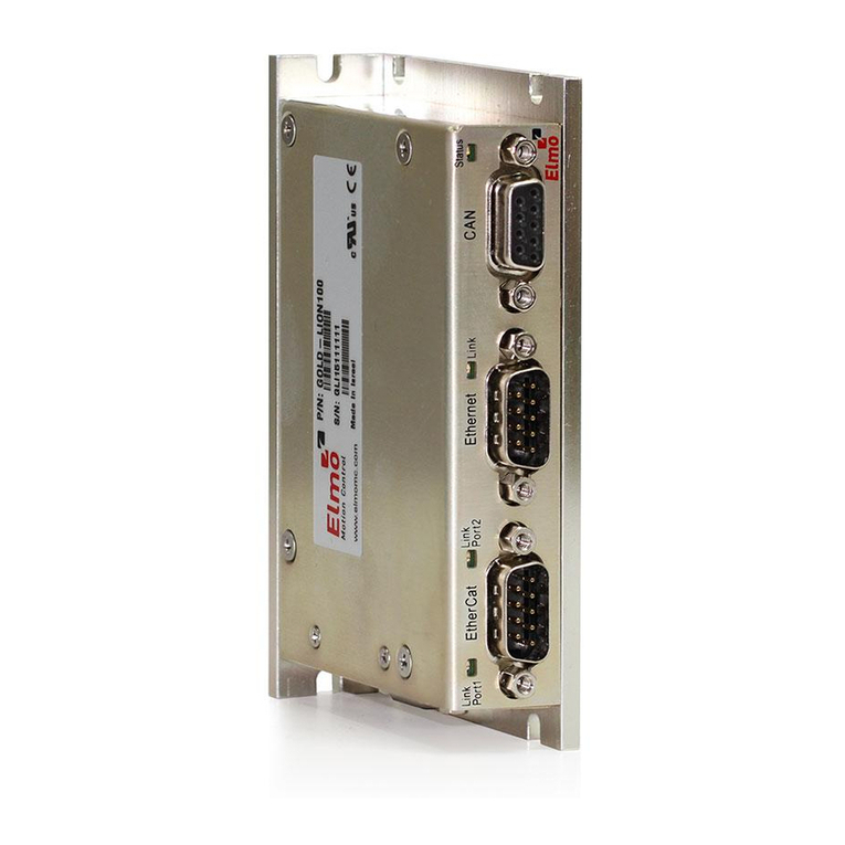
Elmo Gold Lion 100 User manual

Elmo

Elmo Gold Lion 100 User manual

Elmo VILLEGGIO NG-TRX Series User manual

Elmo

Elmo VILLEGGIO NG-TRX Series User manual

Elmo Gold Maestro G-MAS User manual

Elmo

Elmo Gold Maestro G-MAS User manual

Elmo ESD-CC1 User manual

Elmo

Elmo ESD-CC1 User manual

Elmo Bassoon User manual

Elmo

Elmo Bassoon User manual

Popular Controllers manuals by other brands

JSG A2 user guide

JSG

JSG A2 user guide

Chino DB600 Series instruction manual

Chino

Chino DB600 Series instruction manual

Regin XCA152W-4 manual

Regin

Regin XCA152W-4 manual

Samson TROVIS 5500 Mounting and operating instructions

Samson

Samson TROVIS 5500 Mounting and operating instructions

Warner Electric CBC-150 Series Installation and operation manual

Warner Electric

Warner Electric CBC-150 Series Installation and operation manual

Superfeed SC91T Operational manual

Superfeed

Superfeed SC91T Operational manual

DYS DWA-2000A-SS Operating instructions manual

DYS

DYS DWA-2000A-SS Operating instructions manual

Honeywell S9201A1010 quick start guide

Honeywell

Honeywell S9201A1010 quick start guide

PowerLed BLE-DIM instructions

PowerLed

PowerLed BLE-DIM instructions

Fubag MICRO 40/12 Operator's manual

Fubag

Fubag MICRO 40/12 Operator's manual

LIXiSE LXC63 0 Series user manual

LIXiSE

LIXiSE LXC63 0 Series user manual

ALLEN & HEATH PL Series user guide

ALLEN & HEATH

ALLEN & HEATH PL Series user guide

VAREL RXFM6 manual

VAREL

VAREL RXFM6 manual

Chemigem DM50 STARTING & OPERATING

Chemigem

Chemigem DM50 STARTING & OPERATING

LAE AR2-27 Instructions for use

LAE

LAE AR2-27 Instructions for use

Lutron Electronics Grafik Eye GRX-TVI Installation and operating instructions

Lutron Electronics

Lutron Electronics Grafik Eye GRX-TVI Installation and operating instructions

Jecod RW-4 user manual

Jecod

Jecod RW-4 user manual

Stryten Energy M Series Installation and operating instructions

Stryten Energy

Stryten Energy M Series Installation and operating instructions

manuals.online logo
manuals.online logoBrands
  • About & Mission
  • Contact us
  • Privacy Policy
  • Terms and Conditions

Copyright 2025 Manuals.Online. All Rights Reserved.