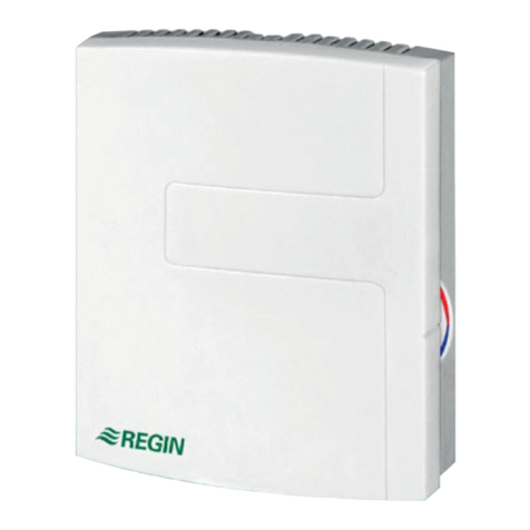
Regin XCA152W-4 User manual

en
WE TAKE BUILDING
AUTOMATION PERSONALLY
MANUAL
EXOCOMPACT ARDO, EEDO AND VIDO

Rev. B, 2020-01-14
THANK YOU FOR CHOOSING REGIN!
Ever since Regin was established in 1947, we have developed and marketed prod cts and systems that create good
levels of indoor comfort. Today, we are an important player with one of the market's broadest ranges for b ilding
a tomation.
O r goal is to make real estates in the world more energy efficient. Regin is an international gro p and o r prod cts
sells in over 90 co ntries. Thanks to o r global presence with strong local representation, we are well aware of the
req irements of the market, as well as of how o r prod cts and systems f nction nder the most variable conditions.
Every year, Regin makes s bstantial investments in the development of o r systems and HVAC-prod cts.
DISCLAIMER
The information in this man al has been caref lly checked and is believed to be correct. Regin makes no warranties
abo t the contents of this man al and sers are req ested to report errors and discrepancies to Regin, so that
corrections may be made in f t re editions. The information in this doc ment is s bject to change witho t prior
notification.
Some prod ct names mentioned in this doc ment are sed for identification p rposes only and may be the registered
trademarks of their respective companies.
© AB Regin. All rights reserved.

Table o Contents
1 Introduction .................................................................................................................................5
1.1 Abo t EXOcompact ...........................................................................................................5
1.2 Abo t this man al...............................................................................................................5
2 General in ormation.....................................................................................................................6
2.1 DIN rail mo nting inside a cabinet........................................................................................6
2.2 Maintenance and service ......................................................................................................6
2.2.1 Changing the battery..............................................................................................6
2.2.2 Changing the f se ..................................................................................................7
2.2.3 Resetting the application memory ...........................................................................7
2.3 Display ..............................................................................................................................8
2.4 Installation recommendations...............................................................................................9
3 EXOcompact Ardo....................................................................................................................10
3.1 Stat s indications ..............................................................................................................10
3.1.1 XCA203…-4 ......................................................................................................10
3.2 Terminals and wiring diagram ............................................................................................11
3.2.1 Model XCA203W-4 ............................................................................................11
3.2.2 Models XCA…-4.................................................................................................14
4 EXOcompact Eedo....................................................................................................................17
4.1 Stat s indications ..............................................................................................................17
4.2 Terminals and wiring diagram ............................................................................................17
4.2.1 Models XCE…W-1..............................................................................................17
5 EXOcompact Vido ....................................................................................................................20
5.1 Stat s indications ..............................................................................................................20
5.2 Terminals and wiring diagram ............................................................................................20
5.2.1 Models XCV193…-2...........................................................................................20
Appendix A Technical data..........................................................................................................22
A.1 EXOcompact Ardo ...........................................................................................................22
A.1.1 General data........................................................................................................22
A.1.2 Inp ts & O tp ts.................................................................................................22
A.1.3 Comm nication ports ..........................................................................................22
A.1.4 Serial ports..........................................................................................................22
A.1.5 Ethernet port ......................................................................................................23
A.1.6 M-B s port..........................................................................................................23
A.1.7 HMI ...................................................................................................................23
A.1.8 Material..............................................................................................................23
A.2 EXOcompact Eedo ...........................................................................................................23
A.2.1 General data........................................................................................................23
A.2.2 Inp ts & O tp ts.................................................................................................24
A.2.3 Comm nication ports ..........................................................................................24
A.2.4 Serial ports..........................................................................................................24
A.2.5 Ethernet port ......................................................................................................24
A.2.6 Material..............................................................................................................24
A.3 EXOcompact Vido ...........................................................................................................24
A.3.1 General data........................................................................................................24
A.3.2 Inp ts & O tp ts.................................................................................................25
A.3.3 Comm nication ports ..........................................................................................25
A.3.4 Serial ports..........................................................................................................25
A.3.5 Ethernet port ......................................................................................................25
A.3.6 M-B s port..........................................................................................................26
A.3.7 Material..............................................................................................................26

Table o Contents
Appendix B Model overview .......................................................................................................27
B.1 EXOcompact Ardo ...........................................................................................................27
B.2 EXOcompact Eedo ...........................................................................................................27
B.3 EXOcompact Vido ...........................................................................................................27

Introduction
1 Introduction
1.1 About EXOcompact
EXOcompact is Regin's family name for compact and freely programmable controllers. These controllers
provides b ilt-in comm nication via EXOline, Modb s or BACnet and can be sed either as stand-alone or
for integration into EXOscada or other SCADA systems. User-friendly tools are available for flexible
handling and easy access via the web server.
C rrently three general models are available, i.e. EXOcompact Ardo, EXOcompact Eedo and EXOcompact
Vido.
1.2 About this manual
This man al provides descriptions of the EXOcompact Ardo, Eedo and Vido hardware-related information
concerning controller connections, wiring, mo nting, maintenance and service, and so on.
All models are config red and commissioned by sing Regin's EXOdesigner software, which is described in
depth in EXOhelp.
Special text formats sed in the man al:
NNoottee!! This box and symbol is used to show use ul tips and tricks.
WWaarrnniinngg!! This type o text and symbol is used to show warnings.
EXOcompact Ardo, Eedo and Vido manual, Rev.
B5

General in ormation
2 General in ormation
2.1 DIN rail mounting inside a cabinet
To mo nt the controller:
1. P ll o t the fastener.
2. Attach the controller to the rail.
3. P sh in the fastener to sec re the controller.
Figure 2-1 Attaching the controller to the DIN rail.
2.2 Maintenance and service
WWaarrnniinngg!! Be ore installation or maintenance, the power supply must irst be disconnected in order to
prevent potentially lethal electric shocks! Installation or maintenance o this unit should only be carried
out by quali ied personnel. The manu acturer is not responsible or any eventual damage or injury
caused by inadequate skills during installation, or through removal o or deactivation o any security
devices.
2.2.1 Changing the battery
WWaarrnniinngg!! To prevent electric shock, the controller must be disconnected rom power be ore the
battery is changed.
To change the battery:
1. Disconnect the controller from power, and then remove the terminal protection covers (if wall
mo nted).
6EXOcompact Ardo, Eedo and Vido manual, Rev.
B

General in ormation
2. Remove the top of the casing by pressing the two tabs on each side of the casing, and then lift p the
top of the casing caref lly.
Figure 2-2 Removing the top of the casing.
3. Change the battery. A lithi m CR2032 battery is sed.
4. Assemble the casing caref lly again.
5. Wire the controller, attach the terminal protection covers (if wall mo nted), and then power p the
controller.
2.2.2 Changing the use
WWaarrnniinngg!! To prevent electric shock, the controller must be disconnected rom power be ore the use
is changed.
To change the f se:
1. Disconnect the controller from power, and then remove the terminal protection covers (if wall
mo nted).
2. Remove the top of the casing by pressing the two tabs on each side of the casing, see Figure 2-2, and
then lift p the top of the casing caref lly.
3. Change the f se. A 6.3 AT 5x20 mm f se is sed.
4. Assemble the casing caref lly again.
5. Wire the controller, attach the terminal protection covers (if wall mo nted), and then power p the
controller.
2.2.3 Resetting the application memory
WWaarrnniinngg!! This procedure should only be carried out by quali ied personnel, since it requires advanced
knowledge. The current application will stop running and the controller will return to its de ault settings
which may damage the system.
The controller is reset by pressing the reset b tton on the side of the casing (at the bottom for EXOcompact
Vido) by sing something thin, s ch as a paper clip. After a reset, the controller starts p again with factory
settings applied.
EXOcompact Ardo, Eedo and Vido manual, Rev.
B7

General in ormation
Figure 2-3 Resetting the application memory.
2.3 Display
The display has 4 rows of 20 characters each. It has backgro nd ill mination. The ill mination is normally
off, b t is activated as soon as a b tton is pressed. The ill mination will be t rned off again after a period of
inactivity.
There are two LEDs on the front:
✓The red LED is sed for alarm indication and is marked with the symbol
✓The green LED is sed for write indication and is marked with the symbol
The display men system is handled sing seven b ttons as shown in Table 2-1.
Table 2-1 ummary of the function of the buttons
The buttons Functions Function in Alarm Mode
[▲][▼][►][◄] Navigation buttons:
▲ Navigate upwards.
▼ Navigate downwards.
► Navigate to the right.
◄ Navigate to the left.
In change mode:
◄ Move cursor to the left.
► Move cursor to the right.
▲ Increase the value by 1.
▼ Decrease the value by 1.
▲and ▼ Scroll among the texts when
there are several alternatives.
▲ Navigate up in the alarm stack.
▼ Navigate down in the alarm stack.
◄ Exit alarm display mode.
[OK] ✓Enter change mode.
✓Confirm a new value in change mode.
An input must be confirmed with this
button in order to change the value in
the controller.
When a value has been confirmed, the
cursor will move to the next manoeu-
vrable value in the current box.
✓A menu with all available maneuvers
that are available for the current alarm is
displayed.
8EXOcompact Ardo, Eedo and Vido manual, Rev.
B

General in ormation
Table 2-1 ummary of the function of the buttons (continued)
The buttons Functions Function in Alarm Mode
[C] ✓Enter change mode and erase the value
in the display.
✓Erase the sign at the cursor.
✓When the current value is completely
empty, the maneuver mode is cancelled
and the cursor will move to the next
value that will also be erased in the
window.
✓Undo (erase) the input
✓Closes the menu containing available
alarm manoeuvres without changing the
state of the alarm point.
[ALARM] ✓Enter alarm display mode. ✓Browse among alarms in alarm display
mode.
All EXOcompact controllers have a q ick connection for an external display. The maxim m permitted cable
length for an external display is 100 m.
2.4 Installation recommendations
Follow these g idelines regarding shielded cables:
✓Only se shielded cables when the installation environment req ires it.
✓No need for shielded cables between mod les, if installed in close proximity
✓Connect shield to chassis gro nd at only one end of the cable.
For RS485 comm nication, the terminal Nis only req ired between systems not sharing the same gro nd
potential. When sed, do not connect it to the cable screen. Note that it may be a single wire, b t m st be
drawn together.
When the cable length is less than 30 m in RS485, a terminator is not req ired in normal cases. The se of
terminators will decrease signal integrity th s try witho t first. When sed, match the terminator val e to
the characteristic impedance of the cable.
Wiring examples can be fo nd nder each specific EXOcompact Ardo, Eedo and Vido model in the
following chapters.
EXOcompact Ardo, Eedo and Vido manual, Rev.
B9

EXOcompact Ardo
3 EXOcompact Ardo
3.1 Status indications
3.1.1 XCA203…-4
A LED is located at the top of the controller cassette and provides information abo t the controller stat s
and behavio r.
LED colour Description
Green, solid Power on and communication is established
Red, solid Battery problem
Yellow, blink 2.5 Hz Identification (wink)
Orange, blink 1 Hz IO-board is not in contact with CPU-board (via EFX)
The pper left corner of the controller contains a stat s indication. Alarm indications are shown in the
display
LED LED behaviour Description
P1 RxTx Yellow/ Green Port 1: Receiving/transmitting P2
P2 RxTx Yellow/ Green Port 2: Receiving/transmitting
TCP/IP Green/ Yellow Fixed green: Link
Flashing green: Traffic
Flashing yellow: Identification
P/B Green/ Red Power supply/Low battery level
10 EXOcompact Ardo, Eedo and Vido manual, Rev.
B

EXOcompact Ardo
3.2 Terminals and wiring diagram
3.2.1 Model XCA203W-4
The controller terminals are shown in Figure 3-1 and described in Table 3-1.
Figure 3-1 XCA203W-4 controller terminals layout
NNoottee!! This model can only be connected to 24 V AC, not DC.
Table 3-1 XCA203W-4 controller connection descriptions.
Terminal № and
designator
Type Description
1 G Supply voltage 24 V AC supply voltage.
2 G0 Supply voltage (reference) 24 V AC supply voltage (reference).
Ground Earth ground.
10 GDO
14 GDO
Supply voltage output 24 V AC supply voltage output for use together with digital outputs.
EXOcompactArdo
3
25 AI4a
30 AGND
1 G
2 G0
10 GDO
11 DO1b
12 DO2b
14 GDO
15 DO4b
16 DO5b
17 DO6b
13 DO3b
20 AGND
21 AI1a
22 AI2a
23 AGND
24 AI3a
31 CI1a
32 CI2a
AO1a 40
AO2a 41
AO3a 42
AO4a 43
AGND 45
GND 50
DI1b 51
DI2b 52
GND 53
DI3b 54
DI4b 55
E60
N61
A62
B63
N71
A72
B73
E70
{
P
1
{
P
2
EXOcompact Ardo, Eedo and Vido manual, Rev.
B11

EXOcompact Ardo
Table 3-1 XCA203W-4 controller connection descriptions. (continued)
Terminal № and
designator
Type Description
11 DO1b
12 DO2b
13 DO3b
15 DO4b
16 DO5b
17 DO6b
Digital output b Mosfet output used for e.g. valve, 3-speed fan, blinds, or lighting control, or for
alarms or forced ventilation.
20 AGND
23 AGND
30 AGND
45 AGND
Analog ground Signal ground for analog inputs and outputs.
21 AI1a
22 AI2a
24 AI3a
25 AI4a
Analog input a Input used for e.g. change-over detection or for temperature, CO2, condensa-
tion, or relative humidity sensor.
31 CI1a
32 CI2a
Condensation input a Input dedicated for Regin’s condensation detector KG-A/1.
Ethernet communication port 8P8C modular connector used for Ethernet - TCP/IP communication.
40 AO1a
41 AO2a
42 AO3a
43 AO4a
Analog output a Output used for e.g. valve, damper, or EC fan control.
50 GND
53 GND
Digital ground Signal ground for digital inputs.
51 DI1b
52 DI2b
54 DI3b
55 DI4b
Digital input b Input used for e.g. presence, open window, or change-over detection.
Ext. Disp. External display communica-
tion port
4P4C modular connector used for communication with an ED-RU-... room
unit.
60 E
61 N
62 A
63 B
RS485 communication port RS485 connector used for communication via BACnet, or for master/slave
communication via Exoline or Modbus.
This connection is not galvanically isolated.
70 E
71 N
72 A
73 B
RS485 communication port RS485 connector used for communication via BACnet, or for master/slave
communication via Exoline or Modbus.
This connection is galvanically isolated.
12 EXOcompact Ardo, Eedo and Vido manual, Rev.
B

EXOcompact Ardo
The wiring diagram in Figure 3-2 exemplifies controller connections sage.
Figure 3-2 XCA203… wiring diagram exemplifying controller connections usage.
Ardo
G0 | -
1
2
G | +
3
24 V AC
DO6b
DO5b
DO4b
GDO
DO3b
DO2b
DO1b
10GDO
11
12
13
14
15
16
17
Agnd
AO4a
AO3a
AO2a
AO1a
45
43
42
41
40
DI4b
DI3b
GND
DI2b
DI1b
GND
55
54
53
52
51
50
AI4a
AI3a
Agnd
AI2a
AI1a
20Agnd
21
22
23
24
25
CI2a
CI1a
30Agnd
31
32
Ext.
Disp.
Ethernet
(COM-) A
(COM+) B
N
63
62
61
{
P2
E60
(COM-) A
(COM+) B
N
73
72
71
P1
E70
{
Room unit
EDSP-K3
°C
PT1000
KG-A/1GND
0...10 V
N
L
G0
0...10 V
G
CTRTA
EXOcompact Ardo, Eedo and Vido manual, Rev.
B13

EXOcompact Ardo
3.2.2 Models XCA…-4
The controller terminals are shown in Figure 3-3 and described in Table 3-2.
Figure 3-3 XCA283W-4 controller terminals layout
{
P
1
B 50
A 51
N 52
E 53
EXOcompactArdo
3
41 UI1a
35 AI4a
43 AGND
1 G
2 G0
4 +C
10 GDO
11 DO1b
12 DO2b
14 DO4b
15 DO5b
16 DO6b
17 DO7b
DI2a 72
P/B
TCP/IP
P2 RxTx
13 DO3b
30 AGND
31 AI1a
32 AI2a
33 AGND
34 AI3a
40 AGND
42 UI2a
44 UI3a
P1 RxTx
45 UI4a
AO5a 95
AO4a 94
AO3a 93
AO2a 92
AO1a 91
AGND 90
DI8a 78
DI7a 77
DI6a 76
DI5a 75
DI4a 74
DI3a 73
DI1a 71
{
P
2
B 60
A 61
N 62
E 63
14 EXOcompact Ardo, Eedo and Vido manual, Rev.
B

EXOcompact Ardo
Table 3-2 XCA…-4 controller terminals descriptions
Terminal № and
designator
Type Description
1 G Supply voltage 24 V AC supply voltage.
2 G0 Supply voltage (reference) 24 V AC supply voltage (reference).
Ground Earth ground.
4 +C +24 V DC, reference for DI
10 GDO
14 GDO
Digital ground Signal ground for digital outputs DO.
11 DO1b
12 DO2b
13 DO3b
14 DO4b
15 DO5b
16 DO6b
17 DO7b
Digital output b Mosfet output used for e.g. valve, 3-speed fan, blinds, or lighting control, or for
alarms or forced ventilation.
30 AGND
33 AGND
40 AGND
43 AGND
90 AGND
Analog ground Signal ground for AI and AO.
31 AI1a
32 AI2a
34 AI3a
35 AI4a
Analog input a Input used for e.g. change-over detection or for temperature, CO2, condensa-
tion, or relative humidity sensor.
41 UI1a
42 UI2a
44 UI3a
45 UI4a
Universal input a
Ethernet communication port 8P8C modular connector used for Ethernet - TCP/IP communication.
50 B
51 A
52 N
53 E
RS485 communication port RS485 connector used for communication via BACnet, or for master/slave
communication via Exoline or Modbus.
This connection is galvanically isolated.
60 B
61 A
62 N
63 E
RS485 communication port 2 RS485 connector used for communication via BACnet, or for master/slave
communication via Exoline or Modbus.
This connection is not galvanically isolated.
Ext. Disp. External display communica-
tion port
4P4C modular connector used for communication with an ED-RU-... room
unit.
71 DI1a
72 DI2a
73 DI3a
74 DI4a
75 DI4a
76 DI4a
77 DI4a
78 DI4a
Digital input a Input used for e.g. presence, open window, or change-over detection.
91 AO1a
92 AO2a
93 AO3a
94 AO4a
95 AO5a
Analog output a Output used for e.g. valve, damper, or EC fan control.
The wiring diagram in Figure 3-4 exemplifies controller terminal sage.
NNoottee!! For models with M-Bus communication, port 2 is replaced by an M-Bus port.
EXOcompact Ardo, Eedo and Vido manual, Rev.
B15

EXOcompact Eedo
4 EXOcompact Eedo
4.1 Status indications
A LED is located at the top of the controller cassette and provides information abo t the controller stat s
and behavio r.
LED colour Description
Green, solid Power is on and all is O.
Red, solid Battery problem
Yellow, blink 2.5 Hz Identification (wink)
Orange, blink 1 Hz IO-board is not in contact with CPU-board (via EFX)
4.2 Terminals and wiring diagram
4.2.1 Models XCE…W-1
The controller terminals are shown in Figure 4-1 and described in Table 4-1.
Figure 4-1 XCE163W-1 controller terminals layout
EXOcompact Ardo, Eedo and Vido manual, Rev.
B17

EXOcompact Eedo
Table 4-1 XCE…W-1 controller terminals descriptions
Terminal № and
designator
Type Description
1 L Supply voltage 230 V AC supply voltage
2 N Supply voltage (neutral) 230 V AC supply voltage (neutral)
10 N1
12 N2
20 N3-5
Neutral Digital output neutral
11 DO1d
13 DO2d
Digital output d Triac output used for e.g. valve, blinds, or lighting control, or for alarms or
forced ventilation
21 DO3c
22 DO4c
23 DO5c
Digital output c Relay output used for e.g. 3-speed fan control
30 N
31 A
32 B
RS485 communication port 1 RS485 connector used for communication via BACnet, or for master/slave
communication via Exoline or Modbus.
This connection is galvanically isolated.
40 N
41 A
42 B
RS485 communication port 2 RS485 connector used for communication via BACnet, or for master/slave
communication via Exoline or Modbus.
This connection is not galvanically isolated.
Ext. Disp. External display communica-
tion port
4P4C modular connector used for communication with an ED-RU-... room unit
Ethernet communication port 8P8C modular connector used for Ethernet - TCP/IP communication
50 AGND
52 AGND
54 AGND
70 AGND
72 AGND
74 AGND
76 AGND
Analog ground Signal ground for analog inputs and outputs
51 AI1c Analog input c Input used for e.g. change-over detection or for temperature sensor
53 AI2b
55 AI3b
Analog input b Input used for e.g. CO2, condensation, or relative humidity sensor
56 POa Power output a 24 V DC supply voltage output e.g used for powering a CO2or condensation
sensor
60 GND
62 GND
64 GND
66 GND
Digital ground Signal ground for digital inputs
61 DI1b
63 DI2b
65 DI3b
Digital input b Input used for e.g. presence, open window, or change-over detection
67 CI1a Condensation input a Input dedicated for Regin’s condensation detector KG-A/1
71 AO1a
73 AO2a
75 AO3a
77 AO4a
Analog output a Output used for e.g. valve, damper, or EC fan control
18 EXOcompact Ardo, Eedo and Vido manual, Rev.
B

EXOcompact Eedo
The wiring diagram in Figure 4-2 exemplifies controller terminal sage.
Figure 4-2 Wiring diagram exemplifying controller terminals usage
Eedo
230 V AC
N | -
L | +
1
2
+24 V DC | POa56
230 V AC
DO5c
DO4c
DO3c
N3-5
DO2d
N2
DO1d
10N1
11
12
13
20
21
22
23
AO4a
AGND
AO3a
AGND
AO2a
AGND
77
76
75
AO1a
AGND
74
73
72
71
70
DI3b
GND
DI2b
GND
DI1b
GND
GND
CI1a67
66
65
64
63
62
61
60
AGND
AI1c
AGND
AI2b
AGND
AI3b55
54
53
52
51
50
Ext.
Disp.
Ethernet
A (COM-)
B (COM+)
N
40
41
42
{
P2
A (COM-)
B (COM+)
N
30
31
32
{
P1
ED-RU-...
EDSP-K3
M
I
III
II
°C
PT1000
KG-A/1
GND
0...10 V
N
L
G0
0...10 V
G
CTRTA
EXOcompact Ardo, Eedo and Vido manual, Rev.
B19

EXOcompact Vido
5 EXOcompact Vido
5.1 Status indications
No stat s indications are available for this model.
5.2 Terminals and wiring diagram
5.2.1 Models XCV193…-2
NNoottee!! Analogue inputs, digital inputs and universal analogue I/O:s must re er to a signal ground
terminal.
Table 5-1 XCV193…-2 controller terminals descriptions
Terminal № and
designator
Type Description
1 DO1 Digital output Output terminal DO1
2 Power supply Used for power supply to the digital outputs DO1 and DO2
3 DO2 Digital output Output terminal DO2
4Not used
5 DO3 Digital output Output terminal DO3
6 Power supply Used for power supply to the digital outputs DO3 and DO4
7 DO4 Digital output Output terminal DO4
8Not used
9 DO5 Digital output Output terminal DO5
10 Power supply Used for power supply to the digital outputs DO5 and DO6
View of terminal base
L
N
N
2
3
4
5
6
7
8
9
10
11
12
13
14
15
17
16
18
19
20
21
22
23
24
25
26
27
28
29
30
31
32
0..10V In/Out
1
8x PT1000
µ 1A 230V~ (ind.)
TCP/IP
ext.
Display
P1
BAE
AI1
AI2
AI3
AI4
AI5
AI6
AI7
AI8
DI1
DI2
UA1
UA2
Gnd
DO7
DO6
DO5
DO4
DO3
DO2
DO1
N
MBUS*
B
A
* Depending on the model
0..10V In/Out
20 EXOcompact Ardo, Eedo and Vido manual, Rev.
B
This manual suits for next models
10
Table of contents
Other Regin Controllers manuals

Regin
Regin RVA10-24A User manual

Regin
Regin Optigo OP5U User manual

Regin
Regin CORRIGO L10 User manual

Regin
Regin AQM2000A-1R User manual

Regin
Regin RVASN08 User manual

Regin
Regin RCF-230CTD-EC User manual

Regin
Regin PCMTV50-F20 User manual

Regin
Regin OPTIGO OP10 User manual

Regin
Regin RDAS-24C Series User manual

Regin
Regin TTC 2000 User manual

Regin
Regin RVAZ4L1-24 User manual

Regin
Regin RVAN18-24 User manual

Regin
Regin EXOCLEVER EC-PU4-2 User manual

Regin
Regin TTC25X User manual

Regin
Regin TTC40FX User manual

Regin
Regin REGIO RC-DTO User manual

Regin
Regin REGIO RC-T User manual

Regin
Regin TTC40F User manual

Regin
Regin REGIO ARDO User manual

Regin
Regin RVAB4-24 User manual