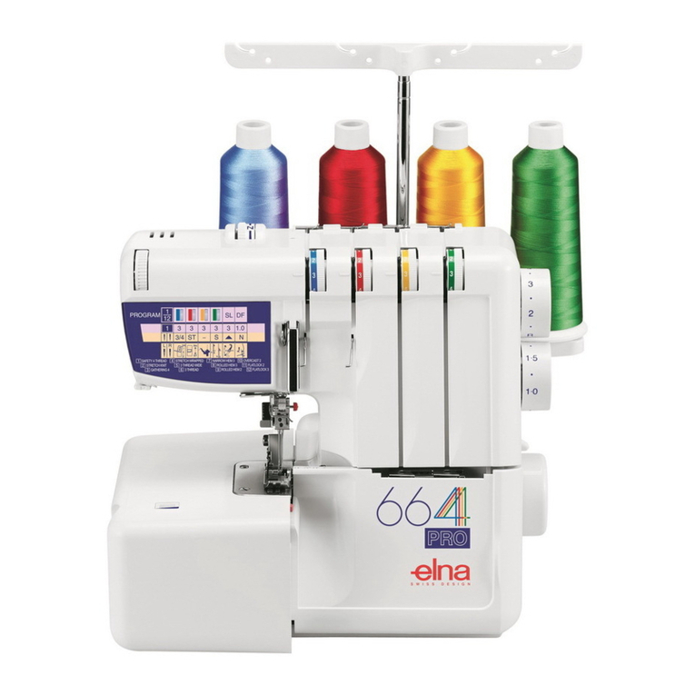
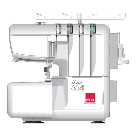
ELNA eXtend covermax User manual

eXtend covermax
| Instruction Manual |

IMPORTANT SAFETY INSTRUCTIONS
When using an electrical appliance, basic safety precautions should always be followed, including the
following:
This sewing machine is designed and manufactured for household use only.
Read all instructions before using this sewing machine.
DANGER— To reduce the risk of electric shock:
1. An appliance should never be left unattended when plugged in. Always unplug
this sewing machine from the electric outlet immediately after using and before
cleaning.
WARNING— To reduce the risk of burns, re, electric shock, or injury to persons:
1. Do not allow to be used as a toy. Close attention is necessary when this sewing machine is used
by or near children.
2. Use this appliance only for its intended use as described in this owner’s manual.
Use only attachments recommended by the manufacturer as contained in this owner’s manual.
3. Never operate this sewing machine if it has a damaged cord or plug, if it is not working properly, if
it has been dropped or damaged, or dropped into water.
Return this sewing machine to the nearest authorized dealer or service center for examination,
repair, electrical or mechanical adjustment.
4. Never operate the appliance with any air opening blocked. Keep ventilation openings of this
sewing machine and foot controller free from accumulation of lint, dust and loose cloth.
5. Never drop or insert any object into any opening.
6. Do not use outdoors.
7. Do not operate where aerosol (spray) products are being used or where oxygen is being
administered.
8. To disconnect, turn all controls to the off (“O”) position, then remove plug from outlet.
9. Do not unplug by pulling on cord. To unplug, grasp the plug, not the cord.
10. Keep ngers away from all moving parts. Special care is required around the sewing machine
needle and/or cutting blade.
11. Always use the proper needle plate. The wrong plate can cause the needle to break.
12. Do not use bent needles.
13. Do not pull or push fabric while stitching. It may deect the needle causing it to break.
14. Switch this sewing machine off (“O”) when making any adjustment in the needle area, such as
threading the needle, changing the needle, threading the bobbin or changing the presser foot, and
the like.
15. Always unplug this sewing machine from the electrical outlet when removing covers, lubricating, or
when making any other adjustments mentioned in this owner’s manual.
Please note that on disposal, this product must be safely recycled in accordance with relevant
National legislation relating to electrical/electronic products. If in doubt please contact your
retailer for guidance. (European Union only)
For Europe only:
This appliance can be used by children aged from 8 years and above and persons with reduced
physical, sensory or mental capabilities or lack of experience and knowledge if they have been given
supervision or instruction concerning use of the appliance in a safe way and understand the hazards
involved. Children shall not play with the appliance. Cleaning and user maintenance shall not be
made by children without supervision.
For outside Europe (except U.S.A.):
This appliance is not intended for use by persons (including children) with reduced physical, sensory
or mental capabilities, or lack of experience and knowledge, unless they have been given supervision
or instruction concerning use of the appliance by a person responsible for their safety.
Children should be supervised to ensure that they do not play with the appliance.
SAVE THESE INSTRUCTIONS
1
TABLE OF CONTENTS
ESSENTIAL PARTS
Names of Parts................................................................2
Standard Accessories......................................................3
GETTING READY TO SEW
Connecting the Machine to the Power Supply.................4
Controlling Sewing Speed ...............................................4
How to Turn the Handwheel ............................................ 5
Opening and Closing the Looper Cover ..........................5
Extension Table ...............................................................5
Retractable Sewing Light.................................................6
Presser Foot Lifter...........................................................6
Replacing the Presser Foot.............................................7
Adjusting the Presser Foot Pressure............................... 8
Adjusting the Stitch Length..............................................8
Adjusting the Differential Feed Ratio...............................8
Adjusting the Thread Tension ..........................................9
Changing Needle........................................................... 10
Setting the Thread Guide Bar........................................ 11
Setting the Spools ......................................................... 11
Threading the Machine.................................................. 12
Threading the Looper .................................................... 13
Threading the Needles .................................................. 16
Built-in Needle Threader................................................ 19
Handy Needle Threader ................................................ 21
Threading the Top Cover Stitch Guides and Spreader..22
STITCH TYPES AND TENSION SETTINGS
Top Cover Stitch ............................................................ 26
Balancing the thread tension....................................... 27
Triple Cover Stitch .........................................................28
Balancing the thread tension....................................... 28
Cover Stitch...................................................................29
Balancing the thread tension....................................... 30
Chain Stitch ................................................................... 31
Balancing the thread tension....................................... 31
Stitch and Thread Tension Chart ...................................32
Standard to Heavy fabrics ...........................................32
Fine fabrics.................................................................. 33
Beginning and End of the Seam....................................34
Beginning of the seam.................................................34
End of the seam with thread chain ..............................35
End of the seam without thread chain .........................36
Beginning of the seam for top cover stitch ..................38
End of the seam for top cover stitch............................ 38
Knotting the Threads .....................................................39
Curling Problem.............................................................39
Skipped Stitch................................................................39
Hemming with the Cover Stitch .....................................40
Free Arm Hemming .......................................................40
Triple Cover Stitch Applications..................................... 41
CARE OF YOUR MACHINE
Cleaning the Feed Dogs and Looper Area ....................42
Troubleshooting.............................................................43

2
ESSENTIAL PARTS
Names of Parts
q
w
e
r
t
y
u
i
o
!0
!1
!2
!3
!4
!5
!6
!7
!8
!9
@0
@1
@2
@3
@4
@5
@6
@7
@8
@9
#0
#1
#2
#3
#4
#5
#6
#7
#8
#9
$0
$1
Differential feed dial
Stitch length dial
Handwheel
Spool stand
Spool holder
Spool pin
Thread guide bar
Thread guide post
Carrying handle
Thread guide plate
Looper thread tension dial
Top cover stitch thread tension dial
Right needle thread tension dial
Center needle thread tension dial
Left needle thread tension dial
Presser foot pressure adjusting screw
Retractable sewing light
Looper
Looper release knob
Looper thread take-up lever
Looper cover
Fine mode switching lever
Power switch
Machine socket
Ventilation openings
Needle threader lever
Thread cutter
Presser foot lifter
Presser foot holder
Extension table
Needle plate
Feed dogs
Attachment mount (for attaching optional accessories)
Presser foot
Left needle (Schmetz EL X 705 90/14)
Center needle (Schmetz EL X 705 90/14)
Right needle (Schmetz EL X 705 90/14)
Built-in needle threader
Top cover stitch spreader
Top cover stitch lever
Top cover stitch release lever
w
q
r
e
t
y
!6 !4
!5
!8 !9
@1
@3
@4
#4
@9
#2
u
i
!0
o
!3 !2
@5
!1
@0
#0
#1
@2
@6
@7
@8
$0
$1
#3
#6
#5
#7
NOTE:
To carry the sewing machine, hold the carrying handle
with your hand, and support the sewing machine with
the other hand.
NOTE:
Sewing machine design and specications are subject
to change without prior notice.
!7
#8
#9

3
Standard Accessories
No. Part Name Part No.
q
Set of needles:
Schmetz EL X 705 80/12 X 3
Schmetz EL X 705 90/14 X 2
778805005
wScrewdriver (Large) 784810002
eScrewdriver (Small) 792030005
rTweezers 624801001
tNet X 5 624806006
ySpool holder cap X 5 822020503
uLint brush 802424004
iTension release clip 797813005
oNeedle threader 202024002
!0 Clear view foot 778524007
!1
Attachment screw (for xing
optional accessories)
*Refer to the instruction of optional
accessories.
200217134
!2 Accessory box 336401400
!3 Foot control*
U.S.A. and Canada C-1028-1
U.K. C-2064-1
Australia C-2065-1
Continental Europe C-2060-1
!4 Instruction book 778800103
!5 Soft cover 795801004
*The foot control included may differ from the illustration.
wq
r
e
t
y u
o
!1
!2 !3
!4 !5
i
!0
NOTE:
A presentation video with quick-start information is
available for this model and can be downloaded from
our website at www.elna.com/support.

4
w
q
r
e
t
y
z c
x
z
For the U.S.A. and Canada only
• Polarized plug (one blade wider than the other):
To reduce the risk of electric shock, this plug is
intended to t in a polarized outlet only one way. If it
does not t fully in the outlet, reverse the plug. If it still
does not t, contact a qualied electrician to install
the proper outlet.
Do not modify the plug in any way.
•Foot controller Model YC-482J is for use with this
sewing machine.
GETTING READY TO SEW
Connecting the Machine to the Power Supply
Controlling Sewing Speed
Sewing speed can be varied by the foot control.
The harder you press on the control, the faster the
machine runs.
Step on the foot control with the presser foot lifter up, and
practice controlling the speed.
NOTE:
Make sure to use the power supply cable that came
with the machine.
Wait for a while until the LED light turns on.
WARNING:
While in operation, always keep your eyes on the
sewing area, and do not touch any moving parts such
as the thread take-up lever, loopers, handwheel or
needle.
Always turn off the power switch and unplug the
machine from the power supply:
- when leaving the machine unattended.
- when attaching or removing parts.
- when cleaning the machine.
Do not place anything on the foot control.
zTurn off the power switch, and connect the machine
plug to the machine socket.
xConnect the power supply plug into the wall outlet.
cTurn on the power switch.
q Power switch
w Machine plug
e Machine socket
r Power supply plug
t Wall outlet
y Foot control
Operating Instructions:
The symbol “O” on a switch indicates the “off” position
of the switch.

5
How to Turn the Handwheel
Always turn the handwheel toward you (counterclockwise).
Match the mark on the machine with the setting mark on
the handwheel when threading needles, turning the ne
mode switching lever or raising/lowering the top cover
stitch spreader.
qHandwheel
wMark
eSetting mark
Opening and Closing the Looper Cover
To open: (A)
Hold the looper cover with your thumb and slide it to the
right as far as it will go, then pull and open the looper
cover toward you.
qLooper cover
To close: (B)
Lift the looper cover and push it against the machine.
The looper cover snaps into its original position
automatically.
Extension Table
The extension table provides added sewing surface and
can be easily removed for free arm sewing (refer to page
40).
Detaching the table:
Pull the table away from the machine.
qExtension table
Attaching the table:
Align the pins on the table with the holes in the machine.
Push the extension table until it snaps into the machine.
wPin
eHole
q
q
(A)
(B)
w
e
q
w
e
NOTE:
Close the looper cover while in use.
e
w

6
Presser Foot Lifter
The presser foot lifter raises and lowers the presser foot.
Raise the presser foot lifter before you thread the
machine.
You can raise the foot about 1.5 mm (1/16") higher than
the normal up position by exerting more pressure when
lifting the presser foot. This allows for changing the
needle plate and helps you to place layers of thick fabric.
Always lower the presser foot lifter when you start sewing.
qPresser foot
wPresser foot lifter
eNormal up position
rExtra lifted position
NOTE:
• The left needle may be slightly out from the bottom
of the presser foot when inserting heavy fabrics
under the presser foot.
Be sure to insert the fabric under the presser foot
while supporting both sides of the fabric around the
presser foot.
Same applies when sewing is nished in the middle of
heavy weight fabrics.
• Tension disks open and the thread tension will be
released when the presser foot lifter is raised.
tTension disks
Retractable Sewing Light
In addition to the twin LED lights, the machine is
equipped with a retractable light.
Place your nger in the groove and slide the arm towards
you. The light will turn on automatically.
qArm
wGroove
Push back the arm to turn the light off and store it.
CAUTION:
Do not hit or exert excessive force on the arm of the
retractable sewing light as this may cause damage
when it is extended.
e
q
q
w
t
r
w

7
Removing the Presser Foot
Turn off the power switch.
Turn the handwheel toward you to raise the needle to its
highest position.
Raise the presser foot lifter.
CAUTION:
Turn off the power switch when changing the presser
foot.
Replacing the Presser Foot
CAUTION:
Do not push the lever from the top.
Attaching the Presser Foot
Turn off the power switch.
Place the presser foot while lifting the presser foot lifter to
the extra lifted position, so that the pin on the foot lies just
under the groove of the foot holder (refer to page 6).
Lower the foot holder to lock the foot into place.
Raise the presser foot lifter to check that the presser foot
is secure.
qFoot holder
wGroove
ePin
e
w
q
e
w
q
Press the lever located on the back of the foot holder.
The presser foot will drop off.
qHandwheel
wLever
eFoot holder

8
Adjusting the Stitch Length
To adjust the stitch length, turn the stitch length dial.
The larger the number, the longer the stitch length.
The smaller the number, the shorter the stitch length.
•Set the dial at 3 for regular sewing.
qStitch length dial
wSetting mark
eTo lengthen
rTo shorten
Adjusting the Differential Feed Ratio
The differential feed ratio can be altered by turning the
differential feed dial.
The number on the dial indicates the ratio between the
main and the sub feed motion.
•Set the dial at 1.0 for regular sewing.
•Set the dial at a lower number when sewing ne fabrics
that tend to pucker.
•Set the dial at a higher number when sewing stretch
fabrics such as knits, jersey and tricot.
qDifferential feed dial
wSetting mark
eTo shrink
rTo stretch
Adjusting the Presser Foot Pressure
It is not necessary to adjust the presser foot pressure for
regular sewing.
When sewing heavyweight fabrics, increase the foot
pressure by turning the adjusting screw in the direction of
“+”.
When sewing lightweight fabrics, decrease the foot
pressure by turning the adjusting screw in the direction of
“–”.
After sewing, return the adjusting screw to normal
position.
For regular sewing, align the line on the screw with the
top surface of the machine.
qLine
wTop surface
eAdjusting screw
e
r
w
qe
r
w
w
q
10 mm e
q
e
r
e
r

9
Adjusting the Thread Tension
The thread tension can be adjusted by turning the thread
tension dials and the ne mode switching lever (refer to
page 26 - 33 for thread tension dials).
Fine mode switching lever
Turn the ne mode switching lever to STD. for standard
to heavy fabrics.
Turn the ne mode switching lever to FINE for ne
fabrics.
r Fine mode switching lever
t FINE (for ne fabrics)
y STD. (for standard/heavy fabrics)
r
t y
NOTE:
Match the mark on the machine with the setting
mark on the handwheel when turning the ne mode
switching lever.
Raise the presser foot lifter before turning the ne mode
switching lever.
q Handwheel
w Mark
e Setting mark
w
q
e

10
Changing Needle
WARNING:
Turn off the power switch and unplug the machine
before changing needles.
z Turn the handwheel toward you to raise the needle to
its highest position.
qHandwheel
xLoosen the needle clamp screw by turning it
counterclockwise.
Remove the needle from the needle clamp.
w Needle clamp screw
e Small screwdriver
c Insert a needle into the needle clamp with the at side
facing back and push it up against the stopper using
the needle holder of the end of the needle threader.
r Flat side
t Stopper
yNeedle holder
Tighten the needle clamp screw rmly while supporting
the holder in place.
Pull the holder down to remove it.
Checking the needle
To see if the needle is in good condition, place the at side
of the needle onto something at (needle plate, glass, etc.).
The gap between the needle and the at surface should be
consistent. Never use a bent or blunt needle.
q Flat side
w Something at
e Gap
NOTE:
Use Schmetz EL X 705 80/12 or 90/14 needles.
The machine is installed with Schmetz EL X 705
90/14 needles.
NOTE:
Never use a bent or blunt needle.
w
r
e
t
y
q
w
e
z
c
x
q

11
Setting the Thread Guide Bar
Pull the thread guide bar up as far as it will go.
Turn the thread guide post so that the thread guides are
right above the spool pins.
qThread guide bar
wThread guide post
eThread guide
rSpool pin
tStoppers
Setting the Spools
You can use two types of spools for this machine.
Spool cones
When using spool cones, attach the spool holders to the
spool pins.
If the thread slips down from a spool cone during the
threading and/or sewing, put the net over the spool cone
as shown to prevent jamming.
qSpool cone
wSpool holder
eNet
NOTE:
Be sure to snap both stoppers into places.
Small spools
When using small spools, remove the spool holders from
the spool pins.
wSpool holder
rSmall spool of thread
tSpool pin
Place the spool with its slit side up, and put the spool
holder cap on top of it.
ySlit
uSpool holder cap
NOTE:
If the spool cone is unstable, insert the spool holder
into the spool cone all the way before setting it to the
spool pin.
e
t
r
q
w
q
e
q
w
u
y
w
t
r
w

12
Threading preparation
qLooper thread
wLeft needle thread
eCenter needle thread
rRight needle thread
tTop cover stitch thread
Threading the Machine
WARNING:
Turn off the power switch before threading the
machine.
NOTE:
When threading the machine always raise the presser
foot lifter.
xRaise the presser foot lifter.
oPresser foot lifter
zRaise the needle to the highest position by turning
the handwheel toward you to match the mark on the
machine with the setting mark on the handwheel.
yHandwheel
uMark
iSetting mark
z
x
u
i
o
wertq
w
e
r
y

13
Threading the Looper
Open the looper cover by sliding it to the right (refer to
page 5).
Turn the handwheel toward you to align both guide holes
with the eye of the looper thread take-up lever as shown.
qGuide holes
wEye of looper thread take-up lever
q
w

14
Thread the looper in the following steps:
zDraw the thread through the right side thread guide
from back to front as shown.
qThread guide bar
xSlide the thread into the thread guide plate on the
machine as shown.
rThread guide plate
NOTE:
If the thread slips out from the thread guide notch,
pass the thread through the thread guide hole again
as shown.
wNotch
eHole
vDraw the thread down into looper thread guide (A).
uLooper thread guide (A)
NOTE:
Hold the thread at both ends and tug gently to ensure
the thread is correctly inserted between the tension
disks.
c Draw the thread along the slit and pass it through the
tension dial.
t Tension dial
yTension disks
NOTE:
Pull the thread to pass it through looper thread guide
(A) until it locks in place while holding the thread at
the thread guide plate.
q
z
x
u
c v t
y
r
w
e

15
NOTE:
You may use a pair of tweezers.
!5 Tweezers
bTurn the handwheel toward you several times to align
the eye of the looper take-up lever and both guide
holes.
Pass the thread through the eye of the looper take-up
lever and both guide holes.
iLooper take-up lever
o Guide holes
nSlip the thread behind looper thread guide (B) from
the right.
!0 Looper thread guide (B)
mPull the looper release knob and the looper will slant
to the right for easy access.
!1 Looper release knob
!2 Looper
,Pass the thread through the eye of looper thread
guide (C) then through the eye of looper.
Draw the thread end 4˝ (10 cm) to the back.
!3 Looper thread guide (C)
!4 Eye of the looper
.Push the looper in the direction of the arrow, back to
the original position.
i
!1
!4
!3
b
n m
, .
o
!5
!2
!0
⁄0 ⁄0 Close the looper cover.

16
Threading the Needles
Thread each needle in the following steps:
zDraw the thread through the left side thread guide
from back to front as shown.
q Thread guide bar
NOTE:
If the thread slips out from the thread guide notch,
pass the thread through the thread guide hole again
as shown.
wNotch
eHole
xSlide the thread into the thread guide plate on the
machine as shown.
rThread guide plate
q
z
x
r
w e
z
.
x
v
c
b
n
m
,
⁄0

17
c Draw the thread along the slit and pass it through the
tension dial.
t Tension dial
yTension disks
vPass the thread through thread guide (A) from the
right.
uThread guide (A)
NOTE:
Hold the thread at both ends and tug gently to ensure
the thread is correctly inserted between the tension
disks.
bDraw the thread to the left and pass it through thread
guide (B).
nDraw the thread up and slip it behind the take-up lever
cover.
iThread guide (B)
oTake-up lever cover
mPull the thread down and slip it behind thread guide (C)
from the right.
!0 Thread guide (C)
i
o
!0
c v
bnm
t
y
u

18
,
,Thread each needle as follows:
Left Needle (A):
Pass the thread behind the thread guide plate from
the left. Pass the thread between the rst and second
prongs from the left.
!1 Thread guide plate
!2 Prongs
!3 Needle bar thread guide
Center needle
(B):
Pass the thread behind the thread guide plate from
the right. Pass the thread between two inner prongs.
Right needle
(C):
Pass the thread behind the thread guide plate from the
right. Pass the thread between the rst and second
prongs from the right.
.Slip all the threads behind the needle bar thread guide
from the right.
⁄0 Thread each needle with the threader (refer to "Built-in
Needle Threader" on pages 19-20).
(A)
(B)
(C)
!1 !2 !3
.
, .
, .
Table of contents
Other ELNA Sewing Machine manuals

ELNA
ELNA eXcellence 580+ User manual

ELNA
ELNA eXtend 864air User manual

ELNA
ELNA SP User manual

ELNA
ELNA Elnita User manual

ELNA
ELNA TX User manual

ELNA
ELNA 740 EXCELLENCE - User manual

ELNA
ELNA 5200 User manual

ELNA
ELNA eXperience 620 User manual

ELNA
ELNA lotus 2 User manual

ELNA
ELNA 740 EXCELLENCE - Operating and safety instructions

ELNA
ELNA EN VISION CE 20 - LEAFLET User manual

ELNA
ELNA EXPRESSIVE 820 User manual

ELNA
ELNA 6125QC User manual

ELNA
ELNA 745 - User manual

ELNA
ELNA 9500 - LEAFLET User manual

ELNA
ELNA 5100 - User manual

ELNA
ELNA 8007 Wiring diagram

ELNA
ELNA 2800 - User manual

ELNA
ELNA Lotus User manual

ELNA
ELNA EnVision 8006 User manual